Advertisement
Quick Links
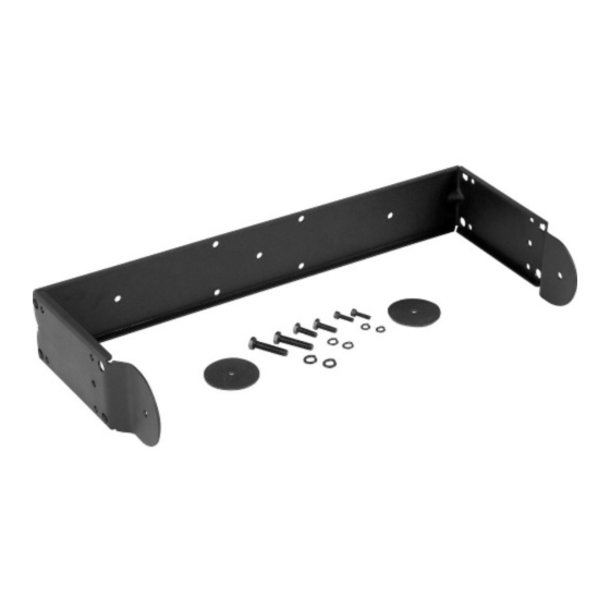
Description
The M
200 installation kit consists of a
b
U-bracket, two M8 x 1.25 hex-head bolts,
four lock washers, two friction pads, and two
3
/
-24 hex-head bolts (see Chart 1). The kit
8
is designed to accommodate the System
TM
200
installation in a variety of ways.
Wall or Ceiling Mounting:
The robust design of the M
b
bracket allows the System 200
to be mounted in almost any position to ob-
tain the desired sound coverage (see Figure
3).
Flying Installations
The M
200 bracket "captures" the speaker
b
CHART 1: M
200 Installation Kit Parts List
b
Item
Description
A
Bracket
B
M8 x 1.25 hex head bolt
C
5/16 split ring lock washer
D
3/8-24 hex head bolt
E
3/8 split ring lock washer
F
Friction washer
in a rigid frame which has structurally sound
locations for attaching rigging hardware.
These attachment points are four 12.7-mm
1
(
/
-in.) diameter holes located on the ends
2
of the bracket. A
lar hardware) can be readily connected to
each attachment point.
System 200
vidually in either a horizontal or vertical po-
sition, or two speakers can be flown together
in a vertical position (see Figures 4 and 5).
200 installation
System 200
TM
speakers
Arrays of two to six speakers are securely
supported in a frame comprised of M
and M
b
array, two M
into the correct alignment position using the
brackets from the M
Quanity
1
2
2
2
2
2
3
/
-in. "quick link" (or simi-
8
TM
speakers can be flown indi-
TM
Horizontal Arrays
300 brackets. To create a horizontal
200 brackets are simply locked
b
300 Horizontal Array
b
Part Number
71914
63310
38144
63311
38834
38829
Mb200
And Mb200W
Installation Kit
• Mounting kit for System
speakers
• May be used in conjuction with
®
OmniMount
1
system
• Versatile design allows the
speaker to be aimed at any angle
from wall or ceiling
• Provides a rigid frame for flying
one or two speakers
• Creates arrays of two to six speak-
ers when used with the M
Horizontal Array Kit
Kit (see Figure 6). The array is extended by
using one additional M
M
300 kit for each additional speaker. To
b
complete the circle for a six speaker array,
one additional M
300 kit is required. Please
b
refer to Chart 2 to select the exact number of
each kit needed, based on desired array size.
(Note: refer to M
300 Horizontal Array Kit
b
engineering data sheet for detailed instruc-
tions on System 200
struction using M
M
300 Horizontal Array Kits.)
b
200
b
CHART 2: Kit Requirements for
System 200
Array Construction
# of Enclosures
in Array:
2
3
4
5
6 (complete circle)
TM
200
Series 100 support
300
b
200 bracket and one
b
TM
horizontal array con-
200 Installation and
b
TM
Horizontal
# of Kits Req'd
M
200
M
300
b
b
2
1
3
2
4
3
5
4
6
6
Advertisement

Related Manuals for Electro-Voice Mb200


Summary of Contents for Electro-Voice Mb200
- Page 1 Mb200 And Mb200W Installation Kit • Mounting kit for System speakers • May be used in conjuction with ® OmniMount Series 100 support system • Versatile design allows the speaker to be aimed at any angle from wall or ceiling •...
- Page 2 Mb200/Mb200W Installation Kit 200 SPECIFICATION GRAPHICS Wall Mounting Instructions FIGURE 1 —Attaching M 200 Bracket CAUTION: Due to the weight of System to System 200 Speaker (exploded view) speakers, it is imperative that the 200 bracket be properly secured to the wall or ceiling.
- Page 3 Mb200/Mb200W Installation Kit FIGURE 4A — Correct and Incorrect Eyebolt FIGURE 4B — Horizontal Suspension of a FIGURE 4C — Horizontal Suspension of a Orientation System 200 Speaker Using System 200 Speaker Using 200 Installation Kit (side view) 200 Installation Kit...
- Page 4 M-F, 8:00 a.m. to 5:00 p.m. Eastern Stan- function resulting from use or operation of Electro-Voice shall not be liable for any inci- dard Time. the product other than as specified in the...
Need help?
Do you have a question about the Mb200 and is the answer not in the manual?
Questions and answers