DeVilbiss AG360 Series Service Manual

DeVilbiss AG360 Series Service Manual

Low pressure, air atomisation automatic spray gun, with lever or screw type manifold
Hide thumbs Also See for AG360 Series:

Advertisement

SERVICE MANUAL
EN
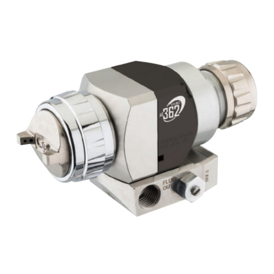
DEVILBISS AG360 Series:
AG362 Low Pressure, Air Atomisation Automatic
Spray Gun, with Lever or Screw Type Manifold.
II
IMPORTANT! DO NOT DESTROY
It is the Customer's responsibility to have all operators and service personnel read and understand this
manual.
Contact your local DeVilbiss representative for additional copies of this manual.
READ ALL INSTRUCTIONS BEFORE OPERATING THIS DEVILBISS PRODUCT.
1/28
SB-E-2-643 R5.0

Advertisement

Table of Contents
loading

Summary of Contents for DeVilbiss AG360 Series

  • Page 1 IMPORTANT! DO NOT DESTROY It is the Customer's responsibility to have all operators and service personnel read and understand this manual. Contact your local DeVilbiss representative for additional copies of this manual. READ ALL INSTRUCTIONS BEFORE OPERATING THIS DEVILBISS PRODUCT. 1/28...
  • Page 2: Manifold Connections

    FUNCTIONAL DESCRIPTION The AG362 low pressure air atomising spray guns are designed to be fast changeover, modular construction applicators, for spray finishing on machines and fixed mountings. The AG362 can be mounted on either a rear entry, lever operated, fast detachable manifold, or a screw attached, low profile manifold, dependant on the part number selected and mounting preference.
  • Page 3: Product Description

    Product Description: AG362 This Product is designed for use with: Solvent and water based materials Suitable for use in hazardous area: Zone 1 & 2 Protection Level: II 2 G X T6 Vibration Level: Sound Pressure Level: Available on request Sound Power Level: Available on request Finishing Brands UK,...
  • Page 4 In this part sheet, the words WARNING, CAUTION and NOTE are used to emphasise important safety information as follows: WARNING CAUTION NOTE Hazards or unsafe practices which could result in Hazards or unsafe practices which could result in Important installation, operation or maintenance severe personal injury, death or substantial minor personal injury, product or property information.
  • Page 5: Fluid Tip

    AG362 GUN PART NUMBER FORMAT & PART SELECTION GUIDE AIR CAP FLUID TIP Conventional Size & construction See table 2 Trans-Tech/Compliant HVLP See table 1 AG362 TE10 085N VALVE OPTIONS GUN HEAD FLUID PASSAGEWAYS Single hole head feed Control Valve Head recirculation Plugged MANIFOLD TYPE...
  • Page 6 TABLE 2 - AG362 RECOMMENDED FLUID TIP / AIR CAP COMBINATIONS AIR CAP Atomisation Type 0.5mm 0.7mm 0.85mm 1.0mm 1.2mm 1.4mm 1.6mm 1.8mm 2.0mm 2.2mm 2.8mm Conventional Conventional Conventional For Conventional tip & needle part numbers, see table 3. TE10 Trans-Tech TE20 Trans-Tech...
  • Page 7 Compressed air take-off Shut-off valve Air filter Air regulator & gauge 3/2 solenoid valve, normally closed Quick exhaust valve & silencer CAP - 1/8" G CYL - 1/8" G WARNING The spray gun must be earthed to dissipate any electrostatic charges which may be created by fluid or air flows.
  • Page 8: Fluid Filter

    TYPICAL FLUID CONNECTION SCHEMATIC - LEVER TYPE MANIFOLD AG362-XXXX-XXXX-L AG362U-XXXX-XXXX-L FRONT VIEW FRONT VIEW Fluid filter Fluid supply Shut-off valve Fluid restrictor valve Fluid reservoir Fluid - 1/8" G NOTE Protective coatings have been used for storage protection. Flush the equipment fluid passageways with appropriate solvent before use.
  • Page 9 TYPICAL AIR CONNECTION SCHEMATIC - SCREW TYPE MANIFOLD Compressed air take-off Shut-off valve Air filter Air regulator & gauge 3/2 solenoid valve, normally closed Quick exhaust valve & silencer CAP - 1/4" G CYL - 1/8" G WARNING The spray gun must be earthed to dissipate any electrostatic charges which may be created by fluid or air flows.
  • Page 10 TYPICAL FLUID CONNECTION SCHEMATIC - SCREW TYPE MANIFOLD AG362-XXXX-XXXX-S AG362U-XXXX-XXXX-S AG362-XXXX-XXXX-T FRONT VIEW FRONT VIEW Fluid filter Fluid supply Shut-off valve Fluid restrictor valve Fluid reservoir Fluid - 1/4" NPS NOTE Protective coatings have been used for storage protection. Flush the equipment fluid passageways with appropriate solvent before use.
  • Page 11 SPRAY GUN AND MANIFOLD INSTALLATION AG362 - LEVER TYPE MANIFOLD AG362 - SCREW TYPE MANIFOLD 11/28 SB-E-2-643 R5.0...
  • Page 12 EXPLODED VIEW PARTS LIST ASSEMBLY REF. PART No. DESCRIPTION QTY. SEE TABLE AIR CAP & RETAINING RING PRO-405-K RETAINING RING SUB ASSEMBLY JGA-156-K5 SPRING CLIP (KIT OF 5) SEE TABLE FLUID TIP SN-69-K SPRAYHEAD & PIN ASSY SN-18-1-K2 GASKET (KIT OF 2) SPA-152-K HEAD SPA-152U-K...
  • Page 13 PARTS LIST ASSEMBLY REF. PART No. DESCRIPTION QTY. SPA-29X-K4 O RING (KIT OF 4) SPA-159-K NEEDLE PACKING SPA-153-K BODY SPA-52 AIR TUBE S-28223X-K4 O RING (KIT OF 4) S-14192-K4 TORX SCREW (KIT OF 4) S-28220X-K2 O RING (KIT OF 2) SPA-60X-K PISTON &...
  • Page 14: Typical Setting

    TYPICAL SETTING 1. The ATOM air valve controls the atomising air pressure, the FAN valve controls the spray pattern size. To increase the pressure, turn anti-clockwise and to reduce the pressure turn clockwise. 2. Fluid flow can be adjusted with the needle adjustment knob, fluid flow is increased when you turn the knob anti-clockwise.
  • Page 15 MAINTENANCE KEY - MAINTENANCE SYMBOLS Order for disassembly Item Number Petroleum Grease/Jelly Thread Sealant Thread Locker DISASSEMBLY TIP & NEEDLE 15/28 SB-E-2-643 R5.0...
  • Page 16 DISASSEMBLY PACKING DISASSEMBLY PISTON 16/28 SB-E-2-643 R5.0...
  • Page 17: General Faults

    TROUBLESHOOTING MECHANICAL PERFORMANCE GENERAL FAULTS CAUSE CORRECTION No air pressure at gun. Check air supply and air line. Will not spray. Fluid needle adjustment knob not Open fluid needle adjustment knob. open enough. Check fluid tip/needle selection chart Incorrect needle fitted to gun. and fit correct item.
  • Page 18: Air Faults

    FLUID FAULTS CAUSE CORRECTION Fluid tip internal seat scored Replace. damaged or worn. Fluid needle external profile Replace. damaged or worn. Contamination on needle or tip mating surfaces preventing good Thoroughy clean. Slow fluid leak from fluid tip and seal. needle seat.
  • Page 19 LEVER TYPE MANIFOLD FAULTS ASSEMBLY FAULTS CAUSE CORRECTION Spray gun does not locate onto Locking cam is not in the unlock Turn locking cam lever to unlock manifold. position. position on manifold. Turn locking cam lever to lock Locking cam has not been tightened. position on manifold.
  • Page 20 CAUSE CORRECTION Soak cap or tip in suitable solvent and thoroughly clean. Replace fluid tip or air cap if necesarry. Replace fluid tip or air cap if necesarry. Soak cap or tip in suitable solvent and thoroughly clean. Dirt or damage on left or right side Replace fluid tip or air cap if of fluid tip exterior.
  • Page 21 Heavy centre pattern. Turn out counter clockwise to Pattern adjustment valve set too low. achieve correct pattern. Reduce fluid flow by turning fluid Too much material. needle adjusting screw clockwise. Reduce fluid pressure. Material too thick. Thin to correct consistency. Atomising air pressure too low.
  • Page 22 Ball end heavy pattern. Change fluid tip for smaller size or Too much fluid flow. change air cap for different specification air cap. Too much atomisation air pressure. Reduce air pressure. Excessive bounce-back. Check distance (normally 150- Gun too far from surface. 200mm).
  • Page 23 MOUNTING ADAPTOR OPTIONS - SCREW TYPE MANIFOLD SPA-173-K SPA-174-K Horizontal mounting bar and screws Vertical mounting bar and screws SPA-175-K SPA-176-K Mounting block and screws Index adjustment and screws 23/28 SB-E-2-643 R5.0...
  • Page 24 ACCESSORIES DESCRIPTION PART No. SPA-417-K Micrometer needle adjustment assembly. SPA-167-K Fiixed needle position end cap. SPA-426-K Ratchet needle adjustment assembly. SPA-414-K Control Valve Atomisation & fan blanking plugs, replaces items (34) see exploded SPA-111-K2 view. Atomisation & fan low profile control valve, replaces item (34) see SPA-423-K exploded view.
  • Page 25 DIMENSIONS AG362- LEVER TYPE MANIFOLD AG362- SCREW TYPE MANIFOLD 25/28 SB-E-2-643 R5.0...
  • Page 26 NOTES 26/28 SB-E-2-643 R5.0...
  • Page 27 NOTES 27/28 SB-E-2-643 R5.0...
  • Page 28 © 2015 Carlisle Fluid Technologies,Inc., dba Finishing Brands. All rights reserved. DeVilbiss is part of Finishing Brands, a global leader in innovative spray finishing technologies. For technical assistance or to locate an authorised distributor, contact one of our international sales and customer support locations below.

This manual is also suitable for:

Ag362

Table of Contents