Table of Contents
Advertisement
Quick Links
4025650/7
Installation and Maintenance Instructions
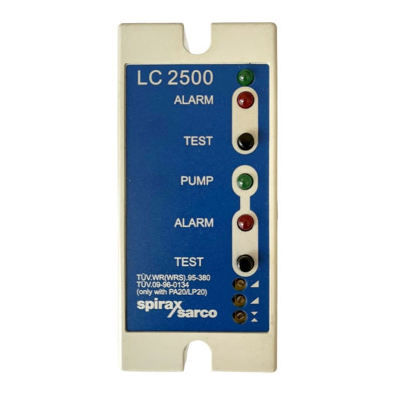
LC2500
ALARM
TEST
PUMP
ALARM
TEST
Printed in the UK
IM-P402-50 AB Issue 7
LC2500
Level Controller
1. General
safety information
2. General
product information
3. Installation
4. Setting up the controller
5. Wiring diagrams
6. Commissioning
7. Maintenance
8. Fault finding
IM-P402-50
AB Issue 7
© Copyright 2002
1
Advertisement
Table of Contents

Summary of Contents for Spirax Sarco LC2500
- Page 1 4025650/7 IM-P402-50 AB Issue 7 LC2500 Level Controller Installation and Maintenance Instructions 1. General safety information LC2500 2. General product information ALARM 3. Installation TEST 4. Setting up the controller PUMP ALARM 5. Wiring diagrams TEST 6. Commissioning 7. Maintenance 8.
-
Page 2: General Safety Information
1. General safety information Your attention is drawn to Safety Information Sheet IM-GCM-10 as well as to any National or local regulations. Safe operation of the product depends on it being properly installed, commissioned and maintained by a qualified person in compliance with the operating instructions. It is essential to comply with general installation and safety instructions for pipeline and plant construction, as well as to make proper use of tools and safety equipment. -
Page 3: General Product Information
2. General product information The LC2500 is a two channel level controller with adjustable switching levels, and is normally used in conjunction with a capacitance type level probe. Either of the channels, (designated A and B), can be set to provide a high or low alarm, and channel B can also provide an adjustable pump on /off control. -
Page 4: Installation
Rocking the controller in the vertical plane will ease removal. The controller must be installed in a suitable industrial control panel or fireproof enclosure to provide environmental protection (pollution degree 2). Spirax Sarco can provide suitable plastic or metal enclosures (for standard controller only). -
Page 5: Setting Up The Controller
Relay rating table: Version Relay load type Rating Resistive at 250 Vac Standard Inductive at 250 Vac Lamp or resistive at 240 Vac Tungsten filament at 240 Vac UL Listed ac motor at 240 Vac ¼ HP (2.9 A) ac motor at 120 Vac HP (3 A) Pilot duty (control circuits / coils) C300 (2.5 A) -
Page 6: Wiring Diagrams
Channel B pump control Channel B alarm Channel B pump control Fig. 3 The LC2500 is supplied with the switch setting set as shown in bold 5. Wiring diagrams 5.1 Screen connection An earth current loop is created if a wire or screen is connected between two earth points, which are at different potential (voltage). - Page 7 5.3 Pumping in or out and low alarm LC2500 controller Pumping in or out and high alarm Fuse 3 A max. Mains supply Fuse 3 A max. Low / high alarm relay Normal Circuit broken at alarm Channel Alarm lamp or bell...
- Page 8 High alarm /low alarm LC2500 controller Two low alarms Two high alarms Fuse 3 A max. Mains supply Fuse 3 A max. Channel Normal Circuit broken at alarm A relay Alarm lamp or bell Alarm Fuse 3 A max. Channel...
- Page 9 5.5 Wiring diagram UL version PA20 preamplifier and LP20 capacitance probe (see PA20 and LP20 Installation and Maintenance Instructions) LC2500 controller Termination Screen Brown 11 IN 1 Orange Common Black See PA20 Installation and Maintenance Instructions Flying leads for sensitivity selection supplied with PA20 approximately 300 mm (12")
- Page 10 5.7 Multiple controllers Several controllers can be connected to a single probe or 4 -20 mA source if required, for example to provide multiple alarm signals. Connect wiring and set switches 1 and 2 as shown in Fig.16. Additional unit Switch positions for capacitance probe.
- Page 11 6. Commissioning Note: Control and alarm levels are set by adjusting the potentiometers on the front panel. Channel A is used for an alarm only. Channel B may be used either as an additional alarm, or for pump on-off control. It is not possible to set Channel B as an alarm if pump control is also required.
-
Page 12: Maintenance
Literature is obtainable from Spirax Sarco which gives general information on boiler water level variations. If the out of range alarm is set to ON (Switch 6), the low limit alarm may be tested by disconnecting the probe plug.


Need help?
Do you have a question about the LC2500 and is the answer not in the manual?
Questions and answers