
Related Manuals for MKN Combisteamer TKECOD610T


Summary of Contents for MKN Combisteamer TKECOD610T
- Page 1 Read the operating instructions prior to commissioning Installation instructions Combisteamer Unit Type of energy Unit type Model SpaceCombi Magic Electric Floor-standing unit TKECOD610T Team 4127002--0AIBE-C en-GB...
- Page 2 Fax +49 5331 89-280 Internet www.mkn.com Copyright All rights to text, graphics and pictures in this documentation are held by MKN Maschinenfabrik Kurt Neubauer GmbH & Co. KG. Distribution or duplication is only permitted with the prior written consent of MKN.
-
Page 3: Table Of Contents
Directory of contents 1 Introduction ................. 5 1.1 About this manual ................ 5 1.1.1 Explanation of signs .................. 6 1.2 Staff qualification ................ 7 1.3 Use of the unit ................... 7 1.4 Warranty .................... 7 2 Safety information .............. 8 3 Description of the unit ............. 10 3.1 Overview of the unit ............... 10 3.2 Equipment and connection data ... - Page 4 Directory of contents 7.2 Checking the controls .............. 38 7.3 Checking the monitoring of the cooking zone door .... 39 7.4 Heating the unit up and rinsing it out ........... 39 8 Putting the unit into service .......... 40 8.1 Nameplate .................. 40 8.2 Filling out the commissioning report ........... 41 Installation instructions...
-
Page 5: 1 Introduction
Introduction 1 Introduction 1.1 About this manual The instruction manual is part of the unit and contains information on safe installation of the unit. Observe and adhere to the following instructions: • Read the instruction manual in its entirety prior to installation. •... -
Page 6: Explanation Of Signs
Introduction 1.1.1 Explanation of signs DANGER Imminent threat of danger Failure to comply will lead to death or very severe injuries. WARNING Possible threat of danger Failure to comply can lead to death or very severe injuries. CAUTION Dangerous situation Failure to comply can lead to slight or moderately severe injuries. -
Page 7: Staff Qualification
Introduction 1.2 Staff qualification Explanation of qualification Skilled staff • Skilled staff are those, who due to their profes- sional training, knowledge and experience as well as their knowledge of the relevant standards can assess the tasks given to them and recognize any possible dangers. -
Page 8: 2 Safety Information
Safety information 2 Safety information The unit complies with applicable safety standards. Residual risks associated with operation or risks resulting from incorrect operation cannot be ruled out and are mentioned specifically in the safety instructions and warnings. The installer must be familiar with regional regulations and observe them. - Page 9 Safety information Setup Risk of property damage and personal injury from improper setup • Ensure that the installation area has adequate load-bearing capacity. • Wear safety shoes and protective gloves. Electrical connection Risk of fire from improper connection • Observe applicable regional regulations of the electrical utility. •...
-
Page 10: 3 Description Of The Unit
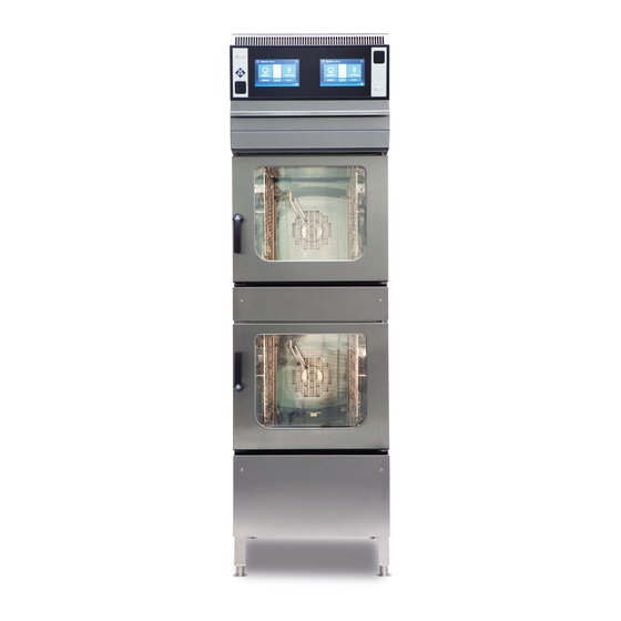
Description of the unit 3 Description of the unit 3.1 Overview of the unit Image: Floor-standing unit a Air outlet j Equipment leg b Control unit k Nameplate c Filter drawer l Discharge channel for bottom unit d Condensate baffle m Cooking zone in bottom unit e Support rack n Discharge channel for top unit... -
Page 11: Equipment And Connection Data
Description of the unit 3.2 Equipment and connection data Size Dimensions Unit 550 x 880 x 1908 Length x Width x Height (mm) Due to construction minimum distance between unit and wall (mm) Weight Unit ≈ (kg) Emissions Sound level (db(A)) <... - Page 12 Description of the unit Size Connected load (kW) 19.6 Fuse (A) Voltage (V) Connected load (kW) 14.8 Fuse (A) Voltage (V) Connected load (kW) 15.6 Fuse (A) Voltage (V) Connected load (kW) 16.2 Fuse (A) Voltage (V) Connected load (kW) 15.8 Fuse (A) Type of connection...
- Page 13 Description of the unit Size Iron FE (mg/l) < 0.2 Connection pressure (kPa (bar)) 200 (2) — 600 (6) Connection (") R 3/4 male thread Tap water connection Water type Tap water, cold Carbonate hardness CaCO < 4 (22,2) (mmol/l (°dH)) Connection pressure (kPa (bar)) 200 (2) —...
- Page 14 Description of the unit Basic control setting Basic setting Parameter Standard Adjustment Explanation value range Actual voltage 100 — 500 V Set the local, mean voltage between the line conductors. Date/time yyyy - mm - dd Year - Month - Day hh : mm Hour : Minute Altitude...
- Page 15 Description of the unit Basic control setting (Advanced) Basic setting Parameter Standard Adjustment Explanation value range Generator operation 0 = No If a generator is used to supply electricity 1 = Yes Vapour elimination 0 = Low Sets the vapour elimination level 1 = Normal 2 = High Time format...
-
Page 16: 4 Transporting The Unit
Transporting the unit 4 Transporting the unit CAUTION Risk of property damage and personnel injury from tipping equipment • Do not linger next to or behind raised equipment. • Move raised equipment carefully. ATTENTION Risk of physical damage from improper transport •... -
Page 17: Unpacking The Unit
Transporting the unit 4.2 Unpacking the unit CAUTION Risk of injury from sharp edges • Wear protective gloves. When unpacking the unit, inspect it for transport damage. Do not install damaged units or put into service. 1. Remove the packaging. 2. -
Page 18: 5 Setting Up The Unit
Setting up the unit 5 Setting up the unit CAUTION Risk of crushing from improper setup • Protect the unit and work area during setup and alignment. CAUTION Risk of fire from failure to observe applicable regional fire prevention regulations •... -
Page 19: Minimum Clearances
Setting up the unit 5.1 Minimum clearances Image: Minimum clearances to walls, ceiling or units All dimensions in mm * Depending on the kitchen ventilation system and the material composition of the ceiling The following clearances from walls, ceilings or other equipment must be maintained when installing the unit: •... -
Page 20: Placing The Unit On The Equipment Legs
Setting up the unit 5.3 Placing the unit on the equipment legs Requirement The floor must support the weight of the unit 1. Use appropriate lifting gear to lift the unit. 2. Set up the unit in accordance with the planning drawing. 3. -
Page 21: Checking The Filter On The Air Recirculation Hood
Setting up the unit 5.5 Checking the filter on the air recirculation hood Image: Filter for air recirculation hood a Condensation baffle e Vapour inlet b Filter drawer f Filter pad, yellow c Air outlet g Air filter d Air recirculation hood h Active carbon filter Requirements Unit not live Step ladder set up securely... -
Page 22: Fastening The Unit To The Floor
Setting up the unit 5.6 Fastening the unit to the floor 5.6.1 Securing the unit against tilting WARNING Risk of accidents from inadequate fastening The unit may tip over • The unit must be fastened to the floor by suitable methods depending on the type of unit. - Page 23 Setting up the unit Floor without steam barrier In the case of floors without a steam barrier, the floor plates are screwed to the floor with the enclosed screws. Image: A: Position of the floor plate; B: Floor plate screwed to the floor a Cap nut d Floor plate b Holding plate...
- Page 24 Setting up the unit Floor with steam barrier In the case of floors with a steam barrier, the floor plates are not screwed to the floor but glued with the enclosed adhesive. Image: A: Position of the floor plate; B: Floor plate glued to the floor a Cap nut d Floor plate b Holding plate...
-
Page 25: 6 Connecting The Unit
Connecting the unit 6 Connecting the unit DANGER Risk of personal injury and physical damage from electric shock • Prior to working on the unit, ensure that the unit has been disconnected from the mains. • Do not operate the unit with the housing open. CAUTION Risk of injury from sharp edges •... -
Page 26: Making The Electrical Connection
Connecting the unit Attaching the rear panel ATTENTION Risk of physical damage from leaky housing • Check seals when attaching the housing parts. • Replace damaged gaskets. 1. Carefully press in the rear panel. 2. Screw in the screws on the rear panel. The rear panel must be in contact with the unit on all sides. - Page 27 Connecting the unit Permanent connection CAUTION Risk of property damage and personal injury from improper installation • In the case of a permanent electrical connection, install an all-phase disconnect switch before the unit. Install an all-phase disconnect switch if the unit will be connected permanently to the electric mains.
-
Page 28: Connecting The Power Connection Cable
Connecting the unit Potential equalisation Image: Symbol for potential equalisation The unit can be included in a potential equalisation system by means of appropriately sized wiring. 6.2.1 Connecting the power connection cable DANGER Risk of personal injury and physical damage from electric shock •... -
Page 29: Connecting The Power Optimizing System
Connecting the unit 3. Secure the power connection cable with cable ties. 4. Tighten the cable gland securely to provide strain relief. 5. Close the housing (see "Opening and closing the housing"). 6. Fill out the Commissioning report. 6.2.2 Connecting the power optimizing system DANGER Risk of personal injury and physical damage from electric shock... -
Page 30: Connecting To The Potential Equalisation Circuit
Connecting the unit Requirement Unit not live Power connection cable not live Housing opened 1. Pull the power connection cable into the unit through the cable gland. 2. Bring the power connection cable to the connection terminals. 3. Connect the power connection cable in accordance with the wiring diagram. -
Page 31: Connecting The Kitchen Management System
Connecting the unit 6.3 Connecting the kitchen management system The units can be connected with a RJ45 plug to a kitchen management system. DANGER Risk of personal injury and physical damage from electric shock • Prior to working on the unit, ensure that the unit has been disconnected from the mains. -
Page 32: Making The Basic Control Setting
Connecting the unit 6.4 Making the basic control setting Image: Main menu a Stand-by button e Language selection button b Information bar f "Equipment functions" button c FlexiHelp button g "autoChef" button d "myCooking" button 6.4.1 Changing the basic control setting By entering the password "2100", the basic settings for the installation can be displayed and changed. -
Page 33: Making The Water Connection
Connecting the unit 6.5 Making the water connection Installation work with tap water Installation work on tap water lines and the unit may only be performed by a specialist company, which is approved by the water utility company in the particular region. The applicable regional regulations, standards and guidelines must be observed, as well as the connection conditions imposed by the water utility company responsible. -
Page 34: Connecting The Tap Water Connection Line
Connecting the unit 6.5.1 Connecting the tap water connection line Image: Water connection a Softened tap water d Tap water connection b Connection line e Backflow preventer c Soft water connection f Tap water Requirement Water pressure complies with the specified range (see "Equipment and connection data") Backflow preventer installed The connection lines are pressure-tight and suitable for tap water... -
Page 35: Connecting Softened Tap Water To Both Connections
Connecting the unit 6.5.2 Connecting softened tap water to both connections Image: Connecting softened tap water to both connections a Backflow preventer d T-piece b Connection line e Seal c Dirt filter f Softened tap water If only softened tap water is available at the installation site, use a T- piece to connect both water connections on the unit to each other. -
Page 36: Connecting The Wastewater Line To A Permanent Connection
Connecting the unit Professional qualification for wastewater specialist Installation work on wastewater lines and the unit may only be carried out by a wastewater specialist from the specialist company assigned to the work. 6.6.1 Connecting the wastewater line to a permanent connection Image: Wastewater line with vacuum breaker to a permanent connection a Sewer system d Pipe clamp... -
Page 37: Connecting Wastewater Line To Collection Basin (Optional)
Connecting the unit 6.6.2 Connecting wastewater line to collection basin (optional) Image: A: Collection basin; B: Wastewater connection a Wastewater line f Fastening screw (fitted to building) b Locknut g Wastewater line (in building) c Adjustable foot h Wastewater connection d Waste trap i Sewer system e Collection basin... -
Page 38: 7 Checking Operation
Checking operation 7 Checking operation DANGER Risk of personal injury and physical damage from unsuccessful operational check • Do not put the unit into service. • Contact customer service. Requirement Power connection made Water connection made Wastewater connection made Unit cleaned 7.1 Checking the air recirculation hood Requirements Cooking zone door closed 1. -
Page 39: Checking The Monitoring Of The Cooking Zone Door
Checking operation 7.3 Checking the monitoring of the cooking zone door 1. Switch on the unit and start any cooking program (see operating instructions). The unit starts to heat. The fan wheel is turning. 2. Open the cooking zone door during operation. The unit shuts off the heating function. -
Page 40: 8 Putting The Unit Into Service
Function successfully tested Housing closed 1. Instruct operator. 2. Fill out the Commissioning report. 8.1 Nameplate c d e MKN Maschinenfabrik Kurt Neubauer GmbH & Co. KG, Halberstädter Str. 2a, D-38300 Wolfenbüttel Typ: Item-Nr.: Bez.: www.mkn.com Image: Nameplate information... -
Page 41: Filling Out The Commissioning Report
Putting the unit into service 8.2 Filling out the commissioning report General information Information from the nameplate entered? Type: Desig.: Item no.: (if present) Obvious damage to the unit? What and where?: Unit levelled? General information Unit fastened to the floor? Secured against tilting Secured against sliding Floor screw fitting... - Page 42 Putting the unit into service Basic control setting 80 % power set? 100 % 80 % Current voltage set? Voltage: Audible signal volume set? Quiet Loud Signal tone selected? Volume unit set? fl.oz. (Imperial) fl.oz. (U.S.) Power optimisation system set? Water filter maintenance set? No maintenance message Maintenance message at:...
- Page 43 Putting the unit into service Air recirculation hood Checked that the filter is located firmly and correctly? Function check Controls are functioning? Do both fan speeds function for the air recirculation hood? Monitoring of the cooking zone door is functioning? Unit heated up and rinsed out? Final notes Was the unit put into service?
- Page 44 Putting the unit into service Operator training was provided by: Signature Company Installer City, date Installation instructions...
- Page 48 www.mkn.com...
Need help?
Do you have a question about the Combisteamer TKECOD610T and is the answer not in the manual?
Questions and answers