Sign In
Upload
Manuals
Brands
THORLABS Manuals
Temperature Controller
Blueline Series
THORLABS Blueline Series Manuals
Manuals and User Guides for THORLABS Blueline Series. We have
5
THORLABS Blueline Series manuals available for free PDF download: Operation Manual, Operating Manual
THORLABS Blueline Series Operation Manual (119 pages)
Optical sources
Brand:
THORLABS
| Category:
Measuring Instruments
| Size: 0 MB
Table of Contents
Table of Contents
3
1 General Description of the Optical Source Modules
7
Safety
7
Warranty
11
Properties
12
Protections for the Laser Diode
12
Features
14
Technical Data
15
Common Technical Data for the WDM Modules
15
Common Technical Data for the Ls8Xxxx Modules
16
Common Technical Data for the CWDM Modules
17
2 Operating the PRO8000 (-4) / PRO800 Optical Source Modules
18
Operating Elements on Front Panel
18
Connecting External Components
19
Connecting an Optical Fiber
19
Connecting an External RF Modulation Source
19
Connecting an External DC Modulation Source
19
Modulating the Optical Source Modules
20
Direct Modulation Via an Internal Bias-T
21
Direct Modulation Via Internal DC Bias-T
24
External Modulation (PM-Output Recommended)
28
Coherence Control
29
Operating the WDM and CWDM Modules
30
Functions in the Main Menu
30
Error Messages
33
Functions in the Channel Menu (CW Modules)
35
Functions in the Channel Menu (Modules with Direct Modulation)
40
Functions in the Channel Menu (Wdmias-T-DC or RF)
46
Operating the LS Modules
52
Functions in the Main Menu
52
Error Messages
55
Functions in the Channel Menu (LS)
57
3 Communication with a Control Computer
60
General Notes on Remote Control
60
Nomenclature
61
Data Format
61
Commands of the Different Light Source Modules
63
Select the Module Slot
63
WDM Modules with CW Mode
64
CWDM Modules
72
WDM Modules with Direct Modulation Mode
78
WDM Modules with Bias-T
88
LS Modules
95
Status Reporting
99
Standard Event Status Register (ESR)
101
Standard Event Status Enable Register (ESE)
101
Status Byte Register (STB)
102
Service Request Enable Register (SRE)
102
Reading the STB by Detecting SRQ
103
Reading the STB by *STB? Command
103
Reading the STB by Serial Poll
103
Device Error Condition Register (DEC)
104
Device Error Event Register (DEE)
104
Device Error Event Enable Register (EDE)
105
Error Messages
106
4 Service and Maintenance
108
Recalibration of Laser Wavelength
108
Shutter Function Control
108
Troubleshooting
109
5 Appendix
111
Thorlabs "End of Life" Policy (WEEE)
111
Waste Treatment on Your Own Responsibility
111
Ecological Background
112
List of Acronyms and Abbreviations
113
List of Figures
115
Certifications and Compliances
116
Addresses
118
Advertisement
THORLABS
Blueline Series
Operation Manual
THORLABS Blueline Series Operation Manual (87 pages)
Mainframe
Brand:
THORLABS
| Category:
Laboratory Equipment
| Size: 0 MB
Table of Contents
Table of Contents
4
Figure 2 Operating Elements on Rear Panel
4
1 General Remarks
8
Safety
9
Warranty
13
Technical Data
14
2 Operating the PRO8000 (-4) / PRO800 Mainframe
16
Operating Elements on Front Panel
16
Figure 1 Front Panel View of the PRO8000
16
Menus of the PRO8000 (-4) / PRO800
20
After Power on
20
Main Menu
21
The Cursor
21
Selecting a Module
22
Setup Menu
22
3 Communication with a PC
24
Hardware Standard RS 232-C
24
Figure 3 RS232C Connection Cable
25
Emulating the IEEE488 Bus Commands
26
Interface Specification
26
Operating Commands
27
Service Request Emulation
27
Hardware Standard IEEE 488.1
28
IEEE 488.1 Subsets of the PRO8000 (-4) / PRO800
28
Device Address and String Terminator
29
Starting the IEEE488 Interface
30
IEEE488 Bus Commands
31
Software Standard IEEE 488.2
33
Nomenclature
33
Program and Response Messages
33
Data Format
34
Common Commands and Queries
36
Module Specific Commands and Queries
40
Error Messages
40
Error Queue Empty
41
100
41
200
42
300
42
400
43
Status Reporting
44
Standard Event Status Register (ESR)
44
Figure 4 the 7 Registers ESR, ESE, STB, SRE, BFC, BFR and BFE
46
Figure 5 the Registers DESR, DESE, DEC,DEE and EDE
47
Standard Event Status Enable Register (ESE)
48
Status Byte Register (STB)
48
Service Request Enable Register (SRE)
49
Device Error Summary Register (DESR)
49
Device Error Summary Enable Register (DESE)
49
Device Error Condition Register (DEC)
50
Device Error Event Register (DEE)
50
Device Error Event Enable Register (EDE)
50
Block Function Condition Register (BFC)
51
Block Function Event Register (BFR)
51
Block Function Enable Register (BFE)
51
Service Request by Detecting SRQ
51
Service Request by *STB? Command
51
Hints for Setting up Control Programs
52
System Reset
53
Power on Reset
53
Reset by Device Clear
54
Reset by the Clear Status Command
54
Reset by the Reset Command
54
Reset by Interface Clear
54
The PRO8000 (-4) / PRO800 "ELCH" - Macro Functions
55
What Is ELCH
55
Basic Settings
55
Individual Settings for a Measurement
55
Cascading Several ELCH Runs
57
Figure 6 ELCH Memory Overflow
59
Which Values Do You Want to Measure
60
Setting the Desired Measurement Mode
60
Reading the 'ELCH' Status
62
Reading the Measured Values
62
Example of an ELCH Measurement Procedure
65
Possible ELCH Error Sources
67
4 Maintenance and Repair
69
General Care
69
Cleaning
69
Line Voltage
69
Exchanging the Mains Fuse
69
Figure 7 Changing the Mains Fuse
70
Repair
71
Installing and Uninstalling Modules
71
Troubleshooting
73
Updating the PRO8000 (-4) / PRO800 Firmware
76
Update Procedure
77
5 Service
78
Line Voltage Setting
78
Figure 8 Setting the Mains Voltage
79
Internal Fuse Replacement
80
Figure 9 Internal Fuses
80
6 Listings
81
List of Acronyms
81
List of Figures
82
Certifications and Compliances
83
Addresses
86
THORLABS
Blueline Series
Operating Manual
THORLABS Blueline Series Operating Manual (80 pages)
Brand:
THORLABS
| Category:
Measuring Instruments
| Size: 0 MB
Table of Contents
Table of Contents
4
1 General Description of the Current Module Ldc8Xxx
8
Safety
8
Warranty
10
Features
11
Safety Measures for the Laser Diode
11
General Functions
13
Technical Data
14
Common Data Ldc8Xxx
14
Individual Technical Data
15
Operating Elements at the Front Panel of the Module
21
Pre-Settings
22
Setting Limit Values
22
Connecting Components
25
Pin Assignment LDC8001 to LDC8040
25
Pin Assignment Ldc8Xxx with True Bipolar Option
26
Pin Assignment LDC8080
28
Connecting Laser- and Monitor Diodes
30
Connecting Interlock and Status Display
33
Using the Modulation Input
35
2 Operating the Ldc8Xxx
36
Functions in the Main Menu
36
Display
36
Selecting a Module
37
Setting the Main Parameter
37
Functions in the Channel Menu
38
Display
38
Changing Parameters
39
Selecting the Polarity of the Laser and the Monitor Diode
40
Calibrating the Monitor Diode
40
Selecting Constant Current or Constant Power Mode
41
Selecting a TEC Module for Temperature Protection
42
Activating the Temperature Protection
42
Bias Voltage for the Monitor Diode
43
Switching on and off
44
Error Messages
45
3 Communication with a Control Computer
47
General Notes on Remote Control
47
Nomenclature
48
Data Format
48
Commands
50
Select the Module Slot
50
Calibrating a Photo Diode (CALPD)
50
Programming the Laser Diode Current (ILD)
51
Programming the Monitor Diode Current (IMD)
53
Switching the Output on and off (OUTP)
55
Selecting the Laser Diode Polarity (LDPOL)
55
Programming the Laser Diode Software-Limit (LIMC)
56
Reading the Laser Diode Hardware-Limit (LIMCP)
56
Programming the Monitor Diode Current Limit (LIMM)
57
Programming the Optical Power Limit (LIMP)
58
Selecting the Mode of Operation (MODE)
58
Switching the Bias Voltage on and off (PDBIA)
59
Selecting the Photo Diode Polarity (PDPOL)
59
Programming the Optical Power (POPT)
60
Switching the Temperature Protection on and off (TP)
60
Selecting a TEC Module for Temperature Protection (TPSLOT)
61
Querying the Module Type
61
Reading the Laser Diode Voltage (VLD)
62
1000
63
Status Reporting
65
Standard Event Status Register (ESR)
67
Standard Event Status Enable Register (ESE)
67
Status Byte Register (STB)
68
Service Request Enable Register (SRE)
68
Reading the STB by Detecting SRQ
69
Reading the STB by "*STB?" Command
69
Reading the STB by Serial Poll
69
Device Error Condition Register (DEC)
70
Device Error Event Register (DEE)
70
Device Error Event Enable Register (EDE)
71
4 Service and Maintenance
72
General Remarks
72
Troubleshooting
73
5 Listings
76
List of Acronyms and Abbreviations
76
List of Figures
77
Advertisement
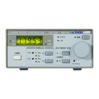
THORLABS Blueline Series Operation Manual (51 pages)
Laser Diode Controller
Brand:
THORLABS
| Category:
Controller
| Size: 1 MB
Table of Contents
Table of Contents
3
1 General Information
7
At a Glance
7
Safety
9
Ordering Codes and Accessories
11
2 Getting Started
12
Unpacking
12
Preparation
12
Operating Elements
13
Operating Elements on Front Panel
13
Operating Elements on Rear Panel
14
First Operation
15
3 Operating the Ldc2Xx
16
Connecting Components
16
9-Pole SUB-D Output Jack
16
Interlock and Control LED for LASER on
17
Connecting the Laser Diode and Photodiode
18
Analog Control Output for the Laser Current
20
Setting the Current Limit "ILIM
21
Selecting the Laser Diode Polarity
21
Constant Current Mode (CONST I)
23
Constant Power Mode (CONST P)
24
Changing the "IPD" Setting Range
26
Calibrating the Optical Power Display
27
Analog Modulation of the Laser Diode
27
Over-Temperature-Protection of the Ldc2Xx
28
4 Remote Control
29
5 Maintenance and Repair
30
Maintenance
30
Line Voltage Setting
31
Replacing the Mains Fuse
32
Internal Fuse Replacement
33
Troubleshooting
34
6 Appendix
36
Warranty
36
Certifications and Compliances
37
Technical Data
39
Common Data
39
Individual Data LDC200V
40
Individual Data LDC201U
41
Individual Data LDC202B
42
Individual Data LDC205B
43
Individual Data LDC210B
44
Individual Data LDC220
45
Thorlabs "End of Life" Policy (WEEE)
46
Waste Treatment on Your Own Responsibility
46
Ecological Background
47
List of Acronyms
48
List of Figures
48
Addresses
49
THORLABS Blueline Series Operation Manual (49 pages)
Thermoelectric Temperature Controller
Brand:
THORLABS
| Category:
Temperature Controller
| Size: 0 MB
Table of Contents
Table of Contents
3
1 General Information
7
At a Glance
7
General Remarks
7
Protections for the TEC Element
9
Safety
10
Ordering Codes and Accessories
12
2 Getting Started
13
Unpacking
13
Preparation
13
Preparation
14
Operating Elements on Front Panel
14
Operating Elements on Rear Panel
15
Starting up
16
3 Operating the TED200
17
Connecting Components
17
Connecting the TEC Element
18
Control LED for TEC on Mode
19
Connecting a Temperature Sensor
19
Operating the Temperature Controller
23
Setting the TEC Current Limit "ILIM
24
Adjusting the Temperature Control Loop
25
Analog Tuning of the Temperature
27
Analog Temperature Control Output
28
Over-Temperature-Protection of the TED200
28
4 Maintenance and Repair
29
Maintenance
29
Line Voltage Setting
30
Replacing the Mains Fuse
32
Internal Fuse Replacement
33
Calibrating the Temperature Sensor
34
Switching off the I-Share of the Temperature Control Loop
35
Troubleshooting
37
5 Appendix
39
Warranty
39
Certifications and Compliances
40
Technical Data
42
Thorlabs "End of Life" Policy (WEEE)
44
Advertisement
Related Products
THORLABS Blueline PRO8000
THORLABS Blueline PRO8000-4
THORLABS Blueline PRO800
THORLABS BLINK
THORLABS BLINK-Y1
THORLABS BLINK-Y3
THORLABS BNT001/IR
THORLABS BC106-UV
THORLABS BC207VIS/M
THORLABS BP209-VIS
THORLABS Categories
Measuring Instruments
Controller
Laboratory Equipment
Security Sensors
Industrial Equipment
More THORLABS Manuals
Login
Sign In
OR
Sign in with Facebook
Sign in with Google
Upload manual
Upload from disk
Upload from URL