THORLABS Blueline Series Operation Manual
Optical sources
Hide thumbs
Also See for Blueline Series:
- Operation manual (87 pages) ,
- Operating manual (80 pages) ,
- Operation manual (49 pages)

Related Manuals for THORLABS Blueline Series


Summary of Contents for THORLABS Blueline Series
- Page 1 Operation Manual Thorlabs Blueline™ Series PRO8000 (-4) / PRO800 Optical sources WDM8xxx C81xxxx LS8xxxx 2006...
- Page 2 Version: 2.22 Date: 20.06.2006 © Copyright 2004-2006, Thorlabs GmbH...
-
Page 3: Table Of Contents
Contents Page General description of the optical source modules 1.1 Safety 1.2 Warranty 1.3 Properties 1.3.1 Protections for the laser diode 1.3.2 Features 1.4 Technical data 1.4.1 Common technical data for the WDM modules 1.4.2 Common technical data for the LS8xxxx modules 1.4.3 Common technical data for the CWDM modules Operating the PRO8000 (-4) / PRO800 optical source modules... - Page 4 3.4 Error messages Service and Maintenance 4.1 Recalibration of laser wavelength 4.2 Shutter function control 4.3 Troubleshooting Appendix 5.1 Thorlabs “End of Life” policy (WEEE) 5.1.1 Waste treatment on your own responsibility 5.1.2 Ecological background 5.2 List of acronyms and abbreviations 5.3 List of figures...
- Page 5 In the displays shown by the PRO8 you may find the name PROFILE. PROFILE was the name of the manufacturer before it was acquired by Thorlabs and renamed to Thorlabs GmbH. Thorlabs GmbH This part of the instruction manual contains all the specific information on how to operate the optical source modules WDM8xxxx, C81xxxx and LS8xxxx.
-
Page 7: General Description Of The Optical Source Modules
1.1 Safety 1 General description of the optical source modules 1.1 Safety Attention INVISIBLE LASER RADIATION DO NOT VIEW DIRECTLY WITH OPTICAL INSTRUMENTS! CLASS 1M LASER PRODUCT The modules ‘WDM8xxxx’ are class 1M laser sources. Emitted wavelength: 1 single wavelength in the range 1454 nm … 1625 nm, according to ordered wavelength. - Page 8 1.1 Safety Attention The laser modules supplied by Thorlabs are class 1M laser systems. However, if you collimate or focus the laser beam you will create a class 3R or class 3B laser system! In that case additional safety measures have to be observed!
- Page 9 PRO8000, PRO8000-4 or PRO800. All modules must only be operated with duly shielded connection cables. Only with written consent from Thorlabs may changes to single components be carried out or components not supplied by Thorlabs be used. This precision device is only dispatchable if duly packed into the complete original packaging including the plastic form parts.
- Page 10 1.1 Safety Attention Mobile telephones, cellular phones or other radio transmitters are not to be used within the range of three meters of this unit since the electromagnetic field intensity may then exceed the maximum allowed disturbance values according to EN 50 082-1. The PRO8000 (-4) / PRO800 must not be operated in explosion endangered environments.
-
Page 11: Warranty
1.2 Warranty 1.2 Warranty Thorlabs GmbH warrants material and production of the WDM8xxxx, C81xxxx and LS8xxxx modules for a period of 24 months starting with the date of shipment. During this warranty period Thorlabs GmbH will see to defaults by repair or by exchange if these are entitled to warranty. -
Page 12: Properties
1.3 Properties Properties 1.3.1 Protections for the laser diode To protect the optical sources in the WDM8xxxx, C81xxxx and LS8xxxx modules the PRO8000 (-4) / PRO800 are equipped with the following protection circuits: • Fixed current limit A fixed limit set in factory protects the laser diode against operating errors. •... - Page 13 • LabVIEW ® ® -and LabWindows/CVI drivers ® For the PRO8000 (-4) / PRO800 Thorlabs supplies LabVIEW and LabWin- ®- dows/CVI drivers for MS Windows 32. Please refer to our homepage for the latest driver updates. http://www.thorlabs.com PRO8000 (-4)/800 optical sources / page 7...
-
Page 14: Features
1.3 Properties 1.3.2 Features The laser fibers are connected via FC/APC connectors at the front of the module. (Other connectors optional). Each module is protected against overheating of the output stage by an automatic shutdown. The LED "ERR" indicates that the module is switched off. After a decline in temperature of about 10 °C the LED "ERR"... -
Page 15: Technical Data
1.4 Technical data 1.4 Technical data (All technical data are valid at 23 ± 5°C and 45 ±15% humidity) 1.4.1 Common technical data for the WDM modules Laser source DFB laser diode with isolator Output power 20 mW Setting range (attenuation) 10 dB Resolution 0.01 dB... -
Page 16: Common Technical Data For The Ls8Xxxx Modules
1.4 Technical data Coherence Control via internal modulation (noise, sine, square, triangle adjustable optical BW up to 1GHz 1.4.2 Common technical data for the LS8xxxx modules General data Optical output connector FC/APC Operating temperature 0 … + 35 °C (non condensing) Storage temperature - 40 …... -
Page 17: Common Technical Data For The Cwdm Modules
1.4 Technical data 1.4.3 Common technical data for the CWDM modules Output power 10 mW Center wavelength tolerance ± 3nm (± 1nm optional) Optical output connector FC/APC Operating temperature 0 … + 35 °C (non condensing) Storage temperature - 40 … + 35 °C Warm-up time for rated accuracy 15 min Mechanical width of module... -
Page 18: Operating The Pro8000 (-4) / Pro800 Optical Source Modules
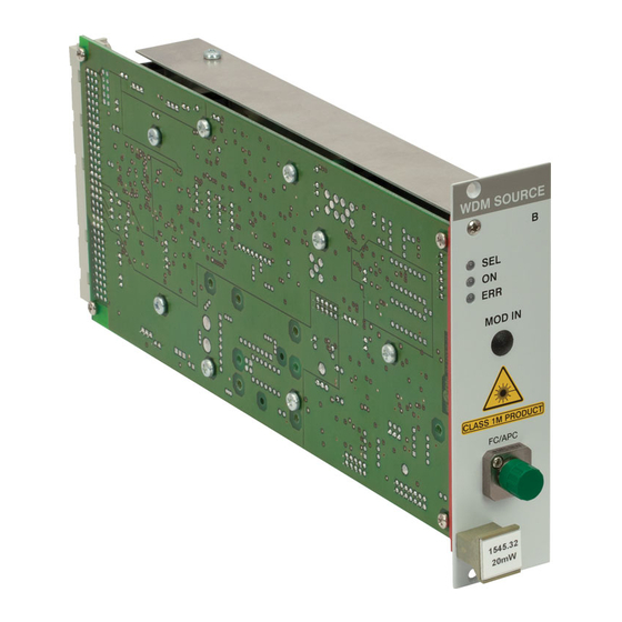
2.1 Operating elements on front panel 2 Operating the PRO8000 (-4) / PRO800 optical source modules 2.1 Operating elements on front panel LED display "module selected" LED display "module switched on" LED display "error" Modulation input (BNC or SMA) Optical output (FC/APC) Figure 1 Front view of WDM, CWDM and LS plug-in modules... -
Page 19: Connecting External Components
2.2 Connecting external components 2.2 Connecting external components 2.2.1 Connecting an optical fiber Depending on the construction of the optical connector the fiber is to be connected to the optical output by means of a corresponding plug. NOTE Do not to confuse the FC/PC with the FC/APC connector. The corresponding type of connector is marked on the module. -
Page 20: Modulating The Optical Source Modules
2.3 Modulating the optical source modules 2.3 Modulating the optical source modules The state of the art offers different procedures of modulation. Depending on the type ordered, the following kinds of modulation can be found within the different module types for analog or digital modulation (WDM, CWDM and LS types). WDM and CWDM types allow for synchronous modulation (on/off), 0...10 kHz, internal low frequency modulation (20 ... -
Page 21: Direct Modulation Via An Internal Bias-T
2.3 Modulating the optical source modules 2.3.1 Direct modulation via an internal bias-T The principal set up of a Pro8 optical module with direct modulation via an internal bias-T is shown here: DC Current control µ 0.1 F Modulation Input 50 Ω... - Page 22 2.3 Modulating the optical source modules Attention You have direct access to the expensive laser diode ! Be sure not to apply any transients Do not drive the laser diode with more than the rated maximum current! NOTES The modulation current is calculated as: / 50Ω...
- Page 23 2.3 Modulating the optical source modules 2.3.1.1 Remarks on direct modulation by bias-T Figure 3 Possible DC-component of digital signals Laser current with asymmetrical modulation When modulating via a BIAS-T only the AC component of the modulating signal is fed to the laser diode. The lower frequency limit of the modulation input is at about 100 ...
-
Page 24: Direct Modulation Via Internal Dc Bias-T
2.3 Modulating the optical source modules 2.3.2 Direct modulation via internal DC bias-T Here the set up of a Pro8 optical module with direct modulation via internal DC bias-T is shown: DC Current control Modulation Input 50 Ω Figure 4 Direct modulation via internal DC bias-T The injection current is directly modulated via internal bias-T. - Page 25 2.3 Modulating the optical source modules NOTES The laser is DC-coupled to the input so any input voltage will alter laser current and laser power. We recommend using an external coupling capacitor in cases, where no DC-coupling is required. The modulated laser diode current is calculated as: + (V ) / 50Ω...
- Page 26 2.3 Modulating the optical source modules Polarities of currents and voltages: Cathode Grounded DC Laser Current Modulation Input LD CW 50 Ω LD mod Figure 5 Polarities of currents and voltages with grounded cathode Anode Grounded DC Laser Current LD CW Modulation Input 50 Ω...
- Page 27 2.3 Modulating the optical source modules FURTHER NOTES Please do not shortcut the modulation input, as this is an „input voltage“ of 0V influencing the laser diode current (see formula). The laser diode is operated in constant current mode, so the output power is dependent on the temperature and thus on the wavelength.
-
Page 28: External Modulation (Pm-Output Recommended)
2.3 Modulating the optical source modules 2.3.3 External modulation (PM-output recommended) If there are still higher requirements regarding the transmission bandwidth at present only external electro-optical modulators are used. Their inner structure mostly resembles a Mach-Zehnder interferometer. Laser Input Laser Output Modulation Input Figure 7 External modulation generation... -
Page 29: Coherence Control
2.4 Coherence control 2.4 Coherence control The PRO8000 (-4) / PRO800 optical source modules (WDM, CWDM) are equipped with an adjustable coherence control, to reduce unwanted stimulated Brillouin or Raman Scattering. Coherence control is done by an internal amplitude modulation with band limited (1-5 kHz) white noise or with a discrete modulation with a sinusoidal, rectangular or triangular (option) signal in the frequency range 20 Hz …... -
Page 30: Operating The Wdm And Cwdm Modules
2.5 Operating the WDM and CWDM modules 2.5 Operating the WDM and CWDM modules 2.5.1 Functions in the main menu 2.5.1.1 Display The main menu shows the channel number, the wavelength and the status of the different inserted modules.: channel no. cursor wavelength state... - Page 31 2.5 Operating the WDM and CWDM modules 2.5.1.3 Switching modules on and off Modules can be switched on or off in the main menu or in the channel menu. For this purpose first select the module (see page 24). Press the key to turn on the module.
- Page 32 2.5 Operating the WDM and CWDM modules δT 2.5.1.4 Setting of temperature and optical power To set the wavelength or the optical output power in the main menu the correspond- ing module is selected with the cursor (here: CH1): CH1 1559.31 +3.00dBm CH2 -0.12°C TUNE (TUNE)
-
Page 33: Error Messages
2.5 Operating the WDM and CWDM modules 2.5.2 Error messages Error messages are shown in the bottom line of the display regardless of which menu you are in. If an error occurs, the display shows for example: Po = +0.00dBm LD on Po =1.0000 mW δT =+0.150 °C... - Page 34 2.5 Operating the WDM and CWDM modules b) Display messages while changing parameters: NO PAV TUNE ! Attempt to change the set power with modulation NOT IF MOD ON Attempt to change the modulation type while modulation is on. AMP TOO HIGH! Attempt to switch on modulation when either the sum of set power and modulation amplitude would exceed 100% nominal power or the difference be-...
-
Page 35: Functions In The Channel Menu (Cw Modules)
2.5 Operating the WDM and CWDM modules 2.5.3 Functions in the channel menu (CW modules) You can reach the channel menu from the main menu by pressing the key Pressing again will lead you back to the main menu. 2.5.3.1 Display In the channel menu all parameters of the selected module will appear: channel no. - Page 36 2.5 Operating the WDM and CWDM modules 2.5.3.2 Setting the wavelength Select the respective line with the cursor: λ =1552.524nm LD on f =193.100THz -3.00dBm CHANGE Press (CHANGE) to change the wavelength. Adjust the wavelength with the tuning knob. The actual wavelength follows your input. Press to finish the wavelength tuning and saves the data even if the PRO800/PRO8000 (-4) is switched off.
- Page 37 2.5 Operating the WDM and CWDM modules 2.5.3.4 Setting the optical power You can set the optical power either in dBm or in mW. Both power values are given in the channel menu. Changing one will also affect the display of the other. Select the respective line with the cursor: f =193.100THz LD on...
- Page 38 2.5 Operating the WDM and CWDM modules 2.5.3.6 Switching the modulations on and off 4.000mW LD off SYNCmod = ON SYN+LF LFmod = ON CHANGE Status field The CW modules can use two type of modulations: external synchronous modulation and internal low frequency modulation. Both can be applied one by one or together. SYNCmod The line: ' ' allows to switch on or off the synchronous modulation for every...
- Page 39 2.5 Operating the WDM and CWDM modules 2.5.3.7 Changing waveform and amplitude of LF modulation You can select between four different modulation waveforms in the line 'LFmod': sine – square – pulse-- (optional triang) and noise. (The Lfmod must be switched off, in order to change the modulation type).
-
Page 40: Functions In The Channel Menu (Modules With Direct Modulation)
2.5 Operating the WDM and CWDM modules 2.5.3.9 Display the serial number of the unit The last line of the menu shows the serial number, here CW module #1030-003. 2.5.4 Functions in the channel menu (modules with direct modulation) You can reach the channel menu from the main menu by pressing the key Pressing again will lead you back to the main menu. - Page 41 2.5 Operating the WDM and CWDM modules 2.5.4.2 Setting the wavelength Select the respective line with the cursor: λ =1552.524nm LD on f =193.100THz -3.00dBm CHANGE Press (CHANGE) to change the wavelength. Adjust the wavelength with the tuning knob. Press to make settings valid.
- Page 42 2.5 Operating the WDM and CWDM modules 2.5.4.4 Setting the optical power You can set the optical power either in dBm or in mW. Both power values are given in the channel menu. Changing one will also affect the display of the other. Select the respective line with the cursor: f =193.100THz LD on...
- Page 43 2.5 Operating the WDM and CWDM modules 2.5.4.6 Switching the external RF modulation on and off Vth=-1.3000V LD off HFmod = ON MOD HF Hfamp= 100% CHANGE Status field Pressing (CHANGE) toggles the status of the external RF modulation between on and off.
- Page 44 2.5 Operating the WDM and CWDM modules 2.5.4.8 Switching the modulations on and off HFamp = LD off SYNCmod = ON SYN+LF LFmod = ON CHANGE Status field The WDM CW modules can use two kinds of modulations: external synchronous modulation and internal low frequency modulation.
- Page 45 2.5 Operating the WDM and CWDM modules 2.5.4.9 Changing waveform and amplitude of LF modulation You can select between four different modulation waveforms in the line 'LFmod': Sine – Square – Pulse –(triangle, optional) and noise. (The Lfmod must be switched off, in order to change the modulation type).
-
Page 46: Functions In The Channel Menu (Wdmias-T-Dc Or Rf)
2.5 Operating the WDM and CWDM modules 2.5.5 Functions in the channel menu (WDMias-T-DC or RF) You can reach the channel menu from the main menu by pressing the key Pressing again will lead you back to the main menu. 2.5.5.1 Display In the channel menu all parameters of the selected module will appear:... - Page 47 2.5 Operating the WDM and CWDM modules 2.5.5.2 Setting the wavelength Select the respective line with the cursor: λ =1552.524nm LD on f =193.100THz -3.00dBm CHANGE Press (CHANGE) to change the wavelength. Adjust the wavelength with the tuning knob. The actual wavelength follows your input. Press to finish the wavelength tuning and saves the data even if the PRO800/PRO8000 (-4) is switched off.
- Page 48 2.5 Operating the WDM and CWDM modules 2.5.5.4 Setting the optical power You can set the optical power either in dBm or in mW. Both power values are given in the channel menu. Changing one will also affect the display of the other. Select the respective line with the cursor: f =193.100THz LD on...
- Page 49 2.5 Operating the WDM and CWDM modules 2.5.5.6 Switching the modulations on and off 4.000mW LD off SYNCmod = ON SYN+LF LFmod = ON CHANGE Status field The WDM modules can use two types of modulations: external synchronous modulation and internal low frequency modulation. Both can be applied one by one or SYNCmod together.
- Page 50 2.5 Operating the WDM and CWDM modules 2.5.5.7 Changing waveform and amplitude of LF modulation You can select between four different modulation waveforms in the line 'LFmod': Sine – Square – Pulse –(triangle, optional) and noise. (The Lfmod must be switched off, in order to change the modulation type).
- Page 51 2.5 Operating the WDM and CWDM modules 2.5.5.9 Display the serial number of the unit The last line of the menu shows the serial number, here CCDM module #1030-003. with Bias-T option (CCBT). PRO8000 (-4)/800 optical sources / page 45...
-
Page 52: Operating The Ls Modules
2.6 Operating the LS modules 2.6 Operating the LS modules 2.6.1 Functions in the main menu 2.6.1.1 Display δT The main menu shows the channel number, the temperature (difference) and the state of the LS module: δT channel no. cursor temperature state CH1 +0.00°C... - Page 53 2.6 Operating the LS modules δT 2.6.1.3 Setting of temperature and optical power δT To set the temperature in the main menu the corresponding module is selected with the cursor (here: CH1): CH1 +0.01°C +5.00dBm CH2 -0.12°C TUNE Pressing the key (TUNE) will turn the cursor to the right.
- Page 54 2.6 Operating the LS modules 2.6.1.4 Switching on and off Modules can be switched on or off in the main menu or in the channel menu. First select the module (see previous page). Pressing will switch on the module. The LED “ON”...
-
Page 55: Error Messages
2.6 Operating the LS modules 2.6.2 Error messages Error messages are shown in the bottom line of the display regardless of which menu you are in. If an error occurs, the display shows for example: Po = +0.00dBm LD on Po =1.0000 mW δT =+0.150 °C <CH2 OTP... - Page 56 2.6 Operating the LS modules b) Display messages while changing parameters: NO PAV TUNE ! Attempt to change the set power with modulation NOT IF MOD ON Attempt to change the modulation type while modulation is on. AMP TOO HIGH! Attempt to switch on modulation when either the sum of set power and modulation amplitude would exceed 100% nominal power or the difference be-...
-
Page 57: Functions In The Channel Menu (Ls)
2.6 Operating the LS modules 2.6.3 Functions in the channel menu (LS) The channel menu is reached from the main menu by pressing . Pressing again will lead you back to the main menu. 2.6.3.1 Display In the channel menu all parameters of the selected module are shown: channel no. - Page 58 2.6 Operating the LS modules 2.6.3.2 Setting the optical power To set the optical power (either in dBm or in mW) in the channel menu the respective line is selected with the cursor: Po = +0.00dBm LD on Po =1.0000 mW δT =+0.150 °C CHANGE Po = +0.00dBm...
- Page 59 2.6 Operating the LS modules 2.6.3.4 Switching the synchronous modulation on and off δT =+0.150 °C LD off SYNCmod = ON 1030-003 CHANGE Status field The LS modules can use internal synchronous modulation. The line: ' SYNCmod allows to switch on or off the synchronous modulation for every WDM or LS module, which is applied at the BNC jack on the back panel of the PRO8 (0 ...
-
Page 60: Communication With A Control Computer
3.1 General notes on remote control 3 Communication with a control computer 3.1 General notes on remote control The description of the mainframe of the PRO8000 (-4) / PRO800 includes all instructions on how to prepare and execute the programming of the system via computer interface. -
Page 61: Nomenclature
3.1 General notes on remote control 3.1.1 Nomenclature Program messages (PC ⇒ PRO8000 (-4)) are written in inverted commas: "*IDN?" Response messages (PRO8000 (-4) ⇒ PC) are written in brackets: [:SLOT 1] 1.234 There is a decimal point: Parameters are separated with comma: "PLOT 2,0"... - Page 62 3.1 General notes on remote control Numeric response data Type 2 (<NR2>) Is a numerical value with or without sign in floating point notation without exponent. Examples: -1.1 or +1.1 or -22.1 or 14356.789432 (Refer to IEE488.2 (8.7.3)) Numeric response data Type 3 (<NR3>) Is a numerical value with or without sign in floating point notation with exponent with sign.
-
Page 63: Commands Of The Different Light Source Modules
3.2 Commands of the different light source modules 3.2 Commands of the different light source modules 3.2.1 Select the module slot ":SLOT <NR1>" Selects a slot for further programming <Nr1>=1…8 (PRO8000), 1…2 (PRO800) ":SLOT?" Queries the selected slot [:SLOT <NR1><LF>] NOTE There are different commands for the different options implemented in the WDM modules (e.g. -
Page 64: Wdm Modules With Cw Mode
3.2 Commands of the different light source modules 3.2.2 WDM Modules with CW mode 3.2.2.1 Programming the coherence control (in %) (These command are for compatibility with the old WDM modules. The new commands: see " :LFMOD " and " :LFAMP ") This command has the same function as:... - Page 65 3.2 Commands of the different light source modules 3.2.2.2 Programming the wavelength (LAMBDA) Programming: ":LAMBDA:SET <NR3>" Program the wavelength of module (in nm) Reading: ":LAMBDA:SET?" Read the wavelength of the module [:LAMBDA:SET <NR3><LF>] ":LAMBDA:MIN?" Read the minimum wavelength allowed [:LAMBDA:MIN <NR3><LF>] ":LAMBDA:MAX?"...
- Page 66 3.2 Commands of the different light source modules 3.2.2.4 Setting the laser frequency [THz] Programming: ":LASERFREQ:SET <NR3>" Setting laser frequency in THz Reading: ":LASERFREQ:SET?" Read the set laser frequency [:LASERFREQ:SET <NR3><LF>] ":LASERFREQ:MIN?" Read the minimum allowed frequency [:LASERFREQ:MIN <NR3><LF>] ":LASERFREQ:MAX?" Read the maximum allowed frequency [:LASERFREQ:MAX <NR3><LF>] 3.2.2.5...
- Page 67 3.2 Commands of the different light source modules 3.2.2.6 Selecting the modulation frequency Programming: ":LFFREQ:SET<NR3>" Select the modulation frequency [Hz] Reading: ":LFFREQ:SET?" Read selected modulation frequency [:LFFREQ:SET 3.939536E+003<LF>] ":LFFREQ:MIN?" Read minimum modulation frequency [:LFFREQ:MIN 2.000000E+001<LF>] ":LFFREQ:MAX?" Read maximum modulation frequency [:LFFREQ:MAX 5.000000E+004<LF>] 3.2.2.7...
- Page 68 3.2 Commands of the different light source modules 3.2.2.8 Programming the output power in dBm Programming: ":P_DBM:SET <NR3>" Program the output power of the module (in dBm) ":P_DBM:START <NR3>" Program the start value (in dBm) for ELCH ":P_DBM:STOP <NR3>" Program the stop value (in dBm) for ELCH Reading: ":P_DBM:SET?"...
- Page 69 3.2 Commands of the different light source modules 3.2.2.9 Programming the output power in Watt Programming: ":P_W:SET <NR3>" Program the output power of the module (in W) ":P_W:START <NR3>" Program the start value (in W) for ELCH ":P_W:STOP <NR3>" Program the stop value (in W) for ELCH Reading: ":P_W:SET?"...
- Page 70 3.2 Commands of the different light source modules 3.2.2.10 Activating the synchronous modulation Programming: ":SYNCMOD ON" Activate the participation of the module in synchronous modulation ":SYNCMOD OFF" Deactivate the participation of the module in synchronous modulation Reading: ":SYNCMOD?" [:SYNCMOD ON<LF>], [:SYNCMOD OFF<LF>] 3.2.2.11 Reading the module identification Reading:...
- Page 71 3.2 Commands of the different light source modules 3.2.2.12 Read maximum allowed HF modulation voltage Reading: ":VHFMAX:ACT?" Read maximum HF modulation voltage in Volt [:VHFMAX:ACT 2.000000E-001<LF>] PRO8000 (-4)/800 optical sources / page 65...
-
Page 72: Cwdm Modules
3.2 Commands of the different light source modules 3.2.3 CWDM Modules 3.2.3.1 Turning the laser on and off Programming: ":LASER ON" Turn the laser output on ":LASER OFF" Turn the laser output off Reading: ":LASER?" Read status of the laser output [:LASER ON<LF>] [:LASER OFF<LF>] 3.2.3.2... - Page 73 3.2 Commands of the different light source modules Setting the temperature difference δT [K] 3.2.3.4 Programming: Set the temperature difference δT ":DTEMP:SET <NR3>" Reading: ":DTEMP:SET?" Read the set temperature difference [:DTEMP:SET 10.939E+000<LF>] Read minimum allowed δT ":DTEMP:MIN?" [:DTEMP:MIN 1.000000E-001<LF>] Read maximum allowed δT ":DTEMP:MAX?"...
- Page 74 3.2 Commands of the different light source modules 3.2.3.6 Selecting the modulation frequency Programming: ":LFFREQ:SET<NR3>" Select the modulation frequency [Hz] Reading: ":LFFREQ:SET?" Read selected modulation frequency [:LFFREQ:SET 3.939536E+003<LF>] ":LFFREQ:MIN?" Read minimum modulation frequency [:LFFREQ:MIN 2.000000E+001<LF>] ":LFFREQ:MAX?" Read maximum modulation frequency [:LFFREQ:MAX 5.000000E+004<LF>] 3.2.3.7...
- Page 75 3.2 Commands of the different light source modules 3.2.3.8 Programming the output power in dBm Programming: ":P_DBM:SET <NR3>" Program the output power of the module (in dBm) ":P_DBM:START <NR3>" Program the start value (in dBm) for ELCH ":P_DBM:STOP <NR3>" Program the stop value (in dBm) for ELCH Reading: ":P_DBM:SET?"...
- Page 76 3.2 Commands of the different light source modules 3.2.3.9 Programming the output power in Watt Programming: ":P_W:SET <NR3>" Program the output power of the module (in W) ":P_W:START <NR3>" Program the start value (in W) for ELCH ":P_W:STOP <NR3>" Program the stop value (in W) for ELCH Reading: ":P_W:SET?"...
- Page 77 3.2 Commands of the different light source modules 3.2.3.10 Activating the synchronous modulation Programming: ":SYNCMOD ON" Activate the participation of the module in synchronous modulation ":SYNCMOD OFF" Deactivate the participation of the module in synchronous modulation Reading: ":SYNCMOD?" [:SYNCMOD ON<LF>], [:SYNCMOD OFF<LF>] 3.2.3.11 Reading the module identification Reading:...
-
Page 78: Wdm Modules With Direct Modulation Mode
3.2 Commands of the different light source modules 3.2.4 WDM Modules with direct modulation mode 3.2.4.1 Programming the modulation current I Programming: ":CMOD:SET <NR3>" Program modulation current in % Reading: ":CMOD:SET?" Read the modulation current [:CMOD:SET <NR3><LF>] ":CMOD:MIN?" Read the minimum modulation current [:CMOD:MIN <NR3><LF>] ":CMOD:MAX?"... - Page 79 3.2 Commands of the different light source modules 3.2.4.3 Programming the RF modulation amplitude [%] Programming: ":HFAMP:SET <NR3>" Program modulation amplitude in % Reading: ":HFAMP:SET?" Read the modulation amplitude [:HFAMP:SET <NR3><LF>] ":HFAMP:MIN?" Read the minimum modulation amplitude [:HFAMP:MIN <NR3><LF>] ":HFAMP:MAX?" Read the maximum modulation amplitude [:HFAMP:MAX <NR3><LF>] 3.2.4.4...
- Page 80 3.2 Commands of the different light source modules 3.2.4.5 Programming the wavelength (LAMBDA) Programming: ":LAMBDA:SET <NR3>" Set the wavelength of the module (in nm) Reading: ":LAMBDA:SET?" Read the wavelength of the module [:LAMBDA:SET <NR3><LF>] ":LAMBDA:MIN?" Read the minimum wavelength allowed [:LAMBDA:MIN <NR3><LF>] ":LAMBDA:MAX?"...
- Page 81 3.2 Commands of the different light source modules 3.2.4.7 Setting the laser frequency (THz) Programming: ":LASERFREQ:SET <NR3>" Setting laser frequency in THz Reading: ":LASERFREQ:SET?" Read the set laser frequency [:LASERFREQ:SET <NR3><LF>] ":LASERFREQ:MIN?" Read the minimum allowed frequency [:LASERFREQ:MIN <NR3><LF>] ":LASERFREQ:MAX?" Read the maximum allowed frequency [:LASERFREQ:MAX <NR3><LF>] 3.2.4.8...
- Page 82 3.2 Commands of the different light source modules 3.2.4.9 Selecting the modulation frequency Programming: ":LFFREQ:SET<NR3>" Select modulation frequency Reading: ":LFFREQ:SET?" Read selected modulation frequency [:LFFREQ:SET 3.939536E+003<LF>] ":LFFREQ:MIN?" Read minimum modulation frequency [:LFFREQ:MIN 2.000000E+001<LF>] ":LFFREQ:MAX?" Read maximum modulation frequency [:LFFREQ:MAX 5.000000E+004<LF>] 3.2.4.10 Selecting the modulation type Programming: ":LFMOD:ENABLE ON"...
- Page 83 3.2 Commands of the different light source modules 3.2.4.11 Programming modulation Programming: ":MOD ON" Enable modulation ":MOD OFF" Disable modulation Reading: ":MOD?" Read status of modulation (on / off) [:MOD ON<LF>] [:MOD OFF<LF>] 3.2.4.12 Reading the actual average laser power (dBm) Reading ":PAV_DBM:ACT?"...
- Page 84 3.2 Commands of the different light source modules 3.2.4.14 Programming the output power in dBm Programming: ":P_DBM:SET <NR3>" Program the output power (in dBm) ":P_DBM:START <NR3>" Program the start value (in dBm) for ELCH ":P_DBM:STOP <NR3>" Program the stop value (in dBm) for ELCH Reading: ":P_DBM:SET?"...
- Page 85 3.2 Commands of the different light source modules 3.2.4.15 Programming the output power in Watt Programming: ":P_W:SET <NR3>" Program the output power (in W) ":P_W:START <NR3>" Program the start value (in W) for ELCH ":P_W:STOP <NR3>" Program the stop value (in W) for ELCH Reading: ":P_W:SET?"...
- Page 86 3.2 Commands of the different light source modules 3.2.4.16 Activating the synchronous modulation Programming: ":SYNCMOD ON" Activate the participation of the module in synchronous modulation ":SYNCMOD OFF" Deactivate the participation of the module in synchronous modulation Reading: ":SYNCMOD?" [:SYNCMOD ON<LF>], [:SYNCMOD OFF<LF>] 3.2.4.17 Reading the module identification Reading:...
- Page 87 3.2 Commands of the different light source modules 3.2.4.18 Programming the ECL logical level Uth (V) Programming: ":VTH:SET <NR3>" Program the ECL logical level (in V) Reading: ":VTH:SET?" Read the ECL logical level (in V) [:VTH:SET <NR3><LF>] ":VTH:MIN?" Read the minimum level voltage Uth allowed [:VTH:MIN <NR3><LF>] ":VTH:MAX?"...
-
Page 88: Wdm Modules With Bias-T
3.2 Commands of the different light source modules 3.2.5 WDM Modules with Bias-T 3.2.5.1 Programming the coherence control (in %) (This command is for compatibility with the old WDM modules. The new commands: see " :LFMOD " and " :LFAMP ") This command has the same function as: :LFMOD:TYPE NOISE... - Page 89 3.2 Commands of the different light source modules 3.2.5.2 Programming the wavelength (LAMBDA) Programming: ":LAMBDA:SET <NR3>" Program the wavelength of the module (in m) Reading: ":LAMBDA:SET?" Read the wavelength of the module [:LAMBDA:SET <NR3><LF>] ":LAMBDA:MIN?" Read the minimum wavelength allowed [:LAMBDA:MIN <NR3><LF>] ":LAMBDA:MAX?"...
- Page 90 3.2 Commands of the different light source modules 3.2.5.4 Setting the laser frequency [THz] Programming: Programming: ":LASERFREQ:SET <NR3>" Setting laser frequency in THz Reading: ":LASERFREQ:SET?" Read the set laser frequency [:LASERFREQ:SET <NR3><LF>] ":LASERFREQ:MIN?" Read the minimum allowed frequency [:LASERFREQ:MIN <NR3><LF>] ":LASERFREQ:MAX?"...
- Page 91 3.2 Commands of the different light source modules 3.2.5.6 Selecting the modulation frequency Programming: ":LFFREQ:SET<NR3>" Select modulation frequency Reading: ":LFFREQ:SET?" Read selected modulation frequency [:LFFREQ:SET 3.539536E+003<LF>] ":LFFREQ:MIN?" Read minimum modulation frequency [:LFFREQ:MIN 2.000000E+001<LF>] ":LFFREQ:MAX?" Read maximum modulation frequency [:LFFREQ:MAX 5.000000E+004<LF>] 3.2.5.7 Selecting the modulation type Programming:...
- Page 92 3.2 Commands of the different light source modules 3.2.5.8 Programming the output power in dBm Programming: ":P_DBM:SET <NR3>" Program the output power (in dBm) ":P_DBM:START <NR3>" Program the start value (in dBm) for ELCH ":P_DBM:STOP <NR3>" Program the stop value (in dBm) for ELCH Reading: ":P_DBM:SET?"...
- Page 93 3.2 Commands of the different light source modules 3.2.5.9 Programming the output power in Watt Programming: ":P_W:SET <NR3>" Program the output power (in W) ":P_W:START <NR3>" Program the start value (in W) for ELCH ":P_W:STOP <NR3>" Program the stop value (in W) for ELCH Reading: ":P_W:SET?"...
- Page 94 3.2 Commands of the different light source modules 3.2.5.10 Activating the synchronous modulation Programming: ":SYNCMOD ON" Activate the participation of the module in synchronous modulation ":SYNCMOD OFF" Deactivate the participation of the module in synchronous modulation Reading: ":SYNCMOD?" [:SYNCMOD ON<LF>], [:SYNCMOD OFF<LF>] 3.2.5.11 Reading the module identification Reading:...
-
Page 95: Ls Modules
3.2 Commands of the different light source modules 3.2.6 LS modules δT 3.2.6.1 Programming the temperature Programming: δT ":DTEMP:SET <NR3>" Program the temperature deviation Reading: δT ":DTEMP:SET?" Read the temperature deviation [:DTEMP:SET <NR3><LF>] ":DTEMP:MIN?" Read the minimum allowed temperature δT deviation [:DTEMP:MIN <NR3><LF>] ":DTEMP:MAX?"... - Page 96 3.2 Commands of the different light source modules 3.2.6.3 Programming the output power (in dBm) Programming: ":P_DBM:SET <NR3>" Program the output power (in dBm) ":P_DBM:START <NR3>" Program the start value (in dBm) for ELCH ":P_DBM:STOP <NR3>" Program the stop value (in dBm) for ELCH Reading: ":P_DBM:SET?"...
- Page 97 3.2 Commands of the different light source modules 3.2.6.4 Programming the output power (in W) Programming: ":P_W:SET <NR3>" Program the output power (in W) ":P_W:START <NR3>" Program the start value (in W) for ELCH ":P_W:STOP <NR3>" Program the stop value (in W) for ELCH Reading: ":P_W:SET?"...
- Page 98 3.2 Commands of the different light source modules 3.2.6.5 Activating the synchronous modulation Programming: ":SYNCMOD ON" Activate the participation of the module in synchronous modulation ":SYNCMOD OFF" Deactivate the participation of the module in synchronous modulation Reading: ":SYNCMOD?" [:SYNCMOD ON<LF>], [:SYNCMOD OFF<LF>] 3.2.6.6 Reading the module identification...
-
Page 99: Status Reporting
3.3 Status reporting 3.3 Status reporting The WDM8xxxx, C81xxx and LS8xxxx modules provide three 16 bit registers DEC, DEE and EDE (see Figure 8) and four 8 bit registers ESR, STB, ESE and SRE (see Figure 9) to program various service request functions and status reporting. (Please refer to the IEEE488.2-1992 standard chapter 11) (:STAT:DECn?) n: Slot number... - Page 100 3.3 Status reporting Output buffer ERROR Queue or serial poll Service Request Generation Figure 9 The 8-Bit registers “ESR, STB, ESE and SRE” PRO8000/800 optical sources / page 94...
-
Page 101: Standard Event Status Register (Esr)
3.3 Status reporting 3.3.1 Standard event status register (ESR) The bits of this register represent the following standard events: Power on This event bit indicates that an off to on transition has occurred in the power supply. So it is high after turning on the device for the first time. -
Page 102: Status Byte Register (Stb)
3.3 Status reporting 3.3.3 Status byte register (STB) The bits of this register are showing the status of the LDC 3065. RQS: Request service message: Shows that this device has asserted SRQ (red via serial poll). Master summary status: Shows that this device requests a "*STB?"... -
Page 103: Reading The Stb By Detecting Srq
3.3 Status reporting 3.3.5 Reading the STB by detecting SRQ If an SRQ is asserted (see 3.3.4) bit 6 of the STB is set to logical 1, so that the controller can detect which device asserted the SRQ by auto serial polling. 3.3.6 Reading the STB by *STB? command If the controller does not "listen"... -
Page 104: Device Error Condition Register (Dec)
3.3 Status reporting 3.3.8 Device error condition register (DEC) The bits of this register show the errors that occur during operation (operation errors). The bits are active high. If the error disappears, the bits are reset to low. For PRO8000 (-4)/800 optical source modules bits 0, 2 ... 4 and 8 are used: (0) Over temperature Laser temperature too high. -
Page 105: Device Error Event Enable Register (Ede)
3.3 Status reporting 3.3.10 Device error event enable register (EDE) The bits of the EDE are used to select which bits of the DEE shall influence bit 3 (DES) of the STB. The 8 bits of the EDE are related to the according 8 bits of the DEE by logical "AND". -
Page 106: Error Messages
Module temperature too high. Switch off the output and wait until the module has cooled down. Maintain proper air flow. [1202,"Internal power failure"] Possible reason: Severe hardware error. Contact Thorlabs. [1203, "Temperature is out of window"] Possible reason: The operating temperature of the laser module is not yet reached while attempting to switch on the module. - Page 107 3.4 Error messages [1282,"No power change during modulation on allowed "] Possible reason: Attempt to change the output power with the modulation switched on (only DIR modules) [1284,"Calibration required "] Possible reason: Loss of calibration data. Should not occur in normal operation [1285,"No LF-modulation type change during LF-modulation on allowed "] Possible reason: Attempt to change the modulation type while the modulation is...
-
Page 108: Service And Maintenance
4.1 Recalibration of laser wavelength If the precise laser wavelength is of vital interest to you, you should send your module for recalibration to Thorlabs (Germany) once a year! 4.2 Shutter function control If your module is equipped with a shutter, you should regularly control the correct function of the shutter. -
Page 109: Troubleshooting
4.3 Troubleshooting 4.3 Troubleshooting In case that one module of your PRO8000/800 system shows malfunction please check the following items: Module does not work at all (no display on the mainframe): Mainframe PRO8000 (-4)/800 connected properly to the mains? Connect the PRO8000 (-4)/800 to the power line, take care of the right voltage setting of your mainframe. - Page 110 If you don’t find the error source by means of the trouble shooting list or if more modules work erratic please first connect Thorlabs-Hotline (blueline@thorlabs.com) before sending the whole PRO8000 (-4)/800 system for checkup and repair to Thorlabs-Germany. (refer to section 5.5, “Addresses ” on page 112 PRO8000/800 optical sources / page 104...
-
Page 111: Appendix
5.1.1 Waste treatment on your own responsibility If you do not return an “end of life” unit to Thorlabs, you must hand it to a company specialized in waste recovery. Do not dispose of the unit in a litter bin or at a public waste disposal site. -
Page 112: Ecological Background
5.1 Thorlabs “End of Life” policy (WEEE) 5.1.2 Ecological background It is well known that WEEE pollutes the environment by releasing toxic products during decomposition. The aim of the European RoHS directive is to reduce the content of toxic substances in electronic products in the future. -
Page 113: List Of Acronyms And Abbreviations
5.2 List of acronyms and abbreviations 5.2 List of acronyms and abbreviations The following abbreviations are used in this manual: Alternating Current Anode Ground Amplified Spontaneous Emission Angled Physical Contact Direct Current Device Error Condition Register Device Error Event Register Device Error Status Distributed Feedback Electro-Absorption... - Page 114 5.2 List of acronyms and abbreviations SLED Super LED, Super Light Emitting Diode Service Request Enable Register Service ReQuest STatus Byte Register ThermoElectric Cooler (Peltier Element) Transistor-Transistor Logic Wavelength Division Multiplex PRO8000/800 optical sources / page 108...
-
Page 115: List Of Figures
5.3 List of figures 5.3 List of figures Figure 1 Front view of WDM, CWDM and LS plug-in modules Figure 2 Direct modulation via internal bias-T Figure 3 Possible DC-component of digital signals Figure 4 Direct modulation via internal DC bias-T Figure 5 Polarities of currents and voltages with grounded cathode Figure 6... -
Page 116: Certifications And Compliances
Compliance demonstrated using high-quality shielded interface cables. Compliance demonstrated with the WDM8x, C81x, and LS8x series modules installed in the Thorlabs GmbH PRO8x series of mainframes. Test configuration included a Thorlabs GmbH POL8000 Polarization Controller. Emissions, which exceed the levels required by these standards, may occur when this equipment is connected to a test object. - Page 117 5.4 Certifications and compliances Certifications and compliances Category Standards or description Complies with EN60825-1/A2:2001 Safety of laser products Part 1. Equipment classification, requirements and user’s guide. Class 1M IEC60825-1/A2:2001 Safety of laser products Part 1. Equipment classification, requirements and user’s guide. Class 1M 21CFR 1040.10 Code of Federal Regulations,...
-
Page 118: Addresses
5.5 Addresses 5.5 Addresses Our Company is represented by several distributors and sales offices throughout the world. Europe Thorlabs GmbH Gauss-Strasse 11 D-85757 Karlsfeld Germany Sales and Support Phone: +49 (0) 81 31 / 5956-0 Fax: +49 (0) 81 31 / 5956-99 Email: europe@thorlabs.com... - Page 119 5.5 Addresses Japan Thorlabs, Inc. 6th Floor, Fujimizaka Building 5-17-1, Ohtsuka Bunkyo-ku, Tokyo 112-0012 Japan Sales and Support Phone: +81-3-5977-8401 Fax: +81-3-5977-8402 Email: sales@thorlabs.jp Web: www.thorlabs.jp Please call our hotlines, send an Email to ask for your nearest distributor or just visit our homepage http://www.thorlabs.com...
Need help?
Do you have a question about the Blueline Series and is the answer not in the manual?
Questions and answers