Advertisement
INSTALLATION AND MAINTENANCE INSTRUCTIONS
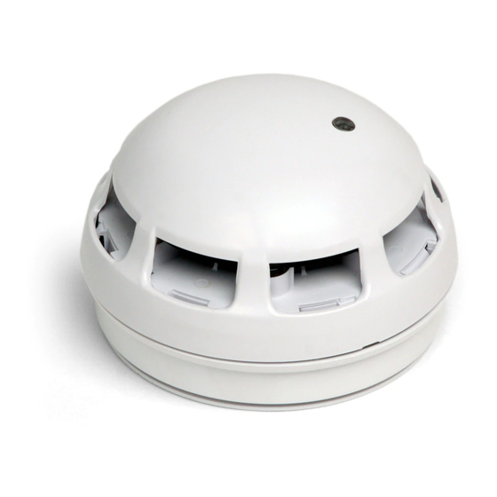
204-0003 Twinflex Multipoint ASD Detector,
204-0001 Twinflex Multipoint ASD with Sounder,
204-0012 Twinflex Multipoint ASD with Sounder / Strobe
General Description
The Twinflex Multipoint ASD is a plug-in type smoke detector that utilises a photo-
electric sensing chamber to make a measurement corresponding to smoke density.
The device also incorporates a thermistor sensing circuit to allow for accurate heat
measurement. These elements allow the device to be configured to a smoke, heat or
combined setting. This device is only compatible with the Twinflex control panels (and
their associated detection and alarm equipment) and may also incorporate a sounder
beacon (ignore all references to sounders/beacons if your device has no
sounder/beacon).
Before Installation
The detector must be installed in compliance with the control panel installation
manual. The installation must also meet the requirements of any local authority. For
maximum performance the detector should be installed in compliance with BS5839-
1:2013.
Spacing
Fike recommends spacing detectors in accordance with BS5839-1:2013. Due to the effects of IR and possible magnetic
interference, detectors should not be fitted any closer than 500mm (preferably 1000mm) to a light fitting or any other source of IR or
EMI. In addition to this recommendation the device should be mounted so that the indication LED is facing towards the light fitting.
For more specific information regarding detector spacing, placement and special applications please refer to BS5839-1:2013.
Note: As with other optical detectors, this device should not be located where subjected to high levels or pulses of light or infra red
light, as this may cause false alarms or faults.
Detector Installation
All wiring must be installed in compliance with the recommendations laid out by BS5839-1:2013 as well as any special
recommendations documented in the control panel installation manual. The cabling used should be of a 2-core 1.5mm
fire resistant type (e.g. FP200 equivalent), and is to be wired in the form of a screened 2-core radial circuit (with no spurs) from the
control panel, terminating at the last ("End of Line") device.
Fix the detector base in a suitable horizontal position using the two screw slots provided, remembering to allow enough cable
length for termination. You may then terminate your cables directly into the terminal block according to the terminal labels. It is
important to maintain the screen continuity in order to protect against data corruption from interference.
Connections
Terminal
1
REM LED –
2
ZONE +
3
0V
4
Not Fitted
5
Not Fitted
SCRN
SCRN
Description
Remote LED 0V (-VE)
Zone In/Out +VE and Remote
LED +VE
Zone In/Out 0V
N/A
N/A
Screen
2
screened,
26-0947 Issue 10
31/07/18
Advertisement
Table of Contents

Related Manuals for Fike 204-0003 Twinflex Multipoint ASD


Summary of Contents for Fike 204-0003 Twinflex Multipoint ASD
- Page 1 Spacing Fike recommends spacing detectors in accordance with BS5839-1:2013. Due to the effects of IR and possible magnetic interference, detectors should not be fitted any closer than 500mm (preferably 1000mm) to a light fitting or any other source of IR or EMI.
- Page 2 Twinflex Multipoint ASD Detectors can be mixed on the same zone as other types of Twinflex device (e.g. Twinflex Call-points and earlier detectors). If mixed with earlier detectors, the zone must be set to ‘CP/DET’ and not ‘CP/SM/HT’. The above diagram shows how to make the zone positive, zone negative and screen connections between the control panel and Twinflex Multipoint ASD Detectors.
- Page 3 DIL SWITCH SETTINGS EOL Signal Disabled (no end of line signal) Enabled Detection Mode Disabled (no detection) Smoke 1 – Standard optical with high thermal enhancement Smoke 2 – Standard optical with normal thermal enhancement Smoke 3**– Low sensitivity optical with transient rejection Heat 1 –...
- Page 4 Pass conditions Operational reliability Pass Fike’s policy is one of continual improvement and the right to change Tolerance to supply voltage Pass a specification at any time without notice is reserved. Whilst every Durability of operational reliability and response delay,...
Need help?
Do you have a question about the 204-0003 Twinflex Multipoint ASD and is the answer not in the manual?
Questions and answers