Table of Contents
Advertisement
Advertisement
Table of Contents

Related Manuals for MEI CASHFLOW 9520


Summary of Contents for MEI CASHFLOW 9520
- Page 1 CASHFLOW ® 9520 / 9524 / 9528 SELECTOR SYSTEMS DESIGN GUIDE MEI., 2003 Rev: G1...
- Page 2 , CashFlow and the MEI device are registered trademarks. MEI reserves the right to change the product or the product specifications at any time. While every effort has been made to ensure that the information in this publication is accurate, MEI disclaims any liability for any direct or indirect losses (howsoever caused) arising out of use or reliance on this information.
-
Page 3: Table Of Contents
1) ..................21 ACHINE INTERFACE CONNECTOR ONNECTOR 4) ......................21 YNAMIC ROUTE INHIBIT ONNECTOR ) .......................22 UPPORT ONNECTOR (10 - ).......................22 ERIAL ONNECTOR ROUTING CONFIGURATION ........................23 ...........................23 OUTING RIORITY 4, D ......................24 ONNECTOR YNAMIC OUTE NHIBIT MEI., 2003 Page Rev: G1... - Page 4 LAMMABILITY ........................42 OWER UPPLY NPUT ROTECTION ............................42 ECHANICAL ARTS ................................42 IZES ..........................42 CCEPTANCE ENVIRONMENTAL PERFORMANCE ......................43 ............................43 EMPERATURE ANGE .............................43 UMIDITY ANGE .......................43 EMPERATURE UMIDITY SPECIFICATION ...............................44 HERMAL SHOCK TRANSPORTATION ............................45 PRODUCT SUPPORT ............................46 MEI., 2003 Page Rev: G1...
-
Page 5: Safety
Warning: This is a class A product. In a domestic environment this product may cause radio interference, in which case the user may be required to take adequate measures. MEI., 2003 Page Rev: G1... -
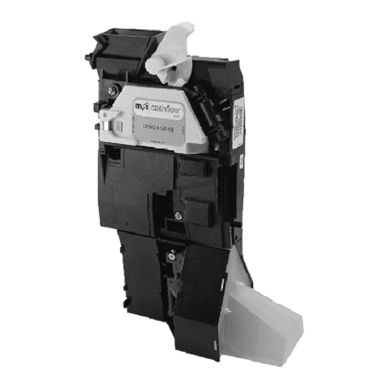
Page 6: Product Identification
9520 / 9524 / 9528 Design Guide PRODUCT IDENTIFICATION MEI has manufactured coin mechanisms compatible with gaming and amusement machines for a number of years. Over this time the functionality of the range has been enhanced to match the market needs and whilst maintaining mechanical compatibility. -
Page 7: Product Options; Front Plates
It is supplied standard coin entry complete with a coin It is not supplied with bezel assembly. catcher hoop, a coin a coin catcher hoop. entry bezel and a coin mechanism mounting plate assembly. MEI., 2003 Page Rev: G1... -
Page 8: Product Options; Reject Covers
Rejected coins are routed to Rejected coins are routed to Rejected coins are routed to the bottom centre of the the bottom left of the reject the left-hand side of the reject cover. cover. reject cover. MEI., 2003 Page Rev: G1... -
Page 9: Product Build Options
9520 / 9524 / 9528 Design Guide Product Build Options Each product variant is made from the following components: Side Entry Product 7802 Front Plate Side Entry Validator 7804 Front Plate 7805 Front Plate CF9524 4-way Separator 7819 Front Plate MEI., 2003 Page Rev: G1... - Page 10 9520 / 9524 / 9528 Design Guide Top Entry Product Coin Entry/Token Entry Bezel (with electrics) CF9524/8 Y-Chute CF9524/8 Top Entry Validator Metal Channel CF9528 Short Channel (Supplied by machine manufacturer Manifold 4-way Separator 8-way Separator Tube Collar Plate MEI., 2003 Page Rev: G1...
-
Page 11: Description & Operation
Support Tool Connector (CPM) CashFlow Programming Module Route Inhibit Connector Serial Interface Connector (HII) Separator Connector 8-way DIP Switch Post Gate Strobes Dual Polarity and BCO Interface Connector Pre-Gate Strobes Validator Lid Reject Lever MEI., 2003 Page Rev: G1... -
Page 12: Coin Entry (1)
LED. Support Tool Connector (CPM) (4) ® This 6-way connector is used for a MEI Support Tools, such as the CPM (CashFlow programming Module). Route Inhibit Connector (5) This is a 9-pin connector that provides input from the machine to the validator. Its function is to modify coin routing. -
Page 13: Post -Gate Strobes (9)
It is also used in some product configuration modes. Reject Lever (13) This lever can be pressed to clear any coins that might have got stuck inside the validator lid. MEI., 2003 Page Rev: G1... -
Page 14: Product Interfaces
Negative common operation is selected when pin 2 output common is between 0V to +1.0V. Positive common is selected when pin 2 is greater than +7.0 volts (Max 12V) with respect to pin 11. MEI., 2003 Page Rev: G1... -
Page 15: Binary Coded Output (Bco) - Uk
If this value is not active then the machine will ignore the codes. B, D, E and F become the 4 code states indicating which coin is accepted. MEI., 2003 Page Rev: G1... - Page 16 Parity. Coin outputs B, C, E and D become the 4 code states indicating which coin is accepted. (BCO - EURO) Coin Output Coin Value Coin 1 Coin 2 Coin 3 Coin 4 Coin 5 Coin 6 Coin 7 Coin 8 Coin 9 MEI., 2003 Page Rev: G1...
-
Page 17: Coin Validation Inhibits A, B, C, D, E, F
Coin Value Coin 1 Token 1 Coin 2 Token 2 Coin 3 Coin 4 Coin 5 Coin 6 Coin 7 Coin 8 Coin 9 Coin 10 Coin 11 X= RESERVED *= GROUPED INHIBIT INPUT MEI., 2003 Page Rev: G1... -
Page 18: Automatic Mode - Parallel Or Bco Selection
Interface connections are via a 17-way header from the standard PCB. This header is single row of 17 pins on a 0.1 inch x 0.1-inch grid, with a pin size of 0.025-inch square. The complete interface connector (connector 1) functions are shown on the next page. MEI., 2003 Page Rev: G1... -
Page 19: Electrical Interfaces
14 Inhibit 2 F Coin Inhibit 15 Inhibit 1 B Coin Inhibit 16 Inhibit 5 A Coin Inhibit 17 Inhibit 6 Connector types used:- 15 Way Molex SIL 6471 or 17 Way Molex SIL 6471. MEI., 2003 Page Rev: G1... -
Page 20: Separator Connector (2)
Note: (d) is the same route as D but has a higher priority. The CF9528 exit routes are marked as Route (1, 2, 3, 4, 5, 6 & 7) with (8) being the default exit route. Solenoid 3 Solenoid 2 Solenoid 1 9528 Route 9524 Route MEI., 2003 Page Rev: G1... -
Page 21: Machine Interface Connector (Connector 1)
Figure 2 Full 1 Full 2 Full 3 Full 4 Full 5 Full 6 Full 7 n.c. Ground (0v) Full = 0 to 1.0V wrt pin 9 Empty = +3.5V MEI., 2003 Page Rev: G1... -
Page 22: Support Tool Connector (6-Way)
Support Tool Connector (6-way) This connector can be found on the front of the acceptor and is used to reconfigure the ® validator using a MEI support tool e.g. (CPM) CashFlow Programming Module. Serial (HI ) Connector (10 - way) The position of this connector has been moved from the previous CF126 product and can now be found on the front face of the CF95xx. -
Page 23: Routing Configuration
(b), C, D or B. Therefore (d) and (c) cannot be used as a secondary route. CF9528 8-WAY Coin Route Priority SEPARATOR Highest Default Route = 8 Lowest The CF952x Series can support two types of separator, a 4-way and an 8-way. MEI., 2003 Page Rev: G1... -
Page 24: Connector 4, Dynamic Route Inhibit
Note: Care must be taken to apply a Route full signal to the correct pin. For example of Exit D is selected then the signal should be directed to Pin 6 (D). Likewise Pin 1 (d) should be used of Primary Route (d) is selected. MEI., 2003 Page Rev: G1... -
Page 25: Y-Chute Interface Connector
0 volts common input to Y-chute Polarisation Not Used Inhibit B Input Inhibit signal from the machine Inhibit C Input Inhibit D Input Inhibit E Input Inhibit F Input 12 Volts Input 12 volts input to the Y-chute MEI., 2003 Page Rev: G1... -
Page 26: Dual Entry System
NOTE: When an old, (pre-March 1997), Y chute is used with a BACTA standard machine interface (BCO) the mode of operation of the Y chute needs to be changed. (Consult with MEI technical support for further details). MEI., 2003... -
Page 27: Electrical Specification
F Polarity Sense Output Driver Block o/p common Output Circuit Block Diagram Absolute Maximum Ratings Output Current (O/PA) - F) ± 30 mA Maximum Voltage (O/PA) - F) ± 32 V w.r.t. 0V MEI., 2003 Page Rev: G1... -
Page 28: Output Common Specification
See the diagrams below for sample multiplexing implementation. If output common is changed form negative to positive common (or vice versa) during polling, the state of any coin output cannot be guaranteed for 15us. MEI., 2003 Page Rev: G1... - Page 29 = 100 milli-seconds (max) Coin Inhibits High = Coin inhibit Low = Coin enable Maximum input voltage to enable channels (logic 0) <1.0V Minimum input voltage to inhibit channels (logic 1) >4.0V Input impedance 12Kohms to +5v. MEI., 2003 Page Rev: G1...
-
Page 30: Positive Common Voltage Range
Switched on for between 80 and 120ms on acceptance of appropriate coin. 100ms max Vsupply Output Mode Select Output Common Output A T (o/p valid) Coin O/P valid BCO Output Indication from "Power ON" MEI., 2003 Page Rev: G1... -
Page 31: Negative Common Voltage Range
Coin Inhibits Input voltage to enable channels (logic 0) ) <1.0V Input voltage to inhibit channels (logic 1) >4.0V Input impedance 12 Kohms to +5v. MEI., 2003 Page Rev: G1... -
Page 32: Mechanical Interface Drawings
CF9528 Long Channel Mounting Space Envelope Drawing Number 35824 Long channel dimensions. Drawing Number 35954 CF9528 system installation dimensions. - (Fitted with Long manifold) Drawing Number 35961 CF9528 system installation dimensions. - (Fitted with Short manifold). MEI., 2003 Page Rev: G1... - Page 33 CashFlow 9520 / 9524 / 9528 Design Guide MEI., 2003 Page Rev: G1...
- Page 34 CashFlow 9520 / 9524 / 9528 Design Guide MEI., 2003 Page Rev: G1...
- Page 35 CashFlow 9520 / 9524 / 9528 Design Guide MEI., 2003 Page Rev: G1...
- Page 36 CashFlow 9520 / 9524 / 9528 Design Guide MEI., 2003 Page Rev: G1...
- Page 37 CashFlow 9520 / 9524 / 9528 Design Guide MEI., 2003 Page Rev: G1...
- Page 38 CashFlow 9520 / 9524 / 9528 Design Guide MEI., 2003 Page Rev: G1...
- Page 39 CashFlow 9520 / 9524 / 9528 Design Guide MEI., 2003 Page Rev: G1...
-
Page 40: Compatibility
CashFlow 9520 / 9524 / 9528 Design Guide COMPATIBILITY Previously Used New Product Equivalent ® CashFlow ® & CashFlow 9520 ® CashFlow ® ® CashFlow CashFlow 9524 ® ® CashFlow CashFlow 9528 MEI., 2003 Page Rev: G1... -
Page 41: Performance Standards
All major plastic parts will be moulded in materials with a flammability rating of 94 V-2 / IEC 707 FV2 or better. Some small parts are moulded in materials with a flammability rating of 94 HB / IEC 707 FH2. MEI., 2003 Page Rev: G1... -
Page 42: Power Supply Input Protection
>330 ms apart. After a coin has been rejected, no further coins will be accepted for a period of 0.5 seconds. Should a further coin be entered during this period, the reject period will be reinitiated. MEI., 2003 Page Rev: G1... -
Page 43: Environmental Performance
Temperature / Humidity specification Relative Humidity - 10,95 35, 95 35, 90 60, 10 - 10, 10 75, 10 Temperature • N = Normal operating range • F = Full operating range • S = Storage range MEI., 2003 Page Rev: G1... -
Page 44: Thermal Shock
10°C per hour, non condensing • Vibration (through machine mounting) • Vibration 0.25g at 5Hz to 500Hz - pseudo random, flat bandwidth • Coin validation will not be affected. MEI., 2003 Page Rev: G1... -
Page 45: Transportation
BS 2011 Part 2.1 b : 1977 Drop - Free Fall 2 drops from 1m onto each face BS 2011 Part 2.1 ED : 1977 Drop and Topple 50mm drop onto each corner BS2011 Part 2.1 EC : 1977 MEI., 2003 Page Rev: G1... -
Page 46: Product Support
CashFlow 9520 / 9524 / 9528 Design Guide PRODUCT SUPPORT In addition to the MEI offices around the world an international network of Distributors and Approved Service Centres can offer you technical support and other services as well. ® These services include repairs, re-programming of your Cashflow products with new coinsets, replacing damaged modules, and the supply of a range of spare parts. - Page 47 Namco House, Acton Park Estate BELGIUM The Vale, London W3 7QE L.M.C. Contact: Peter Murphy PLASSTRAAT 13 Tel: 020 8324 6212 1860, MEISE Fax: 020 8324 6125 Tel: +32 22 68 1369 Fax: +32 22 68 6502 MEI., 2002 Page Rev: G1...
- Page 48 CashFlow 9520 / 9524 / 9528 Design Guide HELPING YOU DELIVER YOUR REPRESENTATIVE...
Need help?
Do you have a question about the CASHFLOW 9520 and is the answer not in the manual?
Questions and answers