Table of Contents
Advertisement
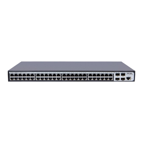
Preparing for installation
H3C S1850 switch series includes the following models:
•
S1850-10P
•
S1850-28P
•
S1850-28P-PWR
•
S1850-52P
Safety recommendations
CAUTION:
The switch is a class-A device and might cause
electromagnetic interference (EMI). Take actions to prevent
EMI as required.
To avoid any equipment damage or bodily injury, read the following
safety recommendations before installation.
•
Do not place the switch near water or in a damp environment.
Prevent water or moisture from entering the chassis.
•
Place the switch in a clean environment. Dust buildup on the
chassis might result in electrostatic adsorption, which reduces
lifespan of the device and can cause communication failure.
•
Keep the air inlet and outlet vents of the switch free of
obstruction, and do not stack switches.
•
Make sure the operating voltage is stable and in the required
range.
•
Before using the switch, ground it reliably by using the
grounding point on the rear panel.
1
Advertisement
Table of Contents

Related Manuals for H3C S1850 Series


Summary of Contents for H3C S1850 Series
-
Page 1: Preparing For Installation
Preparing for installation H3C S1850 switch series includes the following models: • S1850-10P • S1850-28P • S1850-28P-PWR • S1850-52P Safety recommendations CAUTION: The switch is a class-A device and might cause electromagnetic interference (EMI). Take actions to prevent EMI as required. -
Page 2: Installing The Switch
• Before cleaning the switch, remove the power cord from the switch. Do not clean the switch with a wet cloth or liquid. • Do not open the chassis while the switch is operating. To avoid damage, do not open the chassis even when the switch is powered off. - Page 3 Place the switch on a rack shelf in the rack. Slide the switch into the rack until the mounting brackets are flush against the front rack posts and the oval holes in the brackets align with the mounting holes in the front rack posts. Use screws to secure the mounting brackets to the front rack posts.
-
Page 4: Mounting The Switch On A Workbench
Figure 4 Mounting the switch in the rack (S1850-28P/S1850-28P-PWR/S1850-52P) NOTE: Mounting brackets are not used for bearing the weight of the switch. A rack shelf is required on the rack to bear the switch weight. Mounting the switch on a workbench Make sure the workbench is clean, sturdy, and reliably grounded. -
Page 5: Mounting The Switch On A Wall
Place the switch upside up on the workbench. Mounting the switch on a wall Only an H3C S1850-10P switch can be installed on a wall. The type of screws used to wall-mount the switch depends on the wall type. This section uses a concrete wall as an example. - Page 6 Figure 6 Hole spacing Insert one screw anchor into each hole until the anchors are flush with the wall surface. Drive one screw into each screw anchor, and tighten the screw to secure it in the wall anchor. Leave a minimum clearance of 1.5 mm (0.06 in) between the base of the screw head and the screw anchor so the switch can hang on the screws securely.
-
Page 7: Connecting The Console Cable
Align the two mounting holes in the switch chassis bottom with the two screws on the wall and hang the switch. Make sure the Ethernet ports are facing downwards and the chassis side panels are perpendicular to the ground. Figure 8 Wall-mounting the switch (1) Mounting hole in the switch chassis bottom Connecting cables Connecting the console cable... -
Page 8: Connecting The Grounding Cable
Figure 9 Connecting the console cable Connecting the grounding cable CAUTION: Correctly connecting the grounding cable is crucial to lightning protection and EMI protection. To connect the grounding cable: Use a Phillips screwdriver to remove the grounding screw from grounding hole in the rear panel of the chassis. Use the grounding screw to attach the ring terminal of the grounding cable to the grounding hole. -
Page 9: Connecting The Power Cord
Remove the hex nut from a grounding post on the grounding strip. Attach the loop to the grounding post and fasten the hex nut. Figure 10 Connecting the grounding cable Connecting the power cord Make sure the switch is reliably grounded. Connect one end of the AC power cord to the AC power receptacle on the switch. -
Page 10: Installing Sfp Transceiver Modules And Optical Fibers
Installing SFP transceiver modules and optical fibers CAUTION: • When you install or remove an SFP transceiver module, do not touch the golden plating on it. • Remove the dust plugs from an SFP transceiver module only when you are to connect optical fibers to the module. •... -
Page 11: Accessing The Switch
Figure 13 Installing optical fibers Accessing the switch The switch supports Web GUI management. To access the Web GUI of the switch: Connect the switch to a PC. Make sure the switch and PC are reachable to reach other. By default, the management IP address of the switch is 192.168.0.233 and the subnet mask is 255.255.255.0. -
Page 12: Troubleshooting
Power status LED off 2. Verify that the power switch is turned on. 3. If the issue persists, contact H3C Support. 1. Verify that the network cable is connected to the Ethernet port securely. 2. Connect the network cable to two Ethernet LAN port ports on the switch. -
Page 13: Appendix A Chassis Views And Technical Specifications
If these configurations exist, remove them. 3. Configure a local network address for the PC and then disable and enable the local network connection. 4. If the issue persists, contact H3C Support. Appendix A Chassis views and technical specifications Chassis views... - Page 14 Figure 16 S1850-28P Figure 17 S1850-28P-PWR Figure 18 S1850-52P (1) 10/100/1000BASE-T copper port (2) 100/1000BASE-X SFP fiber port (3) Console port (4) Port status LED (5) Power status LED (Power)
-
Page 15: Rear Panel
Rear panel Figure 19 S1850-10P Figure 20 S1850-28P Figure 21 S1850-28P-PWR/S1850-52P (1) Grounding screw (2) AC power receptacle (3) Security slot... -
Page 16: Technical Specifications
Technical specifications Table 2 Technical specifications S1850-1 S1850-28 S1850-52 S1850-2 Item 8P-PWR 44 × 266 44 × 440 44 × 440 × 44 × 440 × × 162 × 238 173 mm 238 mm Dimensions (1.73 × (1.73 × (H × W × D) (1.73 ×... - Page 17 S1850-1 S1850-28 S1850-52 S1850-2 Item 8P-PWR Connector type: RJ-45 Copper port Half/full duplex, auto-negotiation properties MDI/MDI-X Connector type: LC Fiber port properties 100/1000 Mbps, full duplex Power consumption 4.5 W 9.5 W 20 W 20 W (static) ≤ 235 W (includin Power g 190 W...
-
Page 18: Appendix B Leds
S1850-1 S1850-28 S1850-52 S1850-2 Item 8P-PWR Fire resistance UL60950-1/IEC60950-1/EN60950-1 compliance Appendix B LEDs Status Description Steady The switch is powered on and the green power module is operating correctly. Power Flashing The switch is powered on and is status LED green performing self-test. - Page 19 No link is present on the port. Steady PoE status Normal PoE power supply. yellow (available Flashing only on the Abnormal PoE power supply. yellow S1850-28 P-PWR) No PoE power supply. © 2018 New H3C Technologies Co., Ltd. Website: http://www.h3c.com...
Need help?
Do you have a question about the S1850 Series and is the answer not in the manual?
Questions and answers