Advertisement
I N S T A L L A T I O N I N S T R U C T I O N S
PLASMA DISPLAY MOUNTING BRACKET
Prior to assembly, unpack carton completely and verify contents.
If you are missing any of the following components, please contact Customer Service at 1-800/582-6480
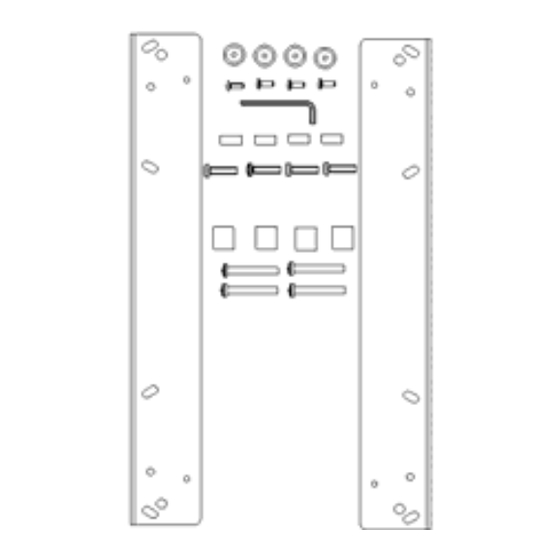
(2) Plasma Static Mount Brackets
(4) 10-24 Button Head Cap Screws
(4) .75 x .26 x .31 Nylon Spacers - White
(4) M6 x 45mm Phillips Head Cap Screws
BEFORE PROCEEDING, READ INSTALLATION INSTRUCTIONS COMPLETELY
CAUTION!
WARNING!
1. Using a 10-24 Button head cap screw inserted from back side of bracket, secure mounting button,
with chamfered hole of mounting button (larger surface) facing bracket, to bracket (four places) (see
Figure 2 and Figure 3).
CHIEF MANUFACTURING INC.
1-800-582-6480 952-894-6280 FAX 952-894-6918
8401 EAGLE CREEK PKWY, STE. 700
SAVAGE, MINNESOTA 55378 USA
PSB-2114
Figure 1
PLASMA DISPLAYS ARE EXTREMELY FRAGILE.
ALL COMPONENTS MUST BE SECURELY FASTENED TO A
STRUCTURAL MEMBER CAPABLE OF SUPPORTING 4
TIMES THE COMBINED WEIGHT OF ALL COMPONENTS
PLUS THE EQUIPMENT BEING MOUNTED. IF IT CANNOT
SUPPORT THIS WEIGHT, THE STRUCTURE MUST BE
REINFORCED.
THE MAXIMUM WEIGHT TO BE INSTALLED ON THE
MOUNT IS 175 POUNDS (79.38 KG).
Figure 2
(4) Mounting Buttons
(4) M6 X 25 mm Phillips Head Cap Screws
(4) 18mm x 8.3mm x 20mm Nylon Spacers - Black
(1) 1/8" Allen Key
Figure 3
2005 Chief Manufacturing
8804-000213 RevC
www.chiefmfg.com
12/05
Advertisement
Table of Contents

Related Manuals for CHIEF PSB-2114


Summary of Contents for CHIEF PSB-2114
- Page 1 (larger surface) facing bracket, to bracket (four places) (see Figure 2 and Figure 3). Figure 2 Figure 3 CHIEF MANUFACTURING INC. 8804-000213 RevC 1-800-582-6480 952-894-6280 FAX 952-894-6918 2005 Chief Manufacturing 8401 EAGLE CREEK PKWY, STE. 700 www.chiefmfg.com...
- Page 2 .313” (white) and 20mm (black) spacers and attach brackets using the longer M6 x 45mm screws. With the aid of another person, lift the display up to the Chief Mount, aligning buttons of mounting brackets with slots in the Chief Mount.
Need help?
Do you have a question about the PSB-2114 and is the answer not in the manual?
Questions and answers