Advertisement
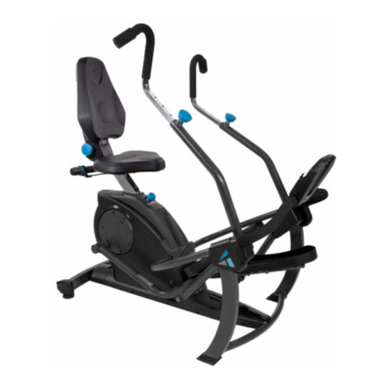
FreeStep
Recumbent Cross Trainer
Assembly Instructions & User Guide
For Zero-Impact Cardio and Muscle Toning Workouts
To download and print the Teeter
FreeStep
instructions, visit the
™
product support page at teeter.com.
* Specifications may vary from this image and are subject
EN
to change without notice. Your actual model may vary.
™
MODEL SE2001
I created Teeter so people could
live healthier, more active lives.
founder & innovator
NEW!
Follow along with
your smartphone
to make assembly
even easier!
Advertisement
Table of Contents

Related Manuals for Teeter FreeStep SE2001


Summary of Contents for Teeter FreeStep SE2001
- Page 1 ™ MODEL SE2001 Recumbent Cross Trainer Assembly Instructions & User Guide For Zero-Impact Cardio and Muscle Toning Workouts To download and print the Teeter I created Teeter so people could FreeStep instructions, visit the ™ product support page at teeter.com.
-
Page 2: Table Of Contents
If you have any questions concerning assembly or if any parts are missing, DO NOT RETURN THE ITEM TO THE STORE OR CONTACT THE RETAILER. Our dedicated customer service experts can help! Contact Teeter Customer Service at 800.847.0143, or via online forms or Live Chat at teeter.com. -
Page 3: Important Safety Instructions
BEFORE YOU BEGIN: Review all steps before beginning assembly and read all precautions before using the Teeter FreeStep ™ Carefully adhere to the Assembly Instructions and User Guide to help ensure safety and product integrity. IMPORTANT SAFETY INSTRUCTIONS ™ READ ALL INSTRUCTIONS BEFORE USING THE TEETER FREESTEP WARNING FAILURE TO FOLLOW INSTRUCTIONS AND WARNINGS COULD RESULT IN SERIOUS INJURY OR DEATH. -
Page 4: Items For Assembly
Items for Assembly Items not shown to scale. Hardware drawings located on the Hardware Kit inserts. ITEM NO. ITEM NAME ITEM NO. ITEM NAME Base Console Front Support Bar SE2101 Base SE1107 Console Front Support Bar HK1047 Step 4a Hardware Kit Rear Stabilizer SE1102 Rear Stabilizer... -
Page 5: Understanding Your Freestep
Understanding Your Teeter FreeStep ™ Before reading further, study the drawing below to familiarize yourself with the important components of your Teeter FreeStep ™ Back Left Right Front Identifying Parts and Components Upper Pedal Arm Base Base Pedal Arms Pedal Arm Joint Cover Sets... -
Page 6: Safety Warning Labels And Product Specifications
This drawing indicates the locations of the warning labels found on your product. If a label is missing, illegible or is removed, contact Teeter Customer Service to request a complimentary replacement label. Note: Image and labels below are not shown in actual size. -
Page 7: Before Beginning Assembly
For step-by-step, 3D interactive instructions, download BILT (a FREE mobile app) to your smartphone to follow along. Simply download the BILT app by scanning the QR code below and then search for your product model (FreeStep SE2001) within the BILT app to get started! Step-by-Step Assembly &... -
Page 8: Assembly Steps
STEP 1 Assemble Rear Stabilizer NOTE: FIGURE 1 • Always hand tighten all the bolts or screws in each step before fully tightening with the wrench or screwdriver. • For reference, the Front, Back, Right and Left of the equipment is labeled on Page 3, Understanding Your FreeStep ™... - Page 9 STEP 2 Assemble Pedals Pedal Installation FIGURE 4 • Locate the Seat Post and raise it to the highest position by pulling up on the Seat Handle (Figure 4). CAUTION Pull Handle Use caution to avoid tipping and when lifting heavy objects. •...
- Page 10 STEP 3 Assemble Seat Seat Installation FIGURE 9 Bolt Spring Washer • Locate the Lower Seat and place it upside-down on a flat surface, such as the edge of a table. Locate the Seat Back Washer Assembly and line it up with the Lower Seat. •...
- Page 11 STEP 4 Assemble Supports Console Front Support Bar Installation FIGURE 12 IMPORTANT: Do not pull or pinch the Speed Sensor Wire during the Console Front Support Bar Installation. • Open the Battery Compartment located on the back of the console. Ensure that the battery contacts and compartment are clean.
- Page 12 STEP 5 Assemble Cover Sets Upper Front Leg Cover Sets Installation FIGURE 17 Phillips Head Screw IMPORTANT: Make sure the Speed Sensor Wire sits under the Left Upper Front Leg Cover Set and is not pinched during installation. TIP: In order to gain better access to the screw holes while assembling the Upper Front Leg Cover Sets, adjust the position of the Pedal Arm Joints by pushing forward or pulling backward on the Handle Support Tubes.
- Page 13 STEP 6 Assemble Handles Handle Installation FIGURE 21 • Loosen the Handle Adjustment Knobs on the right and left Handle Support Tubes by turning the knobs counter-clockwise, then pulling outward (Figure 21). • Locate the Handles, noting Right and Left markings. With the top of the handles pointing outward, insert both Handles into the corresponding Handle Support Tube.
-
Page 15: User Guide
USER GUIDE Leveling FIGURE 24 • Make sure your FreeStep ™ is on a flat, stable surface. Locate the 2 × Leveling Feet as shown. If any of the feet are not resting flat on the ground, rotate them clockwise to lower them until they reach the ground (Figure 24). - Page 16 USER GUIDE Set Seat Height FIGURE 28 CAUTION ALWAYS adjust Seat height first before use to avoid injury to the knees. Proper feet placement and seat height will ensure that your knees never travel over your toes when bent, and that your leg does not lock out in full extension.
- Page 17 USER GUIDE Set Seat Back Position FIGURE 34 • The Seat Back can recline to offer support for the lower back while targeting different muscle groups during your workout. To properly set the Seat Back position, start with the seat in the fully upright position.
- Page 18 USER GUIDE Set Handle Height FIGURE 37 • Loosen the Handle Adjustment Knob by turning it counter-clockwise (Figure 37). • Release the auto-locking mechanism by pulling outward on the spring-loaded Handle Adjustment Knob (Figure 38). • Continue holding the Handle Adjustment Knob outward while pulling or pushing on the handle to adjust the height (Figure 39).
- Page 19 USER GUIDE Set Handle Rotation FIGURE 42 • The handles can be rotated to an Outward Setting or an Inward Setting to target different muscle groups. • To rotate the Handles, loosen the Handle Adjustment Knob by turning it counter-clockwise. Release the auto-locking mechanism by pulling outward on the Handle Adjustment Knob, then rotate the handles as desired (Figure 42).
- Page 20 USER GUIDE Adjust Resistance FIGURE 46 NOTE: The FreeStep™ ships to you set in the highest resistance setting. Dial the Resistance Adjustment Knob to the lowest resistance setting to start out. • To decrease resistance, dial the Resistance Adjustment Knob counter-clockwise (or backward as you are using the equipment).
- Page 21 Handles properly.) Handles properly.) information on how to set the Handles.) FIGURE 48 FIGURE 49 FIGURE 50 For more information about specific FreeStep ™ exercises, visit the Discover Teeter Blog at teeter.com/blog...
-
Page 22: Warranty And Registration
Under no circumstances shall Teeter, or any other party involved in the sale of this product, have any liability for incidental or consequential damage arising from breach of an express or implied warranty on any Teeter product. - Page 24 * Code cannot be combined with any other offer and does not apply to trial. multi-pay options, or previous purchases. U.S. and Foreign Patents Apply. Teeter and Teeter logo are registered trademarks of Teeter. Specifications subject to change without notice.
Need help?
Do you have a question about the FreeStep SE2001 and is the answer not in the manual?
Questions and answers