Table of Contents
Advertisement
Quick Links
ROTARY R
click
™
1. Introduction
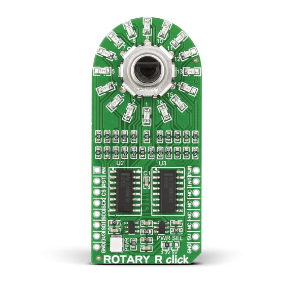
Rotary R click
carries a 15-pulse incremen-
™
tal rotary encoder with detents, surrounded
by a ring of 16 red LEDs. It communicates
with the target board through mikroBUS
SPI lines (CS, SCK, MISO, MOSI), and three
additional lines for outputting the Encoder
info: ENCB OUT, ENCA OUT and SW (in
place of the standard AN, RST and INT pins,
respectively). Rotary R click
™
can be used
with either a 3.3V or 5V power supply.
2. Soldering the headers
Before using your click
™
board, make sure
to solder 1x8 male headers to both left and
right side of the board. Two 1x8 male headers
are included with the board in the package.
2
Turn the board upside down so that
the bottom side is facing you upwards.
Place shorter pins of the header into the
appropriate soldering pads.
™
1
3
Turn the board upward again. Make sure
to align the headers so that they are
perpendicular to the board, then solder the
pins carefully.
3. Plugging the board in
Once you have soldered the headers your
board is ready to be placed into the desired
mikroBUS
socket. Make sure to align the cut
™
in the lower-right part of the board with the
markings on the silkscreen at the mikroBUS
socket. If all the pins are aligned
correctly, push the board all
the way into the socket.
4. Essential features
Rotary R click
™
with its LED ring is a perfect
solution for implementing an input knob into
your design (in contrast to a potentiometer,
a rotary encoder can be spun round
continuously). A single rotation is divided into
15 discrete steps. The encoder outputs A and
B signals (out of phase to each other). The
knob is also a push-button outputted through
the interrupt line. The LED ring are controlled
through the SPI interface.
click
™
BOARD
www.mikroe.com
™
ROTARY R click
™
manual
ver 1.00
0 1 0 0 0 0 0 0 7 7 3 9 9
Advertisement
Table of Contents

Related Manuals for mikroElektronika ROTARY R click


Summary of Contents for mikroElektronika ROTARY R click
- Page 1 If all the pins are aligned ROTARY R click ™ manual ver 1.00 respectively). Rotary R click ™ can be used correctly, push the board all with either a 3.3V or 5V power supply. the way into the socket.
- Page 2 LED07 .com 6. Dimensions 9. Support MikroElektronika assumes no responsibility MikroElektronika offers free tech support mils or liability for any errors or inaccuracies (www.mikroe.com/support) until the end of that may appear in the present document. the product’s lifetime, so if something goes 57.15...
Need help?
Do you have a question about the ROTARY R click and is the answer not in the manual?
Questions and answers