Table of Contents
Advertisement
Quick Links
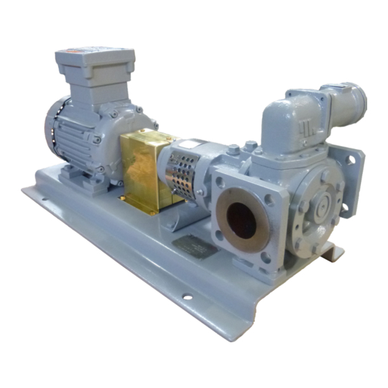
TopGear GS
I N T E R N A L G E A R P U M P S
A . 0 5 0 0 . 5 0 1 – I M - TG G S / 0 5 . 0 1 E N ( 0 3 / 2 0 1 3 )
O R I G I N A L I N S T R U CT I O N S
R E A D A N D U N D E R S TA N D T H I S M A N UA L P R I O R TO O P E R AT I N G O R S E R V I C I N G T H I S P R O D U CT.
I N S T R U CT I O N M A N UA L
Advertisement
Table of Contents

Subscribe to Our Youtube Channel
Related Manuals for Johnson Pump TG GS2-25


Summary of Contents for Johnson Pump TG GS2-25
- Page 1 I N S T R U CT I O N M A N UA L TopGear GS I N T E R N A L G E A R P U M P S O R I G I N A L I N S T R U CT I O N S A .
- Page 2 Machinery Directive 2006/42/EC, Annex IIA Manufacturer SPX Flow Technology Belgium NV Evenbroekveld 2-6 BE-9420 Erpe-Mere Belgium Herewith we declare that TopGear GS-range Gear Pumps Types: TG GS2-25 TG GS3-32 TG GS6-40 TG GS15-50 TG GS23-65 TG GS58-80 TG GS86-100 TG GS185-125...
-
Page 3: Table Of Contents
Contents Introduction ......................7 1.1 General ........................7 1.2 Reception, handling and storage ..............7 1.2.1 Reception ......................7 1.2.2 Handling ......................7 1.2.3 Storage ....................... 7 1.3 Safety ........................8 1.3.1 General ....................... 8 1.3.2 Pump units ......................9 1.3.2.1 Pump unit handling ..................9 1.3.2.2 Installation .......................9 1.3.2.3... - Page 4 3.17 Safety relief valve ..................... 23 3.17.1 Pressure ......................24 3.17.2 Heating ......................24 3.17.3 Safety relief valve – Relative adjustment ...........24 3.17.4 Sectional drawings and part lists ..............26 3.17.4.1 Single safety relief valve ................26 3.17.4.2 Heated spring casing ................27 3.17.4.3 Double safety relief valve ................
- Page 5 4.4 After disassembly ..................... 49 4.5 Anti-friction bearings ..................50 4.5.1 General ......................50 4.5.2 TG GS2-25, TG GS3-32 and TG GS6-40 disassembly .....50 4.5.3 TG GS2-25, TG GS3-32 and TG GS6-40 assembly ......50 4.5.4 TG GS15-50 to TG GS185-125 disassembly ........51 4.5.5...
- Page 6 Sectional drawings and part lists ..............57 5.1 TG GS2-25 to TG GS6-40 ................57 5.1.1 Hydraulic part ....................58 5.1.2 Bearing bracket ....................58 5.1.3 Flange connection options ................58 5.1.4 Jacket .........................59 5.1.5 Single Mechanical seal ..................59 5.2 TG GS15-50 to TG GS185-125 ............... 60 5.2.1...
-
Page 7: Introduction
1.0 Introduction General This instruction manual contains necessary information on the TopGear pumps and must be read carefully before installation, service and maintenance. The manual must be kept easily accessible to the operator. Important! The pump must not be used for other purposes than recommended and quoted for without consulting your local supplier. -
Page 8: Safety
Safety 1.3.1 General Important! The pump must not be used for other purposes than recommended and quoted for without consulting your local supplier. A pump must always be installed and used in accordance with existing national and local sanitary and safety regulations and laws. When ATEX pump/pump unit is supplied, the separate ATEX manual must be considered •... -
Page 9: Pump Units
1.3.2 Pump units 1.3.2.1 Pump unit handling Use an overhead crane, forklift or other suitable lifting device. Secure lifting slings around the If there are lifting rings on both Warning front part of the pump and the the pump and the motor the slings Never lift the pump unit with back part of the motor. -
Page 10: Before Commissioning The Pump Unit
1.3.2.3 Before commissioning the pump unit Read the pump’s operating and safety manual. Make sure that the installation has been correctly carried out according to the relevant pump’s manual. Check the alignment of the pump and motor shafts. The alignment may have been altered during transport, lifting and mounting of the pump unit. -
Page 11: Technical Conventions
Technical conventions Quantity Symbol Unit Dynamic µ mPa.s = cP (Centipoise) viscosity ρ = density Kinematic ν = µ [kg] ρ dm viscosity ν = kinematic viscosity [ mm ] = cSt (Centistokes) Note! In this manual only dynamic viscosity is used. Pressure [bar] ∆p... -
Page 12: Pump Description
2.0 Pump description TopGear/GS pumps are rotary positive displacement pumps with internal gear. They are made of cast iron. TG GS pumps: heating / cooling jackets (steam), several sleeve bearings, gear and shaft materials and mounted relief valve. Type designation The pump properties are encoded in the following type indication, which is to be found on the nameplate. - Page 13 Example 58-80 7. Idler bush and idler materials Idler bush in hardened steel with idler in iron CG Idler bush in carbon with idler in iron Idler bush in bronze with idler in iron HG Idler bush in ceramic with idler in iron Idler bush in hardened steel with idler in steel Idler bush in carbon with idler in steel Idler bush in bronze with idler in steel...
-
Page 14: General Technical Information
3.0 General technical information Pump standard parts Top cover Intermediate casing Pump shaft Bearing bracket Idler pin Rotor Pump cover Idler gear Pump casing Operating principle As the rotor and idler gear unmesh, an underpressure is created and the liquid enters the new created cavities. Liquid is transported in sealed pockets to the discharge side. -
Page 15: Self-Priming Operation
3.2.1 Self-priming operation TopGear pumps are self-priming when sufficient liquid is present in the pump to fill up the clearances and the dead spaces between the teeth. (For self-priming operation see also section 3.18.6.2 Piping). 3.2.2 Safety relief valve – Working principle The positive displacement principle requires the installation of a safety relief valve protecting the pump against overpressure. -
Page 16: Main Characteristics
Main characteristics The pump size is designated by the displacement volume of 100 revolutions expressed in litres (or dm ) but rounded followed by the nominal port diameter expressed in millimetres. ∆p Vs-100 n.max n.mot Q.th Q.th p.test TG GS pump size (mm) (mm) (mm) -
Page 17: Pressure
Pressure Differential pressure or working pressure (p) is the pressure on which the pump normally operates. TopGear GS-line has the maximum differential pressure at 10 bar. TopGear GS-range The hydrostatic test pressure is 1.5 times the differential pressure i.e.: TopGear GS-line has the hydrostatic test pressure at 15 bar. Following figure gives a graphical presentation of the several kinds of pressures. -
Page 18: The Sound Level Of The Pump Unit
3.7.2 The sound level of the pump unit The sound level of the drive (motor, transmission, . . .) must be added to the sound level of the pump itself to determine the total sound level of the pump unit. The sum of several sound levels must be calculated logarithmically. -
Page 19: Internals
3.10 Internals 3.10.1 Bush materials Overview of bush materials and application field Material Code Material Steel Carbon Bronze Ceramic Hard metal if yes to maximum working pressure = 16 bar Hydrodynamical lubrication if no 6 bar (*) 10 bar (*) 6 bar (*) 6 bar (*) 10 bar (*) -
Page 20: Maximum Torque Of Pump Shaft And Rotor Material Combination
3.10.4 Maximum torque of pump shaft and rotor material combination The maximum allowable torque is a constant independent from speed and may not be exceeded to avoid damaging the pump i.e. pump shaft, rotor/shaft fitting and rotor teeth. Mn (nominal torque) in Nm Md (starting torque in Nm N Rotor N Rotor... -
Page 21: Extra Clearances
Code idler x1xx x1xx x2xx x3xx Code pump cover xxx0 xxx1 xxx2 xxx3 assembly TG GS2-25 TG GS3-32 TG GS6-40 TG GS15-50 TG GS23-65 TG GS58-80 TG GS86-100 TG GS185-125 Diametral clearance on pin / idler bearing C1 (µm) C2 (µm) C3 (µm) -
Page 22: Play Between Gear Teeth
3.14 Play between gear teeth TG GS 2-25 3-32 6-40 15-50 23-65 58-80 86-100 185-125 Minimum (µm) Maximum (µm) Play between gear teeth 3.15 Maximum size of solid particles TG GS 2-25 3-32 6-40 15-50 23-65 58-80 86-100 185-125 Size (µm) 3.16 Shaft sealing Mechanical seal according to EN12756 (DIN24960) –... -
Page 23: Safety Relief Valve
V 35 - G 10 H 1. Safety relief valve = V 2. Type indicating = inlet diameter (in mm) Safety relief valve size for TG GS2-25, TG GS3-32, TG GS6-40 Safety relief valve size for TG GS15-50, TG GS23-65 Safety relief valve size for... -
Page 24: Pressure
3.17.1 Pressure Safety relief valves are divided into 3 working pressure classes i.e. 4, 6 and 10 indicating the maximum working pressure for that valve. Each class has a standard set pressure at 1 bar above the indicated maximum working pressure. The set pressure can be set lower on request never higher. Working pressure class Standard set pressure (bar) Working pressure range (bar) - Page 25 Spring ratio – Safety relief valve Spring dimensions TG GS pump size Pressure class bar/mm 25.5 0.26 2-25 3-32 25.5 0.43 6-40 25.5 1.72 37.0 0.21 15-50 37.0 0.21 23-65 36.5 0.81 49.0 0.32 58-80 49.0 0.32 48.6 0.66 49.0 0.16 86-100 48.6...
-
Page 26: Sectional Drawings And Part Lists
3.17.4 Sectional drawings and part lists 3.17.4.1 Single safety relief valve 7400 7240 7030 7330 7040 7180 7100 7100 7110 7300 7310 7320 7050 7170 7010 7150 Single safety relief valve – horizontal 7360 7400 7310 7050 Pos. Description Preventive Overhaul 7180 7010... -
Page 27: Heated Spring Casing
3.17.4.2 Heated spring casing 7041 Pos. Description Preventive Overhaul 7041 Heated spring casing 3.17.4.3 Double safety relief valve 8020 8050 8020 8050 8010 8010 8040 8060 8040 8070 8070 8030 8060 8030 Double safety relief valve – horizontal Double safety relief valve – vertical Pos. -
Page 28: Installation
3.18 Installation 3.18.1 General This manual gives basic instructions which are to be observed during installation of the pump. It is therefore important that this manual is read by the responsible personnel prior to assembly and afterward to be kept available at the installation site. The instructions contain useful and important information allowing the pump/pump unit to be properly installed. -
Page 29: Indoor Installation
3.18.2.4 Indoor installation Locate the pump so that the motor can be vented properly. Prepare the motor for operation according to instructions provided by the motor manufacturer. When flammable or explosive products are pumped, a proper earthing should be provided. The components of the unit should be connected with earthing bridges to reduce the danger arising from static electricity. -
Page 30: Radial Load On Shaft End
3.18.3.2 Radial load on shaft end The shaft end of the pump shaft may be loaded in radial sense with the maximum radial force (Fr). See table. TG GS pump size Fr (N) - max 2-25/3-32 6-40 15-50/23-65 1000 58-80/86-100 2000 185-125 3000... -
Page 31: Double Safety Relief Valve
3.18.5 Double safety relief valve When a double safety relief valve is installed three arrow plates are attached – one on each valve (A and B) indicating the liquid flow direction of each valve (small arrows 2 and 3) and one on the Y-casing (C) indicating the most favourable direction of rotation of the pump (arrow 1). -
Page 32: Piping
3.18.6.2 Piping • Use piping with an equal diameter than the connection ports of the pump and shortest possible. • The pipe diameter has to be calculated in function of the liquid parameters and the installation parameters. If necessary use larger diameters to limit pressure losses. • If the fluid to be pumped is viscous, pressure losses in the suction and discharge lines may increase considerably. Other piping components like valves, elbows, strainers, filters and foot valve also cause pressure losses. -
Page 33: Isolating Valves
3.18.6.3 Isolating valves To allow proper maintenance it is necessary to be able to isolate the pump. Isolation can be done by installing valves in suction and discharge lines. Discharge • These valves must have a cylindrical passage of the same diameter of the piping (full bore). (Gate or ball valves are preferable). -
Page 34: Heating Jackets
3.18.7.2 Heating jackets 1. S-type jackets The S-jackets are designed for use with saturated steam (max 10 bar, 180°C) or with non-dangerous media. They are provided with threaded connections Bl (see chapter 6.0 for the dimensions). The connection can be done by threaded pipes or pipe connections with sealing in the thread (conical thread applying ISO 7/1) or sealed outside the thread by means of flat gaskets (cylindrical thread applying ISO 228/1). -
Page 35: Guidelines For Assembly
3.18.9 Guidelines for assembly When a bare shaft pump is delivered, the assembly with drive is the responsibility of the user. The user also must provide all necessary devices and equipment allowing a safe installation and commissioning of the pump. 3.18.9.1 Transport of pump unit •... -
Page 36: Combustion Engines
Electrical equipment, terminals and components of control systems may still carry live current when at rest. Contact with these may be fatal, resulting in serious injury or cause irreparable material damage. Line Motor U 1 V 1 W 1 U 1 V 1 W 1 U (volt) 230/400 V 400 V... -
Page 37: Instructions For Start-Up
3.19 Instructions for start-up 3.19.1 General The pump can be put into service when all arrangements described in chapter 3.18 Installation have been made. • Prior to commissioning, responsible operators have to be fully informed on proper operation of the pump/pump unit and the safety instructions. This instruction manual must at all times be available to the personnel. -
Page 38: Checklist - Initial Start-Up
3.19.4 Checklist – Initial start-up After thorough servicing or when the pump is to be put into service for the first time (initial start-up) the following checklist must be observed: Supply and discharge line c Suction and discharge pipes are cleaned. c Suction and discharge pipes are checked for leaks. -
Page 39: Start-Up
3.19.5 Start-up When the pump is to be put into service the following checklist and procedure must be observed: c Pump is filled with liquid. c Pump is sufficiently preheated. c Quench media is present. Can it circulate freely? c Suction and discharge valves are fully open. c Start the pump for a short while and check the direction of rotation of the motor. -
Page 40: Trouble Shooting
3.20 Trouble shooting Symptom Cause Remedy No flow Suction lift too high • Reduce difference between Pump not priming pump and suction tank level. • Increase suction pipe diameter. • Reduce length and simplify suction pipe (use as few elbows and other fittings as possible). Also see section 3.18 Installation. - Page 41 Symptom Cause Remedy Not enough capacity Viscosity too low 17 • Increase pump speed. Attention! Do not exceed maximum speed and check NPSHr. • If necessary, install a larger pump. • If pump is heated by means of heating jackets or electrical heating, reduce the heating input.
-
Page 42: Instructions For Re-Using And Disposal
Symptom Cause Remedy Rapid wear of the Viscosity too high 36 • Heat the pump. mechanical seal Bad de-aerating/ dry running 37 • Fill pump with liquid • Check position of relief valve or top cover. Temperature too high 38 • Reduce temperature. •... -
Page 43: Maintenance Instructions
3.21 Maintenance instructions 3.21.1 General This chapter only describes operations that can be performed on-site for normal maintenance. For maintenance and repair requiring a workshop contact your local supplier. • Insufficient, wrong and/or irregular maintenance can lead to malfunctions in the pump, high repair costs and long-term inoperability. Therefore, you should carefully follow the guidelines given in this chapter. -
Page 44: External Cleaning
3.21.2.6 External cleaning • Keep the surface of the pump as clean as possible. This simplifies inspection, the attached markings remain visible and grease nipples are not forgotten. • Make sure cleaning products do not enter the ball bearing space. Cover all parts that must not come into contact with fluids. In case of sealed bearings, cleaning products must not attack rubber gaskets. Never spray the hot parts of a pump with water, as certain components may crack due to the sudden cooling and the fluid being pumped may spray into the environment. -
Page 45: Specific Components
Clogged filter in the discharge line may result in higher discharge pressure. 3.21.3.5 Anti-friction bearings TG GS2-25, TG GS3-32 and TG GS6-40 pumps are equipped with 2RS ball bearings which are grease packed for life. They do not require periodically greasing. -
Page 46: Sleeve Bearings
The standard “multi-purpose” grease (consistent class NLGI-2) is suitable for temperatures up to 120°C. For higher temperatures the standard grease should be replaced by a high temperature grease (consistent class NLGI-3). This grease is, depending on the make, suitable for temperatures up to 150°C or 180°C. -
Page 47: Front Pull-Out
3.21.4 Front pull-out The TG-pumps also have a front pull-out system. To remove liquid residues or to check the idler bearing for wear, the pump cover can be pulled out from the pump housing without disconnecting suction and discharge pipes. See chapters 4.0 Disassembly/Assembly and section 6.6 Weights. -
Page 48: Designation Of Threaded Connections
3.21.7 Designation of threaded connections. To make clear what sealing type of threaded connection is provided we denominate them according to standards ISO 7/1 and ISO 228/1 as follows. 3.21.7.1 Threaded connection Rp (example Rp 1/2) If no flattened sealing face is provided we call the connection Rp accordingly ISO 7/1. This connection has to be sealed in the thread. -
Page 49: Instructions For Assembly And Disassembly
4.0 Instructions for assembly and disassembly General Insufficient or wrong assembly and disassembly can lead to the pump malfunctioning, high repair costs and long-term inoperability. Contact your local supplier for information. Disassembly and assembly may only be carried out by trained personnel. Such personnel should be familiar with the pump and follow the instructions below. -
Page 50: Anti-Friction Bearings
Note! Add a correct grade and the appropriate type of grease. Do not overfill. 4.5.2 TG GS2-25, TG GS3-32 and TG GS6-40 disassembly 1. First disassemble the flexible coupling half using a coupling extractor. 2. Remove key (1570), set screws (1480) and tap bolts (1540). -
Page 51: Tg Gs15-50 To Tg Gs185-125 Disassembly
4.5.4 TG GS15-50 to TG GS185-125 disassembly 1. First disassemble the flexible coupling half with the aid of a coupling extractor. 2. Remove key (1570), set screws (1480), tap bolts (1540) and long screws (1530). 3. Remove the outer bearing cover (1470) and the V-seal (1490). 4. Detach bearing bracket (1400) by loosening the screws (1410). 5. -
Page 52: Mechanical Seal
Mechanical seal Guidelines for assembly and adjustment of the mechanical seal – pump types GS. 4.6.1 General • All personnel responsible for maintenance, inspection and assembly must be adequately qualified. • Use specific instructions coming with the mechanical seal which is to be assembled/adjusted. • The assembling and adjusting of mechanical seals must be performed in a clean workshop. • Use technically appropriate tools that are in good condition. Handle them correctly. 4.6.2 Preparation Check if the mechanical seal to be mounted has the appropriate size and construction and verify if it can be assembled. -
Page 53: Assembly Of The Stationary Seat
• Always replace damaged parts with original parts. • At every disassembly new graphite gaskets must be used. Never re-use gaskets. 4.7.2 TG GS2-25/TG GS3-32/TG GS6-40 Disassembly 1. Remove ball bearing (1440) and bearing bracket (1400) as described in bearing disassembly, section 4.5.2. 2. Remove pump cover (4000) and idler (0600). 3. Remove outer circlips (2230) from the shaft. -
Page 54: Tg Gs15-50/Tg Gs23-65
4.7.3 TG GS15-50/TG GS23-65 Dissasembly 1. Remove ball bearing (1440) and bearing bracket (1400) as described in bearing disassembly, section 4.5.4. 2. Remove pump cover (4000) and idler (0600). 3. Remove bearing cover (2200), outer circlips (2240) from the shaft. 4. -
Page 55: Tg Gs58-80/ Tg Gs86-100/ Tg Gs 185-125
4.7.4 TG GS58-80/ TG GS86-100/ TG GS 185-125 Disassembly 1. Remove ball bearing (1440) and bearing bracket (1400) as described in bearing disassembly, section 4.5.4. 2. Remove pump cover (4000) and idler (0600). 3. Detach bearing cover (2200) by loosening screws (2220) and remove them together with the washers (2290). -
Page 56: Relief Valve
Relief valve • The relief valve may not be disassembled before the spring has been released completely • Before releasing the spring, measure the position of the adjusting bolt, so that the spring afterwards can be adjusted to its original opening pressure 4.8.1 Disassembly • Undo the screws (7310) and the cover (7050). • Measure and record the exact position of the adjusting bolt (7320). (See dimension H). • Loosen nut (7330) and adjusting screw (7320) until the spring (7150) has been completely released. • Remove spring casing (7040) by loosening the screws (7300). •... -
Page 57: Sectional Drawings And Part Lists
When ordering spare parts, please state: 1. Pump type and serial number (see name plate) 2. Position number, quantity and description Example: 1. Pump type: TG GS58-80G2SSG2G1AV Serial number: 2000-101505 2. Pos 0600, 1, Idler + Bush complete TG GS2-25 to 1080 TG GS6-40 0100 1090 1050... -
Page 58: Hydraulic Part
5.1.1 Hydraulic part Pos. Description GS2-25 GS3-32 GS6-40 preventive overhaul 0010 pump casing 0020 Intermediate casing 0040 tap bolt 0100 top cover, complete 0600 idler + bush, complete 0700 rotor + shaft, complete 1030 plug 1040 sealing ring 1050 plug 1060 sealing ring 1080... -
Page 59: Jacket
5.1.4 Jacket 0220 0200 0230 0210 Pos. Description GS2-25 GS3-32 GS6-40 preventive overhaul 0200 jacket cover 0210 tap bolt 0220 gasket 0230 cap head screw 5.1.5 Single Mechanical seal 3010 2240 2230 2210 2250 Pos. Description GS2-25 GS3-32 GS6-40 preventive overhaul 2210 2230... -
Page 60: Tg Gs15-50 To Tg Gs185-125
TG GS15-50 to TG GS185-125 1080 0100 1090 1050 1060 1100 0010 1100 0600 1040 1030 1230 1210 1220 4000 0040 1200 1570 1490 0020 1520 0700 1480 1560 1550 1530 1540 1600 1470 1610 1410 1400 1510 1440 1460 1430 1500 1420... -
Page 61: Hydraulic Part
5.2.1 Hydraulic part Pos. Description GS15-50 GS23-65 GS58-80 GS86-100 GS185-125 preventive overhaul 0010 pump casing 0020 Intermediate casing 0040 tap bolt 0100 top cover complete 0600 idler + bush, complete 0700 rotor + shaft, complete 1030 plug 1040 sealing ring 1050 plug 1060... -
Page 62: Jacket
5.2.3 Jacket 0220 0200 0240 0250 0210 0230 Pos. Description GS15-50 GS23-65 GS58-80 GS86-100 GS185-125 preventive overhaul 0200 jacket cover 0210 tap bolt 0220 gasket 0230 cap head screw 0240 plug 0250 sealing ring 5.2.4 Single mechanical seal 2280 2270 2250 2240 2290... -
Page 63: Dimensional Drawings
6.0 Dimensional drawings Standard pump 6.1.1 TG GS2-25 to TG GS6-40 ma ze 4xøvd ISO/R775 TG GS2-25 TG GS3-32 TG GS6-40 G 1 1/4 G 1 1/2 G 1/4 G 1/4 G 1/4 G 1/4 Rp 3/8 Rp 3/8 5 h9 6 h9 21.5... -
Page 64: Tg Gs15-50 To Tg Gs185-125
6.1.2 TG GS15-50 to TG GS185-125 ma ze 4xøvd ISO/R775 TG GS15-50 TG GS23-65 TG GS58-80 TG GS86-100 TG GS185-125 G 1/4 G 1/4 G 1/2 G 1/2 G 1/2 G 1/2 G 1/2 G 1/2 G 1/2 G 1/2 G 1/4 G 1/4 G 1/4... -
Page 65: Flange Connections
Flange connections 6.2.1 TG GS2-25 to TG GS6-40 øak TG GS2-25 TG GS3-32 TG GS6-40 ac PN16 ac PN20 79.5 98.5 ad PN16 ad PN20 ak PN16 4xd14 4xd18 4xd18 ak PN20 4xd16 4xd16 4xd16 am PN16 am PN20 6.2.2... -
Page 66: Jackets (S) On Pump Cover And Thread Connection
Jackets (S) on pump cover and thread connection 6.3.1 TG GS2-25 to TG GS6-40 2xBl TG GS2-25 TG GS3-32 TG GS6-40 G 1/2 G 3/4 6.3.2 TG GS 15-50 to TG GS185-125 2xBl TG GS15-50 TG GS23-65 TG GS58-80 TG GS86-100... -
Page 67: Safety Relief Valves
Safety relief valves 6.4.1 Single safety relief valve TG GS2-25 TG GS3-32 TG GS6-40 TG GS15-50 TG GS23-65 TG GS pump size 2-25 TG GS58-80 3-32 TG GS86-100 6-40 TG GS185-125 15-50 23-65 58-80 – 86-100 – 185-125 – 6.4.2... -
Page 68: Heated Safety Relief Valve
6.4.3 Heated safety relief valve TG GS15-50 TG GS23-65 TG GS58-80 TG GS86-100 TG GS185-125 TG GS15-50 TG GS23-65 TG GS58-80 TG GS86-100 TG GS185-125 G 1/2 G 1/2 G 1/2 G 1/2 G 1/2 – – – 59.5 98.5 103.5 103.5 –... -
Page 69: Bracket Support
Bracket support 2xvt TG GS2-25 TG GS3-32 TG GS6-40 TG GS15-50 TG GS23-65 TG GS58-80 TG GS86-100 TG GS185-125 Mass Weight TG GS2-25 TG GS3-32 TG GS6-40 Pump (without jackets) Front-Pull out (pump cover+idler) Back-Pull Out (shaft+interm. casing+bracket) Screw on flanges... - Page 72 TopGear GS I N T E R N A L G E A R P U M P S S PX F LOW T E C H N O LO GY B E LG I U M N V Evenbroekveld 2-6 BE-9420 Erpe-Mere, Belgium P: +32 (0)53 60 27 15 F: +32 (0)53 60 27 01...
Need help?
Do you have a question about the TG GS2-25 and is the answer not in the manual?
Questions and answers