
Subscribe to Our Youtube Channel
Related Manuals for Johnson Pump MDR Series


Summary of Contents for Johnson Pump MDR Series
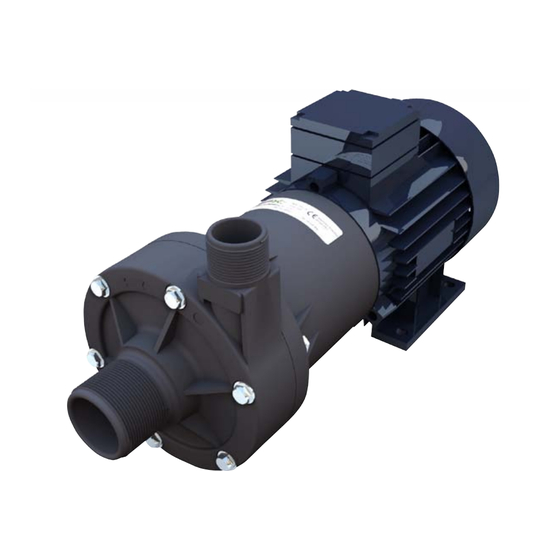
- Page 1 Instruction Manual MDR-series Magnetic Drive Centrifugal Pumps Read and understand this manual prior to operating or servicing this product. MDR/EN (0909)
- Page 2 Declaration of conformity (Directive 98/37/EG, Annex IIA) Manufacturer SPX Process Equipment NL B.V. Dr. A.F. Philipsweg 51, 9403 AD Assen P.O. Box 9, 9400 AA Assen The Netherlands We declare under our sole responsibility that the product: MDR-series Magnetic Drive Centrifugal Pump is in conformity with COUNCIL DIRECTIVE on the approximation of the laws of the Member States relating to Machinery 98/37/EG.
-
Page 3: Table Of Contents
Index Introduction ______________________________________________5 1.1 General ____________________________________________________5 1.2 Reception, handling and storage _______________________________5 1.2.1 Reception __________________________________________________ 5 1.2.2 Handling ___________________________________________________ 5 1.2.3 Storage ____________________________________________________ 6 1.3 Safety _____________________________________________________6 1.4 Type designation ____________________________________________7 1.5 Function and operating principle ______________________________7 1.6 General precautions _________________________________________8 1.7 Standard parts ______________________________________________8 Technical information ______________________________________9 2.1 Material specification ________________________________________9... - Page 4 Spare parts list ___________________________________________18 Trouble shooting chart _____________________________________19 Dimensions and weights ___________________________________21...
-
Page 5: Introduction
1.0 Introduction 1.1 General Johnson magnetic drive centrifugal pumps type MDR are manufactured by SPX Process Equipment, Assen, The Netherlands. This instruction manual contains necessary information on the magnetic drive centrifugal pumps and must be read carefully before installation, service and maintenance. The manual must be kept easily accessible to the operator. -
Page 6: Storage
1.2.3 Storage If the pump is not installed immediately, it must be stored in a dry and cool place. 1.3 Safety Personnel who have a pacemaker should not be allowed to work with the magnetic coupling! The magnetic field is sufficiently strong to affect the operation of a pacemaker. A safe distance is 1 metre! Important! The pump must not be used for other purposes than recommended and quoted for... -
Page 7: Type Designation
• The pump unit must not be exposed to rapid temperature changes of the liquid without prior pre-heating/pre-cooling. Absolutely forbidden to flush a hot pump with cold water. Big temperature changes can cause crack formation or explosion, which in turn can entail severe personal injuries. •... -
Page 8: General Precautions
1.6 General precautions • Do not run dry. If the pump is run without liquid, friction heat will be generated inside the pump which will melt the impeller onto the ceramic shaft and also possibly cause damage to other parts. •... -
Page 9: Technical Information
2.0 Technical information 2.1 Material specification Flange (not exposed to the liquid) Polypropylene filled with glass fibre Magnet housing, impeller, body Polypropylene filled with glass fibre alt Polyvinylidenfluoride with carbon fibre Shaft, wear plates Ceramic/Al Impeller bearings PTFE-Rulon LD O-ring Impeller magnet Ferrite (not exposed to the liquid) -
Page 10: Min Back Pressure
2.3 Min back pressure The MDR-series demands a certain head for good function. Min head = 0.5 m wc or 0.05 bar manometric pressure. If less, install a valve in the discharge Pump pipe to adjust head. 2.4 Min flow required To cool and lubricate the impeller bearing and shaft a certain flow is required through the pump. -
Page 11: Viscosity And Specific Gravity Limits
2.7 Viscosity and specific gravity limits Impeller Max. viscosity cP Specific gravity kg/dm diameter 2.8 Sound level Highest measured sound level for the MDR-pump is 70 dB(A) for pump fitted to standard electric motor. MDR/EN (0909) 1.0... -
Page 12: Capacity
3.0 Capacity 3.1 MDR - 1V (full impeller diameter) Based on water at 20°C (68°F) MDR/EN (0909) 1.0... -
Page 13: Mdr - 1Vd (Reduced Impeller Diameter)
3.2 MDR - 1VD (reduced impeller diameter) Based on water at 20°C (68°F) MDR/EN (0909) 1.0... -
Page 14: Installation And Maintenance
4.0 Installation and maintenance 4.1 General • Anchor the pump properly. • The pump must be provided with lockable circuit breaker to avoid inadvertant starting. • Before any service or maintenance in the pump or system, shut off the power and lock the starting device to prevent inadvertent start. -
Page 15: Start Up
4.3 Start up • Prime pump When operating with lift, prime and work out all air. Note! Pump must not be run without liquid – not even for a short time. When pumping liquids that are easily flammable, no air is allowed in the system. This is absolutely necessary in order to avoid that static electricity is generated in the pump which may cause sevre personal and material damage. -
Page 16: Disassembly And Assembly
4.5 Disassembly and assembly See drawing, section 5.0. Always wear suitable safety clothing. Clean the pump carefully before disassembling. 4.5.1 Disassembly 1. Place the pump vertically with the motor facing downwards and the pump body upwards. 2. Remove the screws (pos 10) and the pump body (pos 8). 3. -
Page 17: Waste Handling/Material Recycling
4.6 Waste handling/material recycling At the products end of life, please dispose of the product according to applicable law. Where applicable, please disassemble the product and recycle the parts material. MDR/EN (0909) 1.0... - Page 18 5.0 Spare parts list 11 12 MDR105/116 Assembling hole Description Material MDR45 MDR75 MDR85 MDR105 MDR116 Flange P2/P3 01-24373-1 58-08299 01-13097-1 58-018376 58-018376 Screw 0.0300.544 0.0300.524 0.0300.523 0.0300.565 0.0300.565 Magnet housing 01-24374-1 58-08301 01-13098-2 58-08334 58-08334 Magnet housing PVDF 01-24405-1 58-08302 01-13113-2 58-08335...
- Page 19 6.0 Trouble shooting chart Problem Possible cause Remedy No flow Air pockets in suction lines Check piping of suction lines and work out all air Lack of prime (when suc- Prime again tion head is negative) Air pockets inside the Work out all air pump Insufficient suction head...
- Page 20 Problem Possible cause Remedy Leakage from pump Loose pump body screws Tighten screws body Wrongly installed O-ring Replace O-ring Damaged O-ring Replace O-ring Make sure that the material is resistant to the media Shaft break Dry running, thermal-shock, Replace shaft running against closed Make sure that the material valve, shock at...
- Page 21 7.0 Dimensions and weights Dimensions in mm Weight, kg Compl Head Male Male Ø pump kit* MDR45P-1V/-1VD BSP1" BSP1/2" MDR75P-1V/-1VD BSP1.1/4" BSP3/4" MDR85P-1V/-1VD BSP1.1/2" BSP1" 10,3 MDR105P-1V/-1VD 58,5 BSP2" BSP1.1/4" 23,6 MDR116P-1V/-1VD 58,5 BSP2" BSP1.1/4" 26,6 * without motor M (2x) Coupling towards motor shaft ø...
Need help?
Do you have a question about the MDR Series and is the answer not in the manual?
Questions and answers