Advertisement
I N S T R U CT I O N M A N UA L
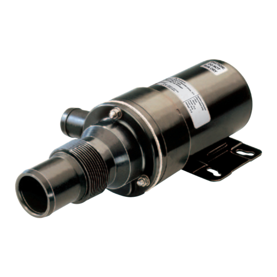
Macerator
TA 3 P - 10
O R I G I N A L I N S T R U CT I O N S / T R A N S L AT I O N O F O R I G I N A L I N S T R U CT I O N S
I B - 4 01 R 0 3 ( 0 3 / 2 016 )
R E A D A N D U N D E R S TA N D T H I S M A N UA L P R I O R TO O P E R AT I N G O R S E R V I C I N G T H I S
P R O D U CT
Advertisement
Table of Contents

Related Manuals for Johnson Pump SPXFLOW Macerator TA3P-10


Summary of Contents for Johnson Pump SPXFLOW Macerator TA3P-10
- Page 1 I N S T R U CT I O N M A N UA L Macerator TA 3 P - 10 O R I G I N A L I N S T R U CT I O N S / T R A N S L AT I O N O F O R I G I N A L I N S T R U CT I O N S I B - 4 01 R 0 3 ( 0 3 / 2 016 ) R E A D A N D U N D E R S TA N D T H I S M A N UA L P R I O R TO O P E R AT I N G O R S E R V I C I N G T H I S P R O D U CT...
-
Page 2: Macerator Pump
Pump may be mounted in any position with-out recreational vehicles loss of efficiency; however, it is suggested that The SPX FLOW Johnson Pump macerator pump the pump head be down if vertical mounting is TA3P10-19 takes care of toilet waste. -
Page 3: Waste Handling Material Recycling
> English Service instructions Wiring scheme (see page 18- 19) (see page 16-17) Wiring table Disassembly (based on 3 % voltage drop) 1. Remove nut, washer and housing. 2. Remove cutter. Use a 7 mm open-ended Wire Max wire length* spanner to hold shaft behind cutter. - Page 4 Pressure and capacity data (based on water at 20°C/68ºF) Ampere draw Bar kPa l/min USGPM 12 V 24 V 0,2 20 10,0 13 A 0,4 40 13,4 34 14 A 0,6 60 20,1 30 14 A 0,8 80 26,8 28 15 A 1,0 100 33,5 22 15 A...
- Page 5 Meassure to outlet 111,7 68,3 178,2 Ø 5 (4x) (12,5) 12,5 SECTION A-A...
- Page 6 Parts list Pos Nos Description 01-24466-01 Motor 12V 01-24466-02 Motor 24V 01-35275-2 Body 01-35719-1 Mill housing 09-1052S-9 Impeller 37-3206221 Wear plate 37-3206217 Gasket 05-29-135 Lip seal 05-06-583 O-ring 37-3206218 Cutter 05-04-577 Screw 05-05-511 05-01-520 Washer 05-04-643 Screw 05-17-535 Fuse 15A, 12V 05-17-550 Fuse 10A, 24V 09-45595...
- Page 7 Wiring scheme Terminal fuse Switch Fuse (overload protection) Pump Max 0,2 m C Black Green/yellow Electrical installation must be according to ISO 10133. Other electrical devices, eg switch, circuit breaker, must be installed between the pump and the positive (+) lead on the battery (on the red wire).
Need help?
Do you have a question about the SPXFLOW Macerator TA3P-10 and is the answer not in the manual?
Questions and answers