Table of Contents
Advertisement
Quick Links
Advertisement
Table of Contents

Subscribe to Our Youtube Channel
Related Manuals for Ubiquiti UniFi LED ULED-AT


Summary of Contents for Ubiquiti UniFi LED ULED-AT
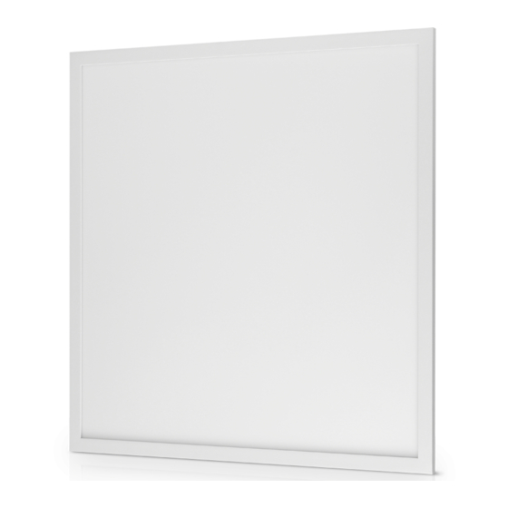
- Page 1 Network-Managed LED Panel Powered by PoE+ Model: ULED-AT...
-
Page 2: Package Contents
Introduction Thank you for purchasing the Ubiquiti Networks® UniFi® LED Panel. This Quick Start Guide is designed to guide you through installation and includes warranty terms. Package Contents Network-Managed LED Panel Powered by PoE+ Model: ULED-AT UniFi LED Panel Quick Start Guide System Requirements •... -
Page 3: Network Topology Requirements
Network Topology Requirements There are three ways to control the UniFi LED Panel: UniFi Dimmer Switch Users in the immediate vicinity control the UniFi LED Panel using the UniFi Dimmer Switch. UniFi LED App over Layer 2 Network A local user runs the app to connect to a UniFi AP on the same Layer 2 network as the UniFi LED Panel. - Page 4 Network topology requirements are as follows: • DHCP-enabled network (for the UniFi LED Panel to obtain an IP address) • For UniFi Dimmer Switch only: A UniFi Dimmer Switch connected to the same Layer 2 network as the UniFi LED Panel •...
-
Page 5: Hardware Overview
Hardware Overview Status LED LED Color Status Flashing White Initializing. Steady White System ready. Steady Blue Adopted by LED Controller. Alternating Firmware upgrade is taking place. White/Blue... - Page 6 ULED-AT-XXXXXX Reset Sticker PoE+ Port PoE+ The PoE+ port is a 10/100 Ethernet port used to connect the power and should be connected to the LAN. Power is provided by a UniFi Switch with 802.3at PoE+. Note: The PoE+ port requires 25W of power, which can be supplied by an 802.3at-compliant UniFi Switch.
-
Page 7: Installation
Installation To install and configure the UniFi LED Panel: 1. Connect one end of an Ethernet cable to the PoE+ port on the back of the UniFi LED Panel. 2. Connect the other end of the cable to an 802.3at-compliant switch port that can provide 25W PoE+. - Page 8 Configuring the UniFi LED Panel Follow the instructions for the software you wish to use: UniFi LED App 1. Install the UniFi LED app on your smartphone or mobile device. The app is available from the App Store® or Google Play Store.
- Page 9 UniFi LED Controller Software 1. Install the latest version of the UniFi LED Controller software on a computer on the same Layer 2 network as the UniFi LED Panel: • Ubuntu users Download the software from www.ubnt.com/download/unifi-led UAS users • Install the software using the UAS management console.
-
Page 10: Quick Setup
Quick Setup This section describes the Quick Setup procedure for installations with large numbers of UniFi LED Panels and Dimmer Switches. The Quick Setup requires using the UniFi LED app along with a QR Code Log that you create. Each UniFi LED Panel or Dimmer Switch has a removable MAC Sticker on its reverse side;... - Page 11 Install the LED Panels and Dimmer Switches For each UniFi LED Panel or Dimmer Switch: 1. Remove the MAC Sticker from the back of the device by carefully peeling back and pulling the blue tab. 2. Place the sticker on the QR Code Log sheet that matches the device’s location.
- Page 12 Scan the QR Codes 1. On your mobile device, open the UniFi LED app. 2. Go to the More screen. Tap Quick Setup. 3. Follow the instructions as the UniFi LED app guides you through the process of adding devices by scanning the QR codes on the QR Code Log sheet(s).
-
Page 13: Specifications
Specifications ULED-AT Dimensions 602 x 602 x 56.7 mm (23.7 x 23.7 x 2.23") Weight 4.5 kg (9.92 lb) Networking Interface 10/100 Mbps Ethernet Port Connectivity Bluetooth 4.1 Buttons Reset LEDs Status Power Method 802.3at PoE+ Supported Voltage Range Standard PoE+ 42.5-57.0V Max. -
Page 14: Safety Notices
Safety Notices Read, follow, and keep these instructions. Heed all warnings. Only use attachments/accessories specified by the manufacturer. WARNING: Do not use this product in a location that can be submerged by water. WARNING: Avoid using this product during an electrical storm. - Page 15 Compliance Changes or modifications not expressly approved by the party responsible for compliance could void the user’s authority to operate the equipment. This device complies with Part 15 of the FCC Rules. Operation is subject to the following two conditions. This device may not cause harmful interference, and This device must accept any interference received, including interference that may cause undesired operation.
-
Page 16: Online Resources
New York, NY 10017 ©2017-2019 Ubiquiti Networks, Inc. All rights reserved. Ubiquiti, Ubiquiti Networks, the Ubiquiti U logo, the Ubiquiti beam logo, and UniFi are trademarks or registered trademarks of Ubiquiti Networks, Inc. in the United States and in other countries. Apple and the Apple logo are trademarks of Apple Inc., registered in the U.S.
Need help?
Do you have a question about the UniFi LED ULED-AT and is the answer not in the manual?
Questions and answers