Table of Contents
Advertisement
Quick Links
a
Using the Avid Nitris
Important Information
®
Avid
recommends that you read all the information in these installation instructions
thoroughly before connecting or using your new hardware and software.
This document explains how to use and to connect cables and devices to the Avid Nitris
Digital Nonlinear Accelerator (DNA) and how to connect specific devices to an
Avid-supported system to which the Avid Nitris is connected. Avid-supported systems for
your Avid Nitris can change at any time.
n
Make sure to look at the ReadMe file that installs with the application. It contains important
information that is used in conjunction with the information presented in this document.
Contents
If You Need Help . . . . . . . . . . . . . . . . . . . . . . . . . . . . . . . . . . . . . . . . . . . . . . . . . . . . . . . . . . 3
Symbols and Conventions. . . . . . . . . . . . . . . . . . . . . . . . . . . . . . . . . . . . . . . . . . . . . . . . . . . 4
Overview . . . . . . . . . . . . . . . . . . . . . . . . . . . . . . . . . . . . . . . . . . . . . . . . . . . . . . . . . . . . . . . . 4
Site Planning . . . . . . . . . . . . . . . . . . . . . . . . . . . . . . . . . . . . . . . . . . . . . . . . . . . . . . . . . . . . . 5
Environmental Requirements . . . . . . . . . . . . . . . . . . . . . . . . . . . . . . . . . . . . . . . . . . . . . 6
Electrical Requirements . . . . . . . . . . . . . . . . . . . . . . . . . . . . . . . . . . . . . . . . . . . . . . . . . 6
Rack Mounting the Avid Nitris Enclosure . . . . . . . . . . . . . . . . . . . . . . . . . . . . . . . . . . . . . . . 7
Equipment Environmental and Safety Guidelines . . . . . . . . . . . . . . . . . . . . . . . . . . . . . 8
Installing the Avid Nitris in a Rack . . . . . . . . . . . . . . . . . . . . . . . . . . . . . . . . . . . . . . . . . 8
Positioning the Avid Nitris in the Rack . . . . . . . . . . . . . . . . . . . . . . . . . . . . . . . . . . . 8
Securing the Avid Nitris in a Rack . . . . . . . . . . . . . . . . . . . . . . . . . . . . . . . . . . . . . 10
Avid Nitris Front Indicators and Rear Connectors . . . . . . . . . . . . . . . . . . . . . . . . . . . . . . . . 12
Front Panel . . . . . . . . . . . . . . . . . . . . . . . . . . . . . . . . . . . . . . . . . . . . . . . . . . . . . . . . . . 12
™
Advertisement
Table of Contents

Related Manuals for Avid Technology Nitris


Summary of Contents for Avid Technology Nitris
-
Page 1: Table Of Contents
Avid Nitris Front Indicators and Rear Connectors ....... . 12... - Page 2 Avid Nitris Base Board Connection ........
-
Page 3: If You Need Help
Technical Support Information ..........56 If You Need Help If you are having trouble using Avid Nitris: 1. Retry the action, carefully following the instructions given for that task. It is especially important to check each step of your workflow. -
Page 4: Symbols And Conventions
You then edit the media on the Avid editing system and send it back to the Avid Nitris. You can change the format and resolution as needed for video and audio output. -
Page 5: Site Planning
Avid Nitris and the other end of the cables have eight separate XLR connectors supporting eight channels of audio. For more information, see “Connecting Audio” on page The Avid Nitris is shipped with the Using the Avid Nitris CD-ROM that includes this online document. Site Planning When preparing your site, you must consider the environmental, electrical, and space requirements for your Avid Nitris workstation, as well as any additional equipment. -
Page 6: Environmental Requirements
Uses an uninterruptible power supply (UPS) to protect your workstation from sudden power surges or losses, and to save you from the resulting loss of work. Plug only your Avid Nitris equipment into the power strip. Do not plug in coffee makers, radios, lights, or other such devices. -
Page 7: Rack Mounting The Avid Nitris Enclosure
This section provides the information for mounting the Avid Nitris in a 19-inch (483-mm) National Electrical Manufacturers Association (NEMA) or Electronics Industries Association (EIA) rack. Avid recommends that you mount your Avid Nitris in a rack before you connect any cables. -
Page 8: Equipment Environmental And Safety Guidelines
The Avid Nitris is designed for 19-inch (483-mm) rack enclosures and requires three EIA rack units (3U), or 5 ¼ inches (133.4 mm) of rack space. The Avid Nitris is shipped with rack-nut clips for those rack enclosures that do not have threaded holes. Rack-nut clips are clipped in the holes of the rack that are used to secure the rack components in place. - Page 9 To position the Avid Nitris in the rack enclosure and attach the rack-nut clips: 1. Select the lowest position in the rack where you can mount the Avid Nitris. Position the Avid Nitris so the bottom is at the baseline of a U-alignment position.
-
Page 10: Securing The Avid Nitris In A Rack
2. From the inside of the enclosure rail, slide the rack-nut clip over each hole you want to use. Each front support rail needs 2 rack-nut clips for the front of the Avid Nitris. Attaching Rack-Nut Clips onto the Rack Enclosure... - Page 11 Rack Mounting the Avid Nitris Enclosure To secure the Avid Nitris into the rack. 1. From the front of the rack, position the Avid Nitris so that it is flush against the front mounting rails. Installing an Avid Nitris Front mounting rail Screws 2.
-
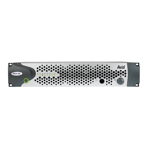
Page 12: Avid Nitris Front Indicators And Rear Connectors
Avid Nitris Front Indicators and Rear Connectors The Avid Nitris provides the high definition and standard definition input and output for your Avid editing system. The front panel of the Avid Nitris has several status LEDs, audio meters, and a power button. - Page 13 Lit when the application is set to capture an analog video input and the signal is present. The ANA and SD LEDs are always lit when the system is capturing analog SD video. Avid Nitris does not capture analog HD so the ANA does not light during an HD capture.
-
Page 14: Rear Panel
Avid Nitris to the system using the digital interlink cable. Digital interlink cable transfers video signal data between the workstation’s Avid Nitris Base board and the Avid Nitris. The SD Video I/O board also provides a connection for syncing equipment to the Avid Nitris. -
Page 15: Hd Video I/O Board Connectors
Avid Nitris Front Indicators and Rear Connectors HD Video I/O Board Connectors The following figure shows the connections on the HD video I/O board. The following table describes the function of each connector. You select which inputs to use from the Capture tool when inputting. -
Page 16: Eight-Channel Audio I/O Board Connectors
HD Video I/O Board Identifiers (Continued) Number Label Function HD COMPONENT OUT, PR HD analog component video output, PR color difference signal, BNC connector; connects to analog video input of a monitor or waveform /vectorscope. HD TRILEVEL SYNC High-definition video reference input for tri-level sync. Eight-Channel Audio I/O Board Connectors The following figure shows the connections on the eight-channel audio I/O board. - Page 17 Avid Nitris Front Indicators and Rear Connectors Eight-Channel Audio I/O Board Identifiers (Continued) Number Label Function S/PDIF IN S/PDIF digital input, white phono (RCA) jack. S/PDIF OUT S/PDIF digital output, red phono (RCA) jack. AES/EBU IN/OUT Channels 1 - 8 AES/EBU digital input and output, 25-pin DSUB-connector;...
-
Page 18: Sd Video I/O Board Connectors
SD Video I/O Board Connectors The following figure shows the connections on the SD video I/O board. The following table describes the function of each connector. You select which inputs to use from the Capture tool when inputting. SD Video I/O Board Connectors ANALOG IN ANALOG OUT OUT 1... - Page 19 Digital Audio Extraction (DAE) interface, 9-pin DSUB connector. DAE is currently not supported in the Avid Nitris. SYSTEM Audio, video, and communication I/O connector from the Avid Nitris system. LTC IN Longitudinal timecode input, female connector. Can be used in place of 9-pin deck control when deck control is not required.
-
Page 20: Workstation Overview
HP Workstation xw8200 Slot Configuration and Connections Avid has qualified the xw8200 workstation with the NVIDIA graphics board to be used with the Avid Nitris. The following figure identifies the slots and connections on the rear of the xw8200 workstation. - Page 21 Avid Nitris Base board Processes video capture, playback I/O, and hardware 133 MHz, 3.3 V) effects for the Avid Nitris and routes video to the NVIDIA graphics board. The Nitris Base board must run at 100 MHz. The board is installed into the PCI-X 133 MHz bus slot but Avid sets this PCI-X slot to run at 100 MHz in the BIOS.
-
Page 22: Avid Nitris Base Board Connection
Avid Nitris Base Board Connection Avid Nitris Base board label Digital interlink cable connector There is a similar connector on the Nitris Codec board which is currently not used. Make sure you connect the digital interlink cable to the board labeled “Nitris Base.”... -
Page 23: Connecting The Avid Nitris
To connect the Avid Nitris to the workstation: 1. Make sure that the power on the Avid Nitris is Off. 2. Attach the power cord to the power connector at the back of the Avid Nitris and plug it into a power outlet. -
Page 24: Connecting The Keyboard And Mouse
Connecting the Keyboard and Mouse The keyboard and mouse come with attached cables for connecting them to the back panel of your workstation. The following figure shows the keyboard and mouse connections on a deskside workstation. Connecting the Keyboard and Mouse Keyboard Mouse To connect the keyboard and mouse:... -
Page 25: Connecting The Monitors
Workstation Overview Connecting the Monitors Your workstation comes with two monitors for Avid Nitris. You can purchase either standard high-resolution flat-panel monitors or VGA monitors. The monitors connect to the NVIDIA graphics board (see the following figure). The NVIDIA graphics board is located in the PCI Express slot 2. -
Page 26: Connecting The Application Key
USB port Connecting the SCSI Local Storage Systems Avid Nitris editing systems support the Avid MediaDock Ultra320 as a local SCSI storage system. Local storage connects to the two SCSI channels at the rear of the workstation and must be striped to provide the needed throughput. -
Page 27: Avid Mediadock Ultra320
MediaDock Ultra320 can be configured in either a single-bus or a dual-bus configuration. The Avid Nitris application requires a minimum of 6 SCSI drives in the Avid MediaDock Ultra320. At this time Avid Nitris supports the following two configurations of the Avid MediaDock Ultra320: •... - Page 28 When using two Avid MediaDock Ultra320 enclosures in single-bus mode, create a two-way stripe across both SCSI bus channels using 24 SCSI drives (12 in each enclosure). Storage Configuration with MediaDock Ultra320 Chassis in Single-Bus Mode Very high-density cable interconnect (VHDCI) connectors...
-
Page 29: Formatting And Striping Media Drives
Connecting the SCSI Local Storage Systems When using one Avid MediaDock Ultra320 enclosure, configure the MediaDock Ultra320 to dual-bus mode and create a two-way stripe across both SCSI bus channels using 12 SCSI drives (6 on each bus). If you have less than 12 SCSI drives, divide the number of drives you have evenly between the two busses. -
Page 30: Avid Unity Environment
Avid Unity media networks are shared storage and networking solutions for sharing media between multiple workstations. Depending on which Avid Unity environment you have, a specific media network board is installed in PCI slot 5 of your Avid Nitris workstation. •... -
Page 31: Reference Signal
To make sure the configuration you are using is properly synced, read the documentation that ships with each of your video devices. Avid Symphony Nitris requires that the VTR and the Avid Nitris hardware be genlocked to the same timing source when capturing or outputting a digital cut. -
Page 32: Tri-Level Sync
You must use a synchronization signal to synchronize your VTR and the Nitris video subsystem for all the HD formats supported by Avid Nitris. Some HD formats can use a black burst sync. For more information see “Selecting Sync for HD Formats” in the Help. -
Page 33: Connecting Video
1. Connect the HD In on the Avid Nitris to the HD Out on the VTR. 2. Connect one of the HD Out, on the Avid Nitris to the HD In on the VTR. 3. Connect the other HD Out on the Avid Nitris to the HD In on the video monitor. -
Page 34: Connecting A Video Deck - Component Signal
7. Plug one end of a BNC sync cable into the Avid Nitris SD sync or HD tri-level input and the other into the reference signal. Connecting Video Devices RS-232 cable serial port RS-232 to RS-422 adapter RS-422 cable Digital interlink cable... - Page 35 Connect the BNC attached to the blue wire to the component output connector labeled B-Y. 4. Locate another component video cable and attach it to the Avid Nitris outputs as follows: a. Connect the BNC attached to the green wire to the component output connector labeled Y.
-
Page 36: Connecting A Video Deck - Composite Signal
To connect a deck using composite signals: 1. Locate one composite video cable. 2. Attach one end of the cable to the Avid Nitris Composite output connector on the SD video I/O board. Connecting a Video Deck — Composite Signal... -
Page 37: Connecting A Video Deck - Serial Digital Signal
To connect a deck using serial digital signals: 1. Locate one serial digital cable. 2. Attach one end of the cable to the SDI IN on the Avid Nitris SD video I/O board or HD SDI IN on the HD video I/O board. -
Page 38: Connecting A Video Deck - S-Video Signal
A video deck with S-Video inputs and outputs To connect a deck using S-Video signals: 1. Locate one S-Video cable. 2. Attach one end of the cable to the Avid Nitris S-Video IN connector on the SD video I/O board. HD SDI IN... -
Page 39: Controlling A Video Deck
Connecting Audio and Video Equipment Controlling a Video Deck Avid editing systems provide video deck control through a serial control connector on most decks. You can control a single deck by using an RS-232 to RS-422 serial adapter. The adapter converts an RS-232 signal to an RS-422 signal to control a VTR from your Avid editing workstation. -
Page 40: Connecting Audio
Connecting Audio Avid provides three audio cable harnesses with the Avid Nitris. Each cable is color coded and labeled for Avid Nitris connections. The cables are identified as follow: • Line In Balanced (blue, eight XLR female) • Line Out Balanced (red, eight XLR male) •... - Page 41 To connect your audio equipment: 1. Make sure that the Avid Nitris power is off. 2. Connect the audio output ports on the Avid Nitris to the input ports on the VTR or audio device. 3. Connect the audio input ports on the Avid Nitris to the output ports on the VTR or audio device.
-
Page 42: Connecting A Client Monitor
Most video decks provide a video output connector. You can connect a monitor to the deck to see the video sent to the Avid Nitris or the video the Avid Nitris sends to the deck. See the documentation that came with your video deck for more information. -
Page 43: Connecting Serial And Midi Port Devices
Connecting Serial and MIDI Port Devices • 1080p/25 (marginal - PsF) • 720p/23.976 • 720p/59.94 You can also use the 15-pin D-sub VGA connector with a BNC adapter cable in Y, Pb, Pr output mode for an extra analog color difference output in addition to the primary on board Y, Pb, Pr BNC outputs. -
Page 44: Connecting The Usb Devices To The Usb Hub
USB Hub DC connector AC power adapter USB hub USB cable USB ports Device connection On/Off switch USB connector Power connection Device connector To connect the USB hub: 1. Connect the power adapter to the USB hub: a. Plug the dc connector of the ac power adapter into the USB hub power connection. b. -
Page 45: Connecting The Usb-To-Serial Adapter
The MIDISPORT 2x2 by M-AUDIO has been tested with the Avid Symphony Nitris system. You need a USB cable that connects to a USB port on the system. Before you use the USB-to-MIDI converter, you must install the latest revision of the driver. -
Page 46: Connecting Jl Cooper Fader Controllers
To connect the USB-to-MIDI converter to a port on the USB hub: 1. Locate the MIDI converter USB cable. 2. Connect the device connector of the USB cable to the device connector on the USB-to-MIDI converter. 3. Connect the other end of the USB cable to a USB port on the computer or USB hub (see “USB Hub”... - Page 47 Connecting Serial and MIDI Port Devices You can use the In A and Out A connector pair or the In B and Out B connector pair on the rear of the USB-to-MIDI converter. Whichever pair you use, select the corresponding port when you configure the device using the Controller Settings dialog box in the Avid editing application.
-
Page 48: Connecting The Yamaha 01V/96 Mixer
JL Cooper FaderMaster Pro Fader Controller Cabling MIDI cable MIDI IN Power 9VDC MIDI In MIDI Out Switch In Switch Out Out A In B Out B USB-to-MIDI MIDI OUT Out A converter (rear) MIDI cable to In A (see “USB-to-MIDI Converter Front Panel”... - Page 49 Connecting Serial and MIDI Port Devices You can use the In A and Out A connector pair or the In B and Out B connector pair on the rear of the USB-to-MIDI converter. Whichever pair you use, select the corresponding port when you configure the device using the Controller Settings dialog box in the Avid editing application.
-
Page 50: Installing And Removing The Avid Fan
Installing and Removing the Avid Fan The documentation that ships with the HP Workstation explains how to install optional equipment. However, Avid requires an extra fan in the HP Workstation for cooling the Avid board set. The following procedure describe how to install the fan Avid has added to the HP Workstation. - Page 51 Installing and Removing the Avid Fan 5. Lower the other end of the fan, pushing it down and towards the rear of the system until you have a pressure fit, carefully watching for the cables on the side of the system. Lowering Fan Into Place Cables 6.
-
Page 52: Regulatory And Safety Notices
Regulatory and Safety Notices The following sections explain the regulatory and safety notices for the Avid Nitris. Warnings and Cautions Never install equipment if it appears damaged. Disconnect the power cord before servicing unit. Only perform the services explicitly described in this document. For services or procedures not outlined in this document, speak with authorized Avid service personnel. -
Page 53: European Union Notice
Conformity is CISPR 22:1997 / EN55022:1994 + A1:1995 + A2:1997 Class A Declared: EN55024:1998/EN61000 — 3-2, 4-2, 4-3, 4-4, 4-5, 4-6, 4-11 Manufacturer’s Name: Avid Technology, Inc. 1925 Andover Street Tewksbury, MA 01876, USA European Contact: Nearest Avid Sales and Service Office or Avid Technology International B.V. - Page 54 Product Name: Products for the Windows NT, Windows 2000, or Windows XP Operating System: Avid Adrenaline DNA, Avid DS Nitris DNA, Avid Equinox Break-Out-Box, Avid|DS, Avid Xpress, Avid Xpress DV, Film Composer, Media Composer, MediaDock, MediaDock 2+, MediaDrive, MediaRAID, MEDIArray,...
-
Page 55: Disposal Of Waste Equipment By Users In The European Union
Disposal of Waste Equipment by Users in the European Union (1) Products for the Windows NT, Windows 2000, or Windows XP Operating System: products were tested in a typical Avid Adrenaline DNA, Avid DS Nitris DNA, Avid Equinox Break-Out-Box, Avid|DS, Avid Xpress, Avid Xpress DV, Film Composer, Media Composer,... -
Page 56: Australia And New Zealand Emc Regulations
Australia and New Zealand EMC Regulations N1709 John Kells, Australian Operations Manager Avid Technology (Australia) Unit B 5 Skyline Place French Forest NSW 2086 Australia Phone: 61-2-8977-4800 Taiwan EMC Regulations Taiwan EMC Regulations BSMI Class A EMC Warning Technical Support Information Most products feature a number of coverage options. - Page 57 Copyright and Disclaimer Copyright and Disclaimer Product specifications are subject to change without notice and do not represent a commitment on the part of Avid Technology, Inc. The software described in this document is furnished under a license agreement. You can obtain a copy of that license by visiting Avid's Web site at www.avid.com.
Need help?
Do you have a question about the Nitris and is the answer not in the manual?
Questions and answers