
Related Manuals for Lincoln P502


Summary of Contents for Lincoln P502
- Page 1 Installation instructions following machinery directive 2006/42/EC Piston pump P502 951-171-009-EN Version 11 2016/06/29...
- Page 2 Designation: Pump to supply lubricant within a centralized lubrication system Type: P502 Part number: 658-XXXXX-X Year of construction: See type identification plate complies with the following basic safety and health requirements of the EC machinery directive 2006/42/EC at the time when first being launched in the market.
- Page 3 Legal disclosure Legal disclosure Warranty Manufacturer The instructions following machinery direc- The instructions do not contain any infor- SKF Lubrication Systems Germany GmbH tive 2006/42/EC are part of the described mation on the warranty. This can be found Walldorf Facilities product and must be kept at an accessible in our general terms and conditions.
-
Page 4: Table Of Contents
Table of contents Table of contents 1. Safety instructions ....................8 Possible settings of lube and pause times of pumps with control pcb ..27 General safety instructions ................8 Tightening torques ..................28 General behaviour when handling the product ..........8 Lubricant requirement for priming of an empty pump ....... - Page 5 Table of contents Inspections prior to initial start-up ..............45 11.2 Pressure reducing valve .................. 58 Triggering and additional lubrication cycle ........... 45 11.3 Adaptor with lubrication fitting ..............58 11.4 Spare parts kit for replacement of the reservoir .......... 59 8.
- Page 6 Explanation of symbols and signs Explanation of symbols and signs Please observe the warning and safety You will find these symbols, which warn of Symbols notes and exercise particular caution in specific dangers to persons, material assets, Symbol Meaning these cases. or the environment, next to all safety in- Inform also other users accordingly.
- Page 7 Explanation of symbols and signs Abbreviations and conversion factors Abbreviations regarding Ounce approx. approx. pounds per square inch °C degrees Celsius relative humidity cu.in cubic inch second dB (A) Sound pressure level sq.in. square inch i.e. that is etc. et cetera etc.
-
Page 8: Safety Instructions
1. Safety instructions 1. Safety instructions 1.2 General behaviour when handling the 1.1 General safety instructions product The owner must ensure that safety in- ○ The product may be used only in aware- formation has been read by any persons ○... -
Page 9: Qualified Technical Personnel
1. Safety instructions 1.3 Qualiied technical personnel tries outside the scope of DIN VDE 0105 or Only qualified technical personnel may IEC 364. install, operate, maintain, and repair the The core principles of these country-specific products described in this document. Quali- qualification requirements for technical fied technical personnel are persons who personnel cannot be below those of the two have been trained, assigned, and instructed... -
Page 10: Electric Current Hazard
1. Safety instructions 1.5 System pressure hazard 1.4 Electric current hazard 1.7 Operation The following must be observed during CAUTION WARNING commissioning and operation. ○ All information within this manual and Electric shock System pressure the information within the referenced Working on products not discon- The product is pressurized during documents. -
Page 11: Assembly, Maintenance, Malfunctions, Shutdown, Disposal
1. Safety instructions 1.9 Assembly, maintenance, malfunctions, shutdown, disposal ○ Drill required holes only on non-critical, ○ All relevant persons (e.g. operating per- non-load bearing parts. sonnel, supervisors) must be informed ○ Other units of the superior machine of the activity prior to starting any work. must not be damaged or impaired in Precautionary operational measures and their function by the installation of the... -
Page 12: Intended Use
1. Safety instructions 1.10 Intended use 1.13 Referenced documents pours, or fluids whose vapour pressure Supply of lubricants within a centralized In addition to these instructions, the fol- exceeds normal atmospheric pressure lubrication system in intermittent operation lowing documents must be observed by the (1013 mbar) by more than 0.5 bar at following the specifications made in these respective target group:... -
Page 13: Residual Risks
1. Safety instructions 1.14 Residual risks Residual risks Remedy Life cycle — transport, assembly, start-up, operation, malfunction, troubleshooting, repair, maintenance, shutdown, disposal ○ No people may remain under suspended loads. Keep unauthorized persons away. Secure suspend- Dropping of lifted parts or tools ed loads using suitable hoisting equipment (e.g. - Page 14 1. Safety instructions Residual risks Remedy Life cycle — transport, assembly, start-up, operation, malfunction, troubleshooting, repair, maintenance, shutdown, disposal Contact with stirring paddle during "test op- ○ Operate pump with reservoir always eration" without reservoir after repair. ○ Remove reservoir only when spring is quite released, i.e. the reservoir is empty. If necessary, empty Reservoirs with follower plate are subjected to spring load the reservoir first.
-
Page 15: Lubricants
1. Safety instructions 2. Lubricants 2. Lubricants 2.1 General safety instructions 2.2 Selection of lubricants All products manufactured by SKF are not NOTICE NOTICE admitted for use in combination with gases, Observe the instructions from the machine liquefied gases, dissolved gases, vapours, or All products may be used only for their in- manufacturer regarding the lubricants to fluids whose vapour pressure exceeds nor-... -
Page 16: Approved Lubricants
2. Lubricants 2.3 Approved lubricants The product described here can be operated NOTICE NOTICE using lubricants that meet the specifica- tions in the technical data. Depending on the If required SKF can help customers to Only lubricants approved for the product product design, these lubricants may be oils, select suitable components for feeding the may be used. -
Page 17: Lubricants And The Environment
1. Safety instructions 2. Lubricants 2.4 Lubricants and the environment 2.5 Lubricant hazard NOTICE WARNING Lubricants may pollute ground and waters. Risk of slipping and injury Lubricants have to be handled and dis- Leaking lubricant is hazardous due posed of properly. Observe the instructions to the risk of slipping and injury. -
Page 18: Overview, Functional Description
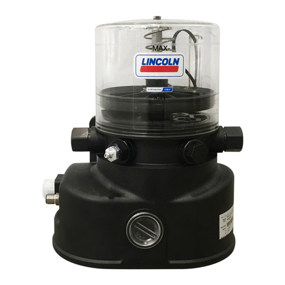
3. Overview, functional description 3. Overview, functional description 3.1 Described versions P502 with follower plate Fig. 1 P502 without follower plate Fig. 2 - with follower plate and low level signal (1XLF) - without follower plate and without low level signal... - Page 19 3. Overview, functional description Overview P502 with follower plate Fig. 3 1 Reservoir The lubricant is stored in the reservoir. De- pending on the pump version there are three different types of reservoirs. XN 1 L for lubricating grease YN 1 L for lubricating oil XLF 1 L with follower plate and low level signal for lubricating grease.
- Page 20 3. Overview, functional description Overview P502 with follower plate Fig. 4 4 Closure screw When using the pump with one pump element only make sure to close the connection port for the second pump element with a closure screw. 5 Filler fitting (R1/4) The filler fitting serves to fill the reservoir with lubricant.
- Page 21 3. Overview, functional description 9 Pump element Overview P502 with follower plate Fig. 5 There can be mounted a maximum of 2 pump elements. The pump elements are actuated by the motor via an eccentric shaft. The pump elements generate the operating pressure and supply the lubricant out of the reservoir to the connected lubrication feed lines.
- Page 22 3. Overview, functional description Overview P502 Fig. 6 11 Control pcb All control pcbs are equipped with an EEPROM. Thus the pcb's data are protected against loss. As soon as the pump is switched off, after switching the pump on again the pause time respectively the lubrication time will continue from where it had been interrupted.
- Page 23 3. Overview, functional description Overview P502 Fig. 7 26 Stirring paddle The stirring paddle homogenizes and planes the lubricant. Transportability of the lubricant is improved and bleeding is reduced.
-
Page 24: Technical Data
4. Technical data 4. Technical data 4.1 General technical data Admissible operating temperature -25 °C to 70 °C Operating pressure 270 bar max. Reservoir size 1 litre via hydraulic lubrication fitting Filling of reservoir (optionally via cartridge with fitting or filling connection) Lubricants Lubricating greases NLGI II and NLGI III / fluid greases NLGI 00, 000... -
Page 25: Electrics
4. Technical data 4.2 Electrics Supply voltage 12 V DC 24 V DC Current consumption 6.5 A maximum 3 A max. Tolerance of input voltage -20 / + 30 % -20 / + 30 % Inputs protected against reverse polarity, short circuit proof, non-isolated IP type of protection Square plug IP 6K9K... -
Page 26: Factory Settings Of Lube And Pause Times Of Pumps With Control Pcb
4. Technical data 4.4 Factory settings of the lubrication and pause times of pumps with control pcb Lubrication and pause times Lubrication time 6 min The red rotary switch on the control pcb is in position 3 pause time 6 hrs The blue rotary switch on the control pcb is in position 6 Low level signal After a low level signal the run time is 4 min max. -
Page 27: Possible Settings Of Lube And Pause Times Of Pumps With Control Pcb
4. Technical data 4.6 Possible settings of the lubrication and pause times of pumps with control pcb Position of the rotary switch (blue) 48 52 Pause time in minutes Position of the rotary switch (blue) Pause time in hours Position of the rotary switch (red) Lubrication time in seconds 104 112 Position of the rotary switch (red) -
Page 28: Tightening Torques
4. Technical data 4.7 Tightening torques Adhere to the following tightening torques when installing or repairing the pump. Pump with base plate, machine, or vehicle Pump element with pump housing Counter nut at the adjustable pump element Pressure reducing valve in the pump element Lubrication fitting/ adaptor for lubrication fitting Closure screw on housing cover Reservoir on Reservoir axis... -
Page 29: Useable Reservoir Volume
4. Technical data 4.9 Useable reservoir volume Reservoir 1XN (without follower plate and without low level indication) Regarding reservoir version 1XN the useable reservoir volume mainly depends on the NGLI consistency class and the operating temperature of the lubricant to be used. In case of high consistency and low operating temperature normally more lubricant sticks to the inner surfaces of the reser- voir/ pump and is thus no more available for being dispensed. -
Page 30: Notes Related To The Type Identification Plate
4. Technical data 4.10 Notes related to the type identii- 4.11 Notes related to the CE marking cation plate CE marking is effected following the requirements of the applied directives: The type identification plate states impor- ○ 2014/30/EU Electromagnetic compatibility tant characteristics such as type designa- ○... -
Page 31: Type Identification Code
4. Technical data 4.12 Type identiication code Identification code P502 - 1XN - 2K6 - 12 - 2A - 6 - 14 - V10 Basic type of pump Control pcb's P502 (without control pcb) (supply voltage, terminals 15+31) V10 - V13 (supply voltage, terminals 15+30+31) -
Page 32: Delivery, Returns, And Storage
5. Delivery, returns, and storage 5. Delivery, returns, and storage 5.2 Returns 5.3 Storage 5.1 Delivery Clean all parts and pack them properly SKF products are subject to the following The products are packaged following the before returning them. Protect the product storage conditions: standard commercial practice according to ○... -
Page 33: Assembly
6. Assembly 6. Assembly 6.1 General information NOTICE Only qualified technical personnel may Technical data (see chapter 4). install, operate, maintain, and repair the products described in these Instructions. Qualified technical personnel are persons 6.2 Attachment who have been trained, assigned, and in- Protect the product against humidity and structed by the operator of the final product, vibration and install it in an easily accessible... -
Page 34: Minimum Assembly Dimensions
6. Assembly 6.3 Minimum assembly dimensions Ensure sufficient space for maintenance work or for a possible disassembly of the product by leaving a free space of at least 50 mm into each direction in addition to the stated dimensions. Minimum assembly dimensions Fig. 10 A = height 270 mm B = width... -
Page 35: Connecting Dimensions
6. Assembly 6.4 Connecting dimensions Connecting dimensions Fig. 11 The pump is fastened on the two mounting bores (27). Fastening is done by means of the fastening material included in the scope A = height 114 mm of delivery. B = distance 140 mm 2 x M8 screw C = bore Ø... -
Page 36: Installing The Pump Elements
6. Assembly 6.5 Installing the pump elements Mount pump elements Fig. 12 • Remove closure screw (4). • Screw in pump element (9) with new sealing ring. Tightening torque = 20 Nm • Repeat procedure for each pump element. -
Page 37: Installing The Pressure Reducing Valves
6. Assembly 6.6 Installing the pressure reducing valves Mount pressure reducing valve Fig. 13 • Choose pressure reducing valve (13) in accordance with the max. operating pressure. • Remove blind plug from pump element (9). • Screw pressure reducing valve (13) into pump element (9). -
Page 38: Installing The Centralized Lubrication System
6. Assembly 6.7 Installing the centralized lubrication Mount the centralized lubrication system Fig. 14 system • Fasten the pump. Observe connecting dimensions (see chapter 6.4). Tightening torque = 18 Nm • Make up the divider. • Fasten the divider. • Make up the lines and attach them to the pump and, if applicable, to the superior machine. -
Page 39: Electrical Connection
6. Assembly 6.8 Electrical connection Bayonet plug • Use adequate cable to conigure bayonet Electrical connections must be done in such way that no forces are transferred to the plug without cable. For connection see corresponding wiring diagram in these product (tension-free connection). For elec- Instructions (see chapter 12). -
Page 40: Priming Without Follower Plate
Overilling of the reservoir during the filling procedure. manner. Consider lubricant expansion by increased temperature (important, e.g. for storage or transport of the pump) or by pressure relief after the filling procedure (reservoir vent clogged by lubricant). P502 without follower plate Fig. 15... -
Page 41: Priming With Follower Plate
6. Assembly 6.10 Priming with follower plate • Switch on filler pump and completely Vented space under the follower plate Fig. 17 NOTICE fill space below the follower plate with lubricant (see Fig. 17). The space is fully Avoid air pockets under the follower plate. filled as soon as the follower plate starts These result in poor or lacking pump lifting. - Page 42 6. Assembly • Slowly pull cable strap (30) out of reser- • Slowly pull cable strap (30) out of reser- Vented space under the follower plate Fig. 20 voir vent (7) to vent the space below the voir vent (7) to vent the space below the follower plate.
-
Page 43: Setting Of Lubrication And Pause Times
6. Assembly 6.11 Setting of lubrication and pause times 6.11.2 Pumps with control pcb 6.11.1 Pumps without control pcb Setting of lubrication and pause times Fig. 22 • Setting or modification of the lubrication Setting or modification of the lubrication and pause times is effected via the inter- and pause times is effected via the external nal control pcb. -
Page 44: Jumper Settings
6. Assembly 6.11.3 Jumper settings Jumper position on the control pcb NOTICE Pause time Lubrication time Jumper position for Jumper position Damage to the pump Control bridge Pause and lu- 2-30 4 - 60 1 - 15 8-120 The positions of the jumpers on the control Terminal 15/30 brication time min. -
Page 45: Start-Up
7. Start-up 7. Start-up 7.1 General information Setting of lubrication and pause times Fig. 23 ○ No loose or missing parts. Start-up of the fully and correctly mounted ○ No damages, deformations, or cracks. pump is effected via the machine contact or ○... -
Page 46: Operation, Shutdown And Disposal
8. Operation, shutdown and disposal 8. Operation, shutdown and disposal 8.1 General information Filling via filler fitting Filling the reservoir Fig. 24 After correct electrical connection and filling • Unscrew closure screw from filling con- with lubricant the pump is ready for opera- nection (8). -
Page 47: Maintenance, Cleaning And Repair
9. Maintenance, cleaning and repair 9. Maintenance, cleaning and repair 9.1 General information 9.4 Replacement of pressure relief valves Replacement of pump element and and pump elements pressure relief valve Fig. 26 Liability is excluded for any damage or faults arising from inappropriate maintenance, •... -
Page 48: Replacement Of The Control Pcb
9. Maintenance, cleaning and repair 9.5 Replacement of the control pcb • Verify the lubrication and pause times of Replacement of the control pcb Fig. 28 CAUTION the new control pcb and adjust, if neces- sary (see chapter 4.5). Electric shock •... -
Page 49: Tests After Replacement Of The Control Pcb
9. Maintenance, cleaning and repair 9.6 Tests after replacement of the control 9.7 Disposal of disassembled parts After replacement of the control pcb Electrical functionality test Electrical components: carry out an electrical test according to Dispose of or recycle electrical components ○... -
Page 50: Replacement Of Reservoir With Follower Plate
9. Maintenance, cleaning and repair 9.8 Replacement of reservoir with follower plate • Mount the spring (25) into the corre- Tightening torque = 2+1 Nm • Switch the pump off and disconnect it sponding lug on top of the new reservoir. •... -
Page 51: Replacement Of The Follower Plate
9. Maintenance, cleaning and repair 9.9 Replacement of the follower plate • Switch the pump off and disconnect it • Position the reservoir (1) on the pump. • Fill reservoir with lubricant again (see from the electrical grid. If necessary, Make sure to guide the spring (25) over chapter 6.10). -
Page 52: Replacement Of Reservoir Without Follower Plate
9. Maintenance, cleaning and repair 9.10 Replacement of reservoir without follower plate • Lightly oil the new O-rings (23) and • Tighten reservoir (1) with new screw (22) • Switch the pump off and disconnect it mount them into the corresponding and washer on the reservoir axis (24). -
Page 53: Troubleshooting
10. Troubleshooting 10. Troubleshooting Pumps with and without control unit (Motor of pump runs, but pump does not supply lubricant) Possible cause Visible Remedy ○ Error code F 1 Reservoir empty ○ Fill reservoir ○ Visual check Air pockets in the lubricant ○... - Page 54 10. Troubleshooting Pumps with control unit (Motor of pump does not run) Possible cause Visible Remedy Fault in the superior machine or vehicle ○ See description of the machine or vehicle. ○ See description of the machine or vehicle. ○ Check lines, control pcb, fuses, motor, ○...
- Page 55 10. Troubleshooting Pumps without control unit (Motor of pump does not run) Possible cause Visible Remedy ○ Possible verification of the function by trig- The pump is in the pause time mode ○ No pump noise gering an additional lubrication cycle ○...
-
Page 56: Display Of The Operating States And Fault Conditions By Means Of The Control Pcb's Leds
10. Troubleshooting 10.1 Display of the operating states and fault conditions by means of the control pcb's LEDs In case of pumps with control pcb the operating states and fault conditions are displayed by different display patterns of the green and red LEDs on the control pcb. - Page 57 10. Troubleshooting Error code F3: Z key (additional lubrication) (green LED is permanently lit, red LED flashes the first 3 seconds for 0.25 seconds, then there is a pause of 3 seconds) 1. second 2. second 3. second 4. second 5.
-
Page 58: Spare Parts
11. Spare parts 11. Spare parts The spare parts may be used exclusively for replacement of identical defective parts. Modifications on existing pumps (except from the pump elements) are not allowed. 11.1 Pump elements (including sealing ring) Designation Qty. Part no. Pump element Fig. -
Page 59: Spare Parts Kit For Replacement Of The Reservoir
Spare parts kit of reservoir Fig. 39 Designation Qty. Part no. Spare parts kit for replacement of reservoir 558-33908-1 Consisting of: Reservoir P502 Logo O-ring Sealing for reservoir screw Reservoir screw 11.5 Spare parts kit for replacement of the follower plate... -
Page 60: Spare Parts Kit For Replacement Of The Screw Cap
11. Spare parts Spare parts kit of control pcb Fig. 41 11.6 Spare parts kit for replacement of the control pcb Designation Qty. Part no. Spare parts kit for replacement of control pcb 558-34877-5 Consisting of: Control pcb 12/24 V DC Housing cover Sealing for housing cover Screws for housing cover... -
Page 61: Circuit Diagrams
12. Circuit diagrams 12. Circuit diagrams 12.1 Legend Cable colours following IEC60757 Abbreviation Colour Abbreviation Colour Abbreviation Colour Abbreviation Colour black green white pink brown yellow orange turquoise blue violet Components Abbreviation Meaning Abbreviation Meaning Plug for connection A1 Low level indication Plug for connection A2 Low level indication with pre-warning Plug for connection of low level indication... -
Page 62: Core Assignment Of The Connection Plugs
12. Circuit diagrams 12.2 Core assignment of the connection plugs Core assignment of connection A2/ X2 Core assignment of connection A1 / X1 Core assignment of connection A1 / X1 Pin 1 Pin 2 Pin 3 Pin 4 Pin 5 Pin 1 Pin 2 Pin 3... -
Page 63: Assignment Of Circuit Diagrams To The Pump
12. Circuit diagrams 12.3 Assignment of circuit diagrams to the pump Type identification code Item 1 Item 2 Item 3 Item 4 Item 5 Item 6 Item 7 Item 8 Assignment of the circuit diagrams to a PXXX 12/24 certain pump is done via the characteristics given in the type identification code Item 4 Power supply... -
Page 64: Circuit Diagram 12/ 24 V Dc, With Bayonet Plug And Control Pcb V20
12. Circuit diagrams 12.4 Circuit diagram 12/ 24 V DC, with bayonet plug and control pcb V20 Circuit diagram 12/ 24 V DC, with bayonet plug and control pcb V20 Fig. 41 Valid for type identification code P502-XXXX-XXX-12-1A7-XX-V20 P502-XXXX-XXX-24-1A7-XX -V20... -
Page 65: Circuit Diagram 12/ 24 V Dc, With Bayonet Plug And Control Pcb V10
12. Circuit diagrams 12.5 Circuit diagram 12/ 24 V DC, with bayonet plug and control pcb V10 Circuit diagram 12/ 24 V DC, with bayonet plug and control pcb V10 Fig. 42 Valid for type identification code P502-XXXX-XXX-12-1A7-XX-V10 P502-XXXX-XXX-24-1A7-XX -V10... -
Page 66: Circuit Diagram 12/ 24 V Dc, With Square Plug And Control Pcb V20
12. Circuit diagrams 12.6 Circuit diagram 12/ 24 V DC, with square plug and control pcb V20 Circuit diagram 12/ 24 V DC, with square plug and control pcb V20 Fig. 43 Valid for type identification code P502-XXXX-XXX-12-2A1-XX-V20 P502-XXXX-XXX-24-2A1-XX-V20 P502-XXXX-XXX-12-1A1-XX-V20 P502-XXXX-XXX-24-1A1-XX-V20... -
Page 67: Circuit Diagram 12/ 24 V Dc, With Square Plug And Control Pcb V10
12. Circuit diagrams 12.7 Circuit diagram 12/ 24 V DC, with square plug and control pcb V10 Circuit diagram 12/ 24 V DC, with square plug and control pcb V10 Fig. 44 Valid for type identification code P502-XXXX-XXX-12-2A1-XX-V10 P502-XXXX-XXX-24-2A1-XX-V10 P502-XXXX-XXX-12-1A1-XX-V10 P502-XXXX-XXX-24-1A1-XX-V10... -
Page 68: Circuit Diagram 24 V Dc, With M12 Plug And Control Pcb V20
12. Circuit diagrams 12.8 Circuit diagram 24 V DC, with M12 plug and control pcb V20 Circuit diagram 24 V DC, with M12 plug and control pcb V20 Fig. 45 Valid for type identification code P502-XXXX-XXX-24-2A2-XX-V20... -
Page 69: Circuit Diagram 24 V Dc, With M12 Plug Without Control Pcb
12. Circuit diagrams 12.9 Circuit diagram 24 V DC, with M12 plug without control pcb Circuit diagram 24 V DC, with M12 plug without control pcb Fig. 46 Valid for type identification code P502-XXXX-XXX-24-1A2-XX-... -
Page 70: Circuit Diagram 12/ 24 V Dc, With Square Plug Without Control Pcb
12. Circuit diagrams 12.10 Circuit diagram 12/ 24 V DC, with square plug without control pcb Circuit diagram 12/ 24 V DC, with square plug without control pcb Fig. 47 Valid for type identification code P502-XXXX-XXX-12-1A1-XX- P502-XXXX-XXX-24-1A1-XX- P502-XXXX-XXX-12-1A2-XX- P502-XXXX-XXX-24-1A2-XX-... -
Page 71: Circuit Diagram 12/ 24 V Dc, With Bayonet Plug Without Control Pcb
12. Circuit diagrams 12.11 Circuit diagram 12/ 24 V DC, with bayonet plug without control pcb Circuit diagram 12/ 24 V DC, with bayonet plug without control pcb Fig. 48 Valid for type identification code P502-XXXX-XXX-12-1A5-XX- P502-XXXX-XXX-24-1A5-XX-... -
Page 72: Circuit Diagram 12/ 24 V Dc, With Bayonet Plug Without Control Pcb
12. Circuit diagrams 12.12 Circuit diagram 12/ 24 V DC, with bayonet plug without control pcb Circuit diagram 12/ 24 V DC, with bayonet plug without control pcb Fig. 49 Valid for type identification code P502-XXXX-XXX-12-1A5-XX- P502-XXXX-XXX-24-1A5-XX-... -
Page 73: Notes
Notes... - Page 74 The Power of Knowledge Engineering Bearings Drawing on five areas of competence and application-specific expertise amassed over more than 100 Lubrication Seals and bearing years, SKF brings innovative solutions to OEMs and production facilities in every major industry world- systems units wide.
Need help?
Do you have a question about the P502 and is the answer not in the manual?
Questions and answers