Table of Contents
Advertisement
Advertisement
Table of Contents

Related Manuals for Lincoln Quicklub


Summary of Contents for Lincoln Quicklub
- Page 1 ® Quicklub Maintenance 2/16/2009 ASC FORM# 80-1088 REV 7/11/2014...
-
Page 2: Table Of Contents
Contents Pages Introduction------------------------------------------------------------------------------------------ 3 Benefits from Automated Lubrication ------------------------------------------------------ 3 The Lincoln Quicklub Pump-------------------------------------------------------------------- 3 Glossary of Terms --------------------------------------------------------------------------------- 4 - 5 System Operation (Non-Monitored) --------------------------------------------------------- 6 System Operation (Monitored) ---------------------------------------------------------------- 7 Divider Valve Operation ------------------------------------------------------------------------- 8 System Startup ------------------------------------------------------------------------------------- 9... -
Page 3: Introduction
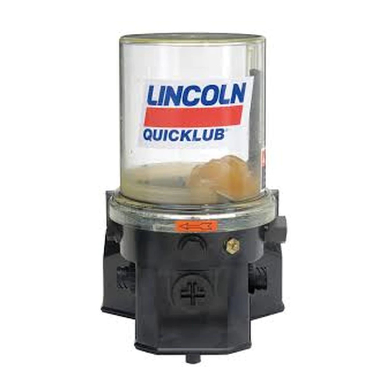
When a Lincoln lube system is installed, quality and system robustness is the number one priority. Quicklub lubrication systems are proven to increase the life of pins and bushings, and decrease labor costs associated with manual lubrication. When a system is installed, items such as machine articulation, type of material machine handles, climate, and other operating conditions that could damage the system are taking into consideration. -
Page 4: Glossary Of Terms
Distribution block – See divider valve Divider Valve – ® A Quicklub divider valve is a proportioning device consisting of a minimum of three pistons. A primary divider valve is the first divider valve downstream from the lube pump. A secondary divider valve is any divider valve receiving lubricant from the primary divider valve. - Page 5 A cycle consists of the piston moving two times (out and back). Pushbutton – Optional accessory on Quicklub systems that alerts the operator of a fault and allows the operator to trigger an additional lubrication cycle. Usually mounted in the cab for visibility.
-
Page 6: System Operation (Non-Monitored)
System Operation (Non-Monitored System) The key components of the Quicklub Non-Monitored system are: 1. Pump with an Integrated Timer. The Integrated timer controls the “On Time” and “Off Time” of the pump. 2. Divider valve network consisting of a Primary Valve and Secondary Valves with attached Cycle Indicator Pin. -
Page 7: System Operation (Monitored)
System Operation (Monitored System) The key components of the Quicklub Monitored system are: 1. Pump with an Integrated Timer. The Integrated timer controls the “Off Time” of the pump. 2. Divider valve network consisting of a Primary Valve and Secondary Valves with attached Cycle Indicator Pin. -
Page 8: Divider Valve Operation
Divider Valve Operation At the heart of every Quicklub System is the metering valve or progressive distributor block, designed to positively meter the input of lubricant (oil up to NLGI #2 greases) out to the connected number of lubrication points irrespective of distance and back pressure. The inlet passageway is connected to all piston chambers at all times with only one piston free to move at any one time. -
Page 9: System Startup
The following checklist has been developed as an aid in verifying proper installation and operation of the Quicklub Onboard Grease System. By completing the steps outlined below, the operational readiness of the system and resulting extension of the component life of all points connected to the system will be insured. -
Page 10: Daily Walk-Around Inspection
Daily Walk-Around Inspection The Lincoln Industrial Quicklub automated lube system components are designed, engineered, manufactured and assembled to the highest or quality standards. This lube system requires little or nor maintenance, however, to ensure maximum reliability and to realize maximum service life of all components, it is recommended that a daily walk-around inspection be performed. - Page 11 2/13/09...
-
Page 12: Troubleshooting A Blockage
This abnormally higher pressure that is a result of a blockage is limited, isolated, and signaled through the use of various performance indicators, reset and relief, incorporated into the system design. If a blockage exists in a Quicklub lubrication system it is caused by one of the following reasons: (1) Crushed transmission line in the System. - Page 13 Cleaning the divider valve will usually result in only temporarily solving the problem. Consult your lubricant supplier for recommendations on alternate lubricants and your local Lincoln Distributor to verify compatibility with centralized lubricating systems.
- Page 14 Quick-Fill Adapter Installation and Operation (Filling pump reservoir) Step 1: To install the quick-fill adapter, remove the The Quick-Fill adapter is a device which replaces the standard grease fitting fill port with a high-flow standard fill port located in the front of the pump. port for use with a standard grease gun.
- Page 15 Monitored & Non-Monitored Pump Indicator LED’s The 203 style Monitored and Non-Monitored pumps have LED’s on the circuit board that indicate the pump is receiving power to the circuit board and that the pump is actually pumping grease. The PC board is accessed by removing the plastic plug located on the front of the pump.
- Page 16 Non-Monitored Pump The non-monitored pumps have two rotary dial switches on the PC board to set the On and Off time. “On Time” is how long the pump will run and the “Off Time” is the interval between run times. The Blue dial on the left sets the Off or Pause time.
- Page 17 TIMER OPERATION The Off timer begins accumulating time when the ignition switch closes. When the Off timer reaches the preset value the pump will turn on. The pump remains activated for the period of time that is preset on the On timer. When the ignition switch opens the Off timer will retain its accumulated time for a period of five days.
-
Page 18: Pushbutton Fault Light Indicator
Pushbutton Fault Light Indicator An optional pushbutton/fault light can be mounted in the cab that monitors the status of the lube system. The LED uses different flashing frequencies depending on the status of the lube system (i.e. running, not running or in fault). The service manual for the particular pump will show what fault is associated with each flashing frequency. -
Page 19: Manually Lubricating Bearings
There is a grease fitting located on all of the divider valves in a Quicklub system. Use a grease gun and attach the hose to the grease fitting. As grease is pumped into the valve, the bearings will be lubricated and the cycle indicator pin on the side of the divider valve will be cycling in and out. -
Page 20: Remote Lube Fitting
Remote Fill Lube Fitting Some large equipment requires that a Remote Fill fitting to be installed so the operator can refill the pump reservoir without having to climb on the equipment to access the pump. An example of when a remote fill fitting is used is excavators where the pump is mounted up high behind the cab. -
Page 21: Spiral Wrap (Protection For Lube Lines)
Spiral Wrap / Spring Coil / Sleeving Below are different kinds of line protection offered in a Quicklub system. Depending on the application determines the kind of line protection required. Many times it is necessary for lines to be exposed to articulation, falling debris, abrasion, heat, etc. - Page 22 Grease Line Guarding The following shows the different types of guarding that are used to protect grease lines. Again, depending on the application will determine the required guarding. Additional guarding should be used for machines that operate in extreme conditions. Always check with the customer before welding or altering the machine.
- Page 23 Grease Line Guarding (continued) The following is another type of guarding that is used to protect lube lines on heavy construction equipment. It is attached to the frame using welded studs or stand-offs. Guarding that can be bent to fit around obstacles Straight Guarding Guarding shown used on an excavator to protect lube lines in heavy use areas.
-
Page 24: Tapping Lubrication Points
Tapping Lubrication Ports (if necessary) It is sometimes necessary to re-tap a lubrication port due to port damage or drive type fitting removal. Tapping oil should be used to ease the tapping process. Make sure that all metal filings are removed from the port prior to installing the fitting.
Need help?
Do you have a question about the Quicklub and is the answer not in the manual?
Questions and answers