Table of Contents
Advertisement
Advertisement
Table of Contents

Related Manuals for Avery Weigh-Tronix 2060


Summary of Contents for Avery Weigh-Tronix 2060
- Page 1 Model 2060 Universal Weight Indicator User Instructions AWT35-501506 Issue AB...
- Page 2 This publication was correct at the time of going to print, however Avery Weigh-Tronix reserves the right to alter without notice the specification, design, price or conditions of supply of any product or service at any time.
-
Page 3: Table Of Contents
Additional Connectors ....................27 I/O Connector Pins (9 pin connector) ................ 27 Chapter 4 Quick Start Calibration Guide ....................28 Calibrate the 2060 with a Standard Configuration Number ..........28 Determine the Configuration Number ................ 28 Configuration Codes ....................30 Enter the Configuration Code Number Parameter (Cfg Num) ........ - Page 4 Configuring the 2060 for Other Brand Weigh Bars and Loadcells ........40 Custom Calibration Number ..................40 Chapter 5 Menus ............................42 Accessing the menus ....................... 42 Menu Navigation ...................... 43 Exiting the Menus ......................43 User menu ........................45 The User submenu ....................
- Page 5 Options ........................81 Opt232 ........................81 USB ........................... 81 Chapter 6 Application menu ........................82 Accessing the Application menu ..................83 Auto Settings ........................84 Totals Settings ......................... 85 App Settings ........................85 App Info ..........................86 Model 2060 User Instructions...
- Page 6 Model 2060 User Instructions...
-
Page 7: Chapter 1 General Information And Warnings
CAUTION! This is a Caution symbol. Cautions give information about procedures that, if not observed, could result in damage to equipment or corruption to and loss of data. Model 2060 User Instructions... -
Page 8: Installation
ATTENTION: Il y a danger d'explosion s'il y a remplacement incorrect de la batterie, remplacer uniquement avec une batterie du même type ou d'un type équivalent recommandé par le constructeur. Mettre au rebut les batteries usagées conformément aux instructions du fabricant. Model 2060 User Instructions... -
Page 9: Routine Maintenance
CAUTION: Do not weld on or near the 3060 or any part of the scale system such as Weigh Bars. Excessive heat and / or high currents may cause internal damage. Physically remove the 2060 from any equipment it is mounted to and disconnect it from the power source. Make ground connection as far away from any scale part (cables, Weigh Bar, etc.) as possible. -
Page 10: Sharp Objects
Classe A prescrites dans le Règlement sur le brouillage radioélectrique edicté par le ministère des Communications du Canada. European Countries WARNING: This is a Class A product. In a domestic environment, this product may cause radio interference in which the user may be required to take adequate measures. Model 2060 User Instructions... -
Page 11: Declaration Of Conformity
1.8 Declaration of Conformity Model 2060 User Instructions... -
Page 12: Chapter 2 Overview
Overview This manual covers the installation, connections and configuration of the Model 2060 indicator. The 2060 can connect to USB flash drives, printers, remote displays, computers and other peripheral devices. Communications- Two standard RS-232 with optional third bi-directional serial ports w/selectable output formats –... -
Page 13: Front Panel Keys
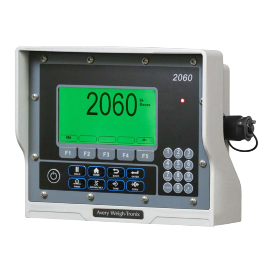
2.1.1 Front Panel Keys The 2060 front panel shown in Figure 2.1 consists of the keys and the display. Never press a key with anything but your finger. Damage to the overlay may result if sharp or rough objects are used. -
Page 14: Home Screen
The 0 key toggles between 0 and a space. 2.5 Menus Menus used to configure the 2060 are accessed with passwords. See Menus on page for a complete overview of each menu and how to navigate through them. -
Page 15: Standard Print Formats
2.6 Standard Print Formats The Model 2060 has 10 available print formats. See the examples below. Format 0 G: 32010 lb Format 1 G: 32010 lb T: 16010 lb N: 16000 lb Format 2 04-26-2006 03:02:47 G: 32010 lb Format 3 (default) - Page 16 Format 5 32010 , 16010 , 16000 Format 6 04-26-2006,03:02:47, 32010 Format 7 04-26-2006,03:02:47, 32010 , 16010 , 1600 Format 8 N: 16000 lb Format 9 04-26-2006 03:02:47 N: 16000 lb Model 2060 User Instructions...
-
Page 17: Chapter 3 Installation
The following section will cover installing the Model 2060 and cable connections. 3.1 Mounting the Model 2060 The Model 2060 mounts on a quick-detach V bracket or a 1.5" Ram Mount. 3.1.1 Instructions for V mount Weld or bolt the quick-detach bracket into place, as follows:... -
Page 18: Cable Connections And Power Requirements
Bolt one of the 2.5" Ram Mount bases onto the 2060 V mount bracket. It is recommend to bolt the Ram mount onto the Bracket so the V part of the bracket will point towards the 2060 (reverse of how the bracket would be mounted to use as a V mount). -
Page 19: Connectors
I/O Connector (9 pin) Description Description +12V - Bridge + Excitation + Bridge Input 2 (ZERO) - Excitation Input 3 (RESET target) Shield Outside View (Female) Output 1 Outside View Output 2 (N.O) (Male) Input 1 (TARE) Model 2060 User Instructions... -
Page 20: Routing The Scale Interface Cable
If you have a tinned lead power supply and want to connect to the auxiliary power you need to add a spade to each wire. Connect the white wire to the key-switched or unswitched power spade. Connect the black wire to the ground spade. Model 2060 User Instructions... -
Page 21: Power Connections - Battery
Disconnect the negative wire from the battery terminal before performing any electrical work. Loosely attach the connector end of the power cable to the 2060 indicator. Route the cable to the desired power source connection point. If possible, run the power cable through existing holes and channels so that it will be out of the way and cannot be damaged by any moving parts. - Page 22 Tighten the AMP or AWT connector on the underside of the indicator. See figure 3.2. Reconnect battery power. Press and hold the On/Off key on the 2060 until the red light above the key comes on. Check that the instrument powers on.
-
Page 23: Wiring 2060 Indicator To Equipment Power Systems
3.6 Wiring 2060 Indicator to Equipment Power Systems In all cases it is advised that you consult the equipment manufacturer or authorized agents for advice before installing a weighing system. These are configurations that you may find on different equipment manufacturers models. -
Page 24: Volt Power Systems
12V from the ground connection. If there is an accidental connection from the indicator housing to the equipment metal work then there will be a large fault current which will cause the power cable 0V wire to heat up. Model 2060 User Instructions... -
Page 25: Power Connections - Ac
Inspect the cable run and make sure that the cable is not pinched, kinked or in the way of moving parts or sharp objects. Model 2060 User Instructions... -
Page 26: Optional Communications Connections
Tighten the AMP connector on the underside of the indicator. Plug the AC adapter in to the outlet. Press and hold the On/Off key on the 2060 until the red light above the key comes on. Check that the indicator powers on. -
Page 27: Additional Connectors
Reconnect power to the indicator and device. Press and hold the On/Off button on the 2060 until the red light comes on and the indicator powers on. 3.8.1 Additional Connectors The 2060 also has the following connectors: USB connector - located on the right side of the enclosure. Use the USB connector to connect a USB keyboard or flash drive. -
Page 28: Chapter 4 Quick Start Calibration Guide
This section covers the standard calibration process for the scale system using pre- calibrated Avery Weigh-Tronix weigh cells. If using other brands of weigh cells or configurations of AWTX weigh cells not mentioned below you will need to use Custom Configuration. - Page 29 3rd DIGIT Figure 4.3 3rd Digit (Capacity and Increment Size) The fourth digit is for print formats. The 2060 print formats are determined by the application so the 4th digit will always be 0. The 5th digit solely selects lb or kg in this example we want kg so the 5th digit becomes 4.
-
Page 30: Configuration Codes
4.1.2 Configuration Codes The following tables show how to establish a Configuration Code Number (CCN) to configure the 2060 indicator. Table applies to all 3 Weigh Bar junction box systems and 4 Weigh Bar junction box systems. The only exception is the Calibration Size 2 1/4D-P, which can be used with 8 Weigh Bars that are 2 1/4 D cal size. -
Page 31: Enter The Configuration Code Number Parameter (Cfg Num)
The fourth digit is for print formats. The 2060 print formats are determined by the application so the 4th digit will always be 0. Table 4.2 4th CCN Digit (Print Format) Print Formats Digit The 5th digit selects the calibration unit; lb (0) or kg (4). -
Page 32: Configuration Code Numbers For Common Applications
After several attempts at a code number, if the scale still does not weigh properly please consider the following: Contact your dealer or distributor where the scale was purchased. Access the Avery Weigh-Tronix website at www.agscales.com for more debugging tips. Contact the Avery Weigh-Tronix service department at 1-800-458-7062 for assistance. -
Page 33: Custom Configuration Number For Awtx Weigh Bars
3rd DIGIT Figure 4.5 3rd Digit (Capacity and Increment Size) The fourth digit is for print formats. The 2060 print formats are determined by the application so the 4th digit will always be 0. The 5th digit selects the calibration unit; lb (0) or kg (4). -
Page 34: Determine Custom Calibration Number
4.2.2 Determine Custom Calibration Number This number will be entered in the CUSTOM Configuration parameter which appears as Cust.Cfg in the 2060 menu. In this example we have 6 2 ½ Cal Size weigh bars. Figure is an excerpt from Table 4.4:Custom Number... - Page 35 2 1/8 30026 13619 2 1/4 4613 2092 2 1/4 9226 4185 2 1/4 13839 6277 2 1/4 18452 8370 2 1/4 23065 10462 2 1/4 27678 12554 2 1/4 32291 14647 2 1/4 36904 16739 Model 2060 User Instructions...
- Page 36 84214 212183 96245 Alley Weigh bar Alley Weigh bar Alley Weigh bar 1167 Alley Weigh bar 1556 Alley Weigh bar 1946 Alley Weigh bar 2335 1059 Alley Weigh bar 2724 1235 Alley Weigh bar 3113 1412 Model 2060 User Instructions...
- Page 37 CC-30-3 20000 9072 CC-30-3 24000 10886 CC-30-3 28000 12701 CC-30-3 32000 14515 CC-50 8000 3629 CC-50 16000 7257 CC-50 24000 10886 CC-50 32000 14515 CC-50 40000 18144 CC-50 48000 21772 CC-50 56000 25401 CC-50 64000 29030 Model 2060 User Instructions...
-
Page 38: Enter Configuration Code Number (Cfg Num)
The Calib menu will be highlighted. Press the F3/ .key. If you have Avery Weigh-Tronix Ag Weigh Cells you can chose between standard and custom calibration codes to calibrate your system. If you are using weighs from a different manufacturer you will want to go to section for custom calibration. -
Page 39: Custom Configuration Number Calibration
If we where 2% to high we simply would lower the custom number by 2% (38,559x.98=37,787.82) Step 4: Verify if the next load is within 1% of the Calibrated Truck scale. If it is not within 1% you can repeat the process above. Model 2060 User Instructions... -
Page 40: Configuring The 2060 For Other Brand Weigh Bars And Loadcells
4.3 Configuring the 2060 for Other Brand Weigh Bars and Loadcells The 2060 will work with any brand of strain gage based weigh bar or load cell. Once the system is installed, the 2060 will then need to be calibrated using the Configuration Code Number (Cfg Num) and (Cust.Cfg). - Page 41 Model 2060 User Instructions...
-
Page 42: Chapter 5 Menus
Sometimes there may be no sub level or there maybe two sub levels before you get to a list of items to set. You will see on-screen lists with instructions on how to choose and set an item in each menu list. On-screen prompts guide you as you move through the menus. Model 2060 User Instructions... -
Page 43: Menu Navigation
Use the Esc key or the BACK key to exit a menu or go back one level. 5.2 Exiting the Menus From the menu, press the F1/ key repeatedly until the following screen is displayed: SAVE no is highlighted by default. Model 2060 User Instructions... - Page 44 SAVE no - Do not save changes and exit to the home screen SaveYES - Save changes and exit to the home screen CAnCEL - Remain in the menu Press the F3/ key to accept the highlighted choice. Model 2060 User Instructions...
-
Page 45: User Menu
24HR - Shows time in the 24 hour style No matter which style you pick, time must always be entered in the 24 hour style. The display of the time will follow the style you pick. Model 2060 User Instructions... -
Page 46: The About Submenu
See the serial number of the indicator. Option Bus 1 - Choose the Bus of the option card. Only one Bus available on the ZK840. Card 1 or 2 - Choose the Card you want to view. Model 2060 User Instructions... -
Page 47: The Audit Submenu
USB. Printing to USB will create a folder on the flash drive and a comma separated file with the data. You can exit the menu by following the instructions in Exiting the Menus on page Model 2060 User Instructions... -
Page 48: Diag Menu
This stands for current zero and represents the weight offset between the calibration zero setting and the current zero setting due to pushbutton zero or Auto-Zero Tracking (AZT) adjustments. Select to view values for Scale 1 through Scale 5, if installed. Value View the zero offset. Model 2060 User Instructions... -
Page 49: Display
If no USB device is plugged in when you begin the test, Open is briefly displayed, then No USB is briefly displayed, then USB. 5.4.6 Inputs The input test is used to verify if external switches wired to the input ports on TB2 are functioning properly. Model 2060 User Instructions... -
Page 50: Outputs
Press UNITS to go to the next output. Repeat the steps to test output 2 and 3. When finished, press TARE … Outputs is displayed. 5.4.8 Options Use this to see the name of installed option cards. Model 2060 User Instructions... -
Page 51: Logs
Choose to clear the log from memory. 5.4.10 BSQ Not applicable in this product. 5.4.11 DigJbox Not applicable in this product. This completes the Diag menu. To exit the menu, see Exiting the Menus on page Model 2060 User Instructions... -
Page 52: Admin Menu
• Print • Type • Parity • Bind • Type • Beeper • Out • Roc • S-Bits • Config • Num Scl • DigJbox • C-trol • Traffic • None Figure 5.2 ADMIN menu map Model 2060 User Instructions... - Page 53 The top level of the Setup menu is displayed. Follow the normal navigation rules to move through the items in this menu. Each item is explained below. See Figure 5.4. Figure 5.4 Setup menu top level Model 2060 User Instructions...
-
Page 54: Calibrate
TEMP procedure below. • Cal.Zero Last This is an alternate zeroing procedure. Use this if certified • Temp • Last test weights placed on the scale display a slightly inaccurate value. See LAST procedure on page Model 2060 User Instructions... -
Page 55: Span Procedure
The CALIBRATE screen appears showing the accepted calibration weight value. Place the test weights equal to the calibration weight value on the scale and press ENTER … Busy is briefly displayed then the CALIBRATE screen with the span weight displayed. Model 2060 User Instructions... -
Page 56: Linearity (Linear) Procedure
Accept the flashing displayed span weight (XXXX) or key in the span weight that corresponds with the span A to D counts or mV/V value. CountS Use this to enter a span using A to D counts. Model 2060 User Instructions... -
Page 57: Gravity Procedure
5.6.8 Cal Unit procedure Use this item to set the unit of measure of the weights used during calibration. Choices are Lb, 1000 g or gr. For example, if you are using pound weights for calibration, choose Lb. Model 2060 User Instructions... -
Page 58: Print Procedure
Some parameters may be set automatically by your choice of SitE in the System menu item. Use the Scale menu to configure the scale operating parameters such as capacity and division size, etc. See the full list in Figure 5.6. Model 2060 User Instructions... -
Page 59: Capacty
They are listed as: Unit 1, Unit 2, Unit 3 and Unit 4. You can assign any of the following units of measure to any of the units: Lb, 1000 g, oz, gr, lb-oz, Cust 1, Cust 2, Cust 3, Cust 4 or Off. Model 2060 User Instructions... -
Page 60: Stable
Use this to filter out vibrations affecting the scale. Under this item you have the following three parameters to set. This stands for average. 15 is the default value. Const This stands for constant. 3 is the default value. Model 2060 User Instructions... - Page 61 After the Const value is established you may wish to lower the Avg value to improve display response time. Model 2060 User Instructions...
-
Page 62: Ranges
5.7.8 2,3 Range The indicator can be setup for dual or triple ranging operation using multi-range or multi-interval type division size switching Model 2060 User Instructions... - Page 63 Zero. This is the default setting. W1, W2 or W3 annunciators will appear when appropriate. M.Intrvl Multi-interval - the division size will change immediately as it enters a new weight range. Model 2060 User Instructions...
-
Page 64: Type
Enter a value for the period of time to calculate Roc. Units Enter the units for the time: Seconds, Minutes or Hours. 5.7.11 DigJbox This item is not valid in the America’s market. 5.7.12 Traffic This item is not valid in the America’s market. Model 2060 User Instructions... -
Page 65: System Menu
CAUTION: Be sure you follow all local weights and measures regulations. To reset the default settings affected by the Site selection, choose an alternate Site selection and press ENTER, then re-select the original Site selection. Model 2060 User Instructions... -
Page 66: Display
This configures the number of display refreshes per second. Choices are 1, 2, 5, 10 and 20. Lowering the update rate can sometimes improve stability of the display in noisy environments, e.g. vibration or wind. M-Dash If enabled, the display will show dashes during motion. Model 2060 User Instructions... -
Page 67: Buttons
Activate this to see the gross total + current gross value. This parameter is commonly used in conjunction with the accumulation procedure for multiple-dump batching applications. GTotMin Activate this to see the gross total - current gross value. Model 2060 User Instructions... - Page 68 Per Acc Activate this to see the percent accuracy value. The percent accuracy parameter represents the minimum accuracy achieved during the last sample routine. Only one percent accuracy parameter is maintained for all enabled scales. Model 2060 User Instructions...
-
Page 69: Tare
9 - Printed reports (page 66) Choices are Port 1, Port 2 and USB (text file). If USB is selected, a USB flash drive must be installed to create the text file of the indicator configuration. Model 2060 User Instructions... -
Page 70: Archive
Choices under this are No and Yes. Choose Yes to start the update process. Choose No to not do an update. No is the default. If you choose No, no update occurs and Manual is displayed. If you choose Yes, the indicator will update and reboot. Model 2060 User Instructions... -
Page 71: Password
Use this to key in the number of scales attached to the scale (5 max). To access settings for a scale use the SCALE key to display the proper scale number. Default is 1. This completes the System menu. Model 2060 User Instructions... -
Page 72: Ports Menu
Port 1 has both Hard and Soft. Port 2 does not have hardware handshaking. Hardware flow control on Port 1 is only available if C-Trol is set to Hard and Jumper P15 is in position 1. This means there will be no Port 2. Model 2060 User Instructions... -
Page 73: Enet
If DHCP is enabled On, the above settings for the IP, Subnet and Gateway are set by the network server. In applications where the indicator Ethernet port is connected directly to a PC, laptop, printer or other non-DHCP device, you must set DHCP to Off. Model 2060 User Instructions... - Page 74 Key a port number from 1 to 65535. LcPrt x This stands for Local Port. This is the local port that the remote IP will send messages to. Key in a port number from 1 to 65535. Model 2060 User Instructions...
-
Page 75: Protcl
None Choose this to disable the selected protocol. Print Choose this when you want to press the PRINT key or when using Autoprint to send the data through the selected binding (Port) using the associated attributes. Model 2060 User Instructions... - Page 76 0.B1.C2. Some Bindings will not apply for certain Type selections. O.B1.C1 refers to the option module in the Bus 1 and Card 1 position, O.B1.C2 refers to the option module in the Bus 1 and Card 2 position, etc. Model 2060 User Instructions...
-
Page 77: Edit
Client/Server selection for TYPE setting must be set to OFF. Net 1 Select these items under Net 1: Type In this item you can choose; Enet IP or M TCP. Choose Enet IP to enable Ethernet IP. Choose M TCP to enable Modbus- TCP. Model 2060 User Instructions... - Page 78 32 Bits (Signed Decimal Value / 1.0E-37 to 1.0E37 STRING STRING - 1 byte/char Length Parameter setting The Type and order of the Values selected must coincide with the configuration of the PLC register setup. Consult with the site IT specialist. Model 2060 User Instructions...
-
Page 79: Printer
Choices under this item are: Port 1, Port 2 and E-Net 1 through E-Net 10. Choose which port the printer output is attached to. 5.9.7 File Use this item to configure how and where files are saved. Model 2060 User Instructions... - Page 80 Numbered file will be created. If using the Date & Time file naming convention then individual files will be created. Reset Reset will clear all stored transactions and also reset the numbered file sequence to 000001. Model 2060 User Instructions...
-
Page 81: Options
Use this parameter to configure cards on the option; Expansion RS232 cards. 5.9.10 USB Use this to choose between USB 1 and USB 2 for setting the debounce for the keyboard or scanner input character delay timing. Model 2060 User Instructions... -
Page 82: Chapter 6 Application Menu
(sec) Keys Prt Tot Tot Fmt Clr Tot Print Reset Auto-Loc Mode Auto-Loc MinWt. Auto-Loc RelTol Auto-Acc Mode Auto-Acc MinWt: Figure 6.1 Application menu How each of the items affects the indicator’s operation is explained below. Model 2060 User Instructions... -
Page 83: Accessing The Application Menu
Enter key to access the menu item. Each item is explained in its own following section: See Auto Settings on page 84. See Totals Settings on page 85. See App Settings on page 85. See App Info on page 86. Model 2060 User Instructions... -
Page 84: Auto Settings
This will help prevent false weighments in case someone steps on the scale between weighing animals. We recommend putting in a large amount for the MinWt parameter to prevent this from occurring. (EX: 300 lb). Model 2060 User Instructions... -
Page 85: Totals Settings
Percent alarm light will flash when the percentage of target is met and will become solid once target is met. Weight Weight Alarm light will flash once within the weight parameter of target and be solid once target is met. Model 2060 User Instructions... -
Page 86: App Info
Select this to see the current version of the firmware. Application: Select this to see the current version of the appplication. LUA: Select this to see the current version of LUA. SQLite: Select this to see the current version of the SQLite. Model 2060 User Instructions... - Page 88 24/7 Service 800-458-7062 Avery Weigh-Tronix USA 1000 Armstrong Dr. Fairmont MN 56031 USA Tel:507-238-4461 Fax:507-238-4195 Email: usinfo@awtxglobal.com www.agscales.com Avery Weigh-Tronix UK Foundry Lane, Smethwick, West Midlands, To access manuals on England B66 2LP the Ag website Tel:+44 (0) 8453 66 77 88 Fax: +44 (0)121 224 8183 Email: info@awtxglobal.com...
Need help?
Do you have a question about the 2060 and is the answer not in the manual?
Questions and answers