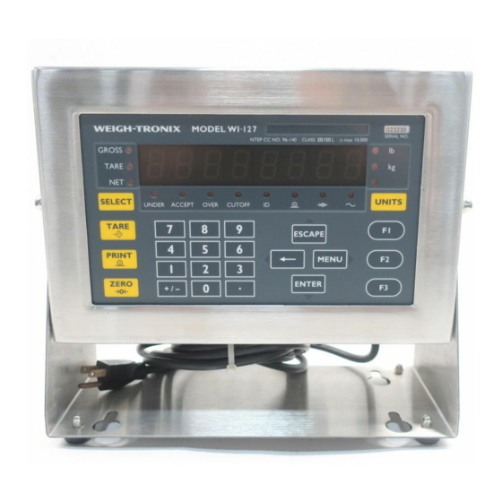
Avery Weigh-Tronix WI-127 Service Manual
Digital weight indicator
Hide thumbs
Also See for WI-127:
- User manual (23 pages) ,
- Installation manual (8 pages) ,
- User manual (20 pages)
Table of Contents
Advertisement
Advertisement
Table of Contents

Related Manuals for Avery Weigh-Tronix WI-127


Summary of Contents for Avery Weigh-Tronix WI-127
- Page 1 WI-127 Indicator Service Manual...
-
Page 2: Table Of Contents
Creating Layouts ....................... 51 Creating Groups ....................... 54 Broadcast ..........................55 Autosend ..........................55 Using Inputs and Outputs on the WI-127 ..................56 WI-127 Disassembly and Reassembly ....................57 Installing Option Cards ......................... 58 Inbound/Outbound (GTN) Software ..................59-74 In-Motion Software ......................... 75-86 Technical Illustrations .......................... -
Page 3: Specifications
WI-127 Specifications* Power requirements: Standard outputs: 115 Volts AC, +10% to -15% @ 0.3Amp maximum Three outputs, open collector design 230 Volts AC, +10% to -15% @ 0.15 AMP maximum Relay power supply, 24 VDC at 150mA 50 /60 Hz... -
Page 4: Introduction
Introduction This manual covers the service issues for the WI-127 indicator. The manual is divided into the following sections: • Introduction When installing the WI-127, the • Error Messages power socket-outlet must be nearby • Service Menu Structure and easily accessible. -
Page 5: Service Menu Structure
Default is 2 seconds. This can also apply to optional 2nd and 3rd serial ports. Service Menu Structure You configure, calibrate and do testing of the WI-127 using a menu structure Moving Through Menus which you move through using directional keys on the front panel. The directional... -
Page 6: Accessing The Menu
ESCAPE key for two seconds. If you do not know the password Do not break any seal on the you may remove the nylon plug on the back of the WI-127 and press the SEAL indicator unless absolutely necessary. -
Page 7: Using The Service Menu
Using the Service Menu Figures 2 through 19 show the service menu structure in the WI-127. Following each figure are explanations for each of the service menu items. The complete service menu structure can be viewed on the last fold out pages in the back of this manual. -
Page 8: Audit Menu
Audit menu Figure 4 Audit menu These are the items listed in the Audit menu: Cal. 0000 This is an example of how the calibration audit trail counter will appear. The actual value will be between 0000 and 9999. It is nonresettable and may not be edited. -
Page 9: Test Menu
T est Menu Figure 5 shows the Test menu. Use this menu to check functions of the WI-127. The description of each menu item follows Figure 5. Figure 5 Test menu These are the items listed in the Test menu from left to right:... - Page 10 Loop - No Loop test. Connect the transmit line to the receive line at some point in the cabling. The WI-127 checks if it receives the same characters that it transmits. If it can, LOOP is displayed. If it cannot, no LOOP is displayed.
-
Page 11: Setup Menu
The two top level menu items under Setup are 110 and 127. This selection allows access to the menus necessary to make the WI-127 behave as a clone of the WI-110 indicator. This selection allows all setup menus to be accessed. -
Page 12: Top Level Of 110 Menu
Top Level of 110 Menu The top level menu items of the 110 menu are shown in Figure 7. Figure 7 110 Menu Adjust Use this submenu for calibration of the scale. To exit back to normal weighing Scale Use this submenu for configuring units, capacity, divisions, zero, mode, press the SELECT key and stability, A.Z.T., update rate, averaging and filtering. - Page 13 See the section Calibrating the WI-127 for indepth instructions. In this submenu you may view, edit, insert or delete calibration points in a list. The WI-127 allows calibration using up to five calibration points. The WI-127 comes from the factory with two calibration points: 0 and 5000 lbs.
-
Page 14: Scale Menu
110 Scale Menu The next item in the 110 menu structure is Scale. In this group of submenus you set scale related parameters. Figure 9 shows the Scale menu. Figure 9 110 Scale menu Units This submenu lets you select what unit of measure will be assigned to the three annunciators on the front panel. - Page 15 Capacity The next scale menu item is capacity. Use this item to view or Don’t forget to re-calibrate your edit the capacity of the unit in any unit of measure configured system after you change capacity. under Units. With CAPACity displayed, press the key.
- Page 16 Average The next menu item is Average. This can be entered in one of two methods: x disp. or x a-ds. Press the UNITS key to switch back and forth between the two choices. The suggested method of setting the average is by picking a value for x disp.
-
Page 17: Tips On Setting Up And Using The Harmonizer Filtering
® Tips on setting up and using the Harmonizer filtering To find the best settings for your filter needs, follow the steps listed below. 1. What to Do: Determine the amount of positive and negative force exerted by the vibration on the scale. How to Do It: Set Threshld to 0.0, Constant to OFF, and Average to 1.0 A-Ds. -
Page 18: Options Menu
110 Options Menu The third item in the 110 menu structure is Options. Figure 10 shows the Options Menu. Use this menu to enable/disable and configure the buttons on the front panel. Figure 10 110 Options menu Select Enables or disabled the SELECT key. Units Enables or disables the UNITS key. -
Page 19: Serial Menu
Print PB Print This item determines which layouts are sent to which ports for pushbutton print. Press and Group is displayed. From this item you may either disable the pushbutton print option, or select a group to print. To select a group, press again. - Page 20 Port 1, 2 & 3 Ports 2 and 3 present if optional Port 1 is the onboard serial port. Any additional boards installed hardware is installed. are configured under Ports 2 & 3. Ports 2 & 3 show up in the Serial Menu only if additional boards are installed.
-
Page 21: Seal Menu
110 Seal Menu The last item in the 110 Setup menu is Seal. Use this submenu to set up a custom password and to set the sealing choices for the unit. Items in the Setup menu (Figure 6) can be protected from unrecorded changes. Two internal counters record changes to items in the Setup menu. - Page 22 If Phys. is set to Yes, you must remove the physical seal (rear sealing plug) of the WI-127 to access an internal switch. When you press this switch you have full editing privileges and the display shows the first item in the Service menu, About, without the need to enter the password.
-
Page 23: Top Level Of 127 Menu
Seal Use this submenu to setup a custom password and to set the sealing choices for the unit. Transfer Use this submenu to setup the WI-127 to receive or send print formats from the WI-127 downloader software package in your... -
Page 24: Adjust Menu
See the section Calibrating the WI-127 for indepth instructions. In this submenu you may view, edit, insert or delete calibration points in a list. The WI-127 allows calibration using up to five Press the ZERO key to delete a calibration points. -
Page 25: Scale Menu
127 Scale Menu The next item in the 127 menu structure is Scale. In this group of submenus you set scale related parameters. Figure 15 shows the Scale menu. Figure 15 127 Scale menu Units This submenu lets you select what unit of measure will be assigned to the three annunciators on the front panel. - Page 26 Example 1: To create a ‘stone’ unit of measure, the Basis would be 14 pounds and Equals should be 1 stone. Example 2: To create an ounce unit of measure, the Basis would be 1 pound and Equals should be 16 ounces.
- Page 27 If you change capacity or division Division This selection allows you to view and edit the division size of the size in any unit of measure, this enabled units of measure. You can enter any division size. The automatically changes all the other indicator will use the closest division size for each enabled unit of enabled units of measure as well.
- Page 28 Average The next menu item is Average. This can be entered in one of two methods: x disp. or x a-ds. Press the UNITS key to switch back and forth between the two choices. The suggested method of setting the average is by picking a value for x disp.
-
Page 29: Tips On Setting Up And Using The Harmonizer Filtering
® Tips on setting up and using the Harmonizer filtering To find the best settings for your filter needs, follow the steps listed below. 1. What to Do: Determine the amount of positive and negative force exerted by the vibration on the scale. How to Do It: Set Threshld to 0.0, Constant to OFF, and Average to 1.0 A-Ds. -
Page 30: Options Menu
127 Options Menu The third item in the 127 menu structure is Options. Figure 16 below shows the Options Menu. Use this menu to configure the keys on the front panel as well as define print layouts. Figure 16 127 Options Menu... - Page 31 Enables or disables the F3 key. The default setting for this key accesses the cutoff values. Display The Display submenu allows you to customize the order in which the WI-127 cycles through its weight display modes and units of measure. If Net is removed from Select mode, Select Customize the list of weight display modes here.
- Page 32 ASCII strings, create groups and enable continuous send. ASCII The WI-127 can store up to sixteen ASCII strings, each contain- ing up to 32 individual ASCII characters. The WI-127 contains one default ASCII string. You may customize this string as well as build fifteen additional ones.
- Page 33 Under the selected input, under Ch (Channel), choose an ASCII character, for example Z, represented by decimal value 90. See Table 5 in the WI-127 Service Manual for a complete list of ASCII charac- ters. Go over from Ch to Action. Under Action drop down and select Zero from the menu choices.
-
Page 34: Serial Menu
Serial Menu only if additional boards are installed. Busy Enables or disables the ready/busy input. If the ready/busy input By default the WI-127 ports accept is enabled, you may enter a timeout period. This value deter- an enquire (ENQ) (05) character. If... -
Page 35: Bcd Out Menu
127 BCD Out Menu The next item in the 127 menu structure is B.C.D. Out. Figure 19 below shows this menu. This submenu configures what the BCD output board will print. It is offered only if the BCD board is installed. Choices are: off, displayed weight, gross weight, and net weight. -
Page 36: Outputs Menu
The zero adjustment has a +/- 10% range, 90.000 to 110.000 on the display. Weight does not have to be on the scale to perform this task. This submenu, shown in Figure 20, is where you configure the WI-127’s outputs. 127 Outputs Menu Update Choose an update display rate for the cutoffs. -
Page 37: Inputs Menu
127 Inputs Menu Use this submenu, shown in Figure 20a, to assign actions to the onboard hardware inputs. The action for each input is selectable from this list: Print; Reply; Zero; None; Units; Unit 1; Unit 2; Unit 3; Select; Gross; Net; Tare; P.B. Tare. See the explanations for each of these at the bottom of the page. -
Page 38: Seal Menu
127 Seal Menu The next item in the 127 Setup menu is Seal. Use this submenu to set up a custom password and to set the sealing choices for the unit. The Seal Menu is shown in Figure 21. Figure 21 127 Seal Menu Items in the Setup menu (Figure 6) can be protected from unrecorded changes. -
Page 39: Transfer Menu
Calibration and Configuration list 127 Transfer Menu Use this submenu to setup the WI-127 to receive or send print formats from the WI-127 downloader software package in your PC. See Figure 21. This is the end of the 127 section. -
Page 40: Reset Menu / Master Clear
Reset Menu / Master Clear The reset menu shown in Figure 23 appears in two cases. User Master Clear as a last resort before sending in the If you do a Master Clear (powering up the unit with both the MENU and unit for repair. -
Page 41: Calibrating The Wi-127
Standard calibration generally uses two calibration points; for linearization, more than two may be used. The WI-127 comes from the factory with two calibration points: 0 and 5000 lbs. (These weight values may differ depending on your unit of measure.) To perform linearization, you can insert more calibration points (up to a total of five points). -
Page 42: Weight Calibration
Weight Calibration To calibrate your scale using live weight calibration, follow these steps: With PointS displayed, press . . . 0 is displayed. This is the zero calibration point. To view or edit the weight in another To calibrate your scale’s zero configured unit of measure, press point, press . -
Page 43: Count Calibration
Count Calibration To calibrate your scale using count calibration, follow these steps: With PointS displayed, press . . . 0 is displayed. This is the zero calibration point. To view or edit the weight in another configured unit of measure, press Press . -
Page 44: Adding Calibration Points
You may add these points at the same time you are calibrating the Points zero load and full capacity points. Points do not have to be inserted in the correct order. The WI-127 will automatically order the points based on count values. To add linearization points: With A XXXX displayed, press +/- . - Page 45 Press . . . CAL. is displayed. Press . . . CountS is displayed. Press again. . . dELEtE is displayed. Press . . . no is displayed. Press . . . yES is displayed. Press . . . The point is deleted and A XXXX (next calibration point) is displayed.
-
Page 46: Customizing The Serial Output
Customizing the Serial Output The WI-127 has sixteen available print layouts. Nine have default settings. Ex- Predefined amples of the nine default layouts are shown below in printout form. Their actual Print Layouts layout codes are shown on the following pages. - Page 47 Just as in other Weigh-Tronix indicators (WI-125, WI-150, etc.) the layouts within the WI-127 may be customized. If the nine default layouts do not fit your specific applications, or if you wish to include, for example, custom wording, you may...
- Page 48 Listed below are the predefined print layouts. You may customize these, or create up to seven new layouts. Layout 1 Layout 2 Layout 3 Layout 4 Layout 5 Layout 6 Layout 7 Anyplace you see in a layout at right, you will actually see on your indicator.
-
Page 49: Ascii Strings
ASCII codes are simply numbers (code values) a computer can translate into letters, numbers and actions. The WI-127 can store up to sixteen ASCII strings, each containing up to 32 individual characters. These strings are numbered 1-16. Below is a worksheet to help define several ASCII strings. - Page 50 Table 5 ASCII Control Code Values N O T E N O T E N O T E: To repeat a control code a number of times, enter the control code #, a decimal, then the number of times you N O T E N O T E want it repeated.
-
Page 51: Step By Step Instructions
1 2 7). . . The code number is displayed. 2a. Press and hold two seconds. . . About is displayed. 2b. Press the SEAL switch inside the WI-127. . . About is displayed. Press . . . SEtUP is displayed. Press . -
Page 52: Creating Ascii Strings
It is within the ASCII submenu that you create/customize the ASCII strings to be Creating ASCII strings used in your layouts. Label This item allows you to edit the gross, net, tare, and ID labels. With LAbEL displayed, press . . . GroSS is displayed. - Page 53 Strings This item allows the creation of up to sixteen different ASCII strings. On a new indicator, there is one default ASCII string. You may edit the existing string as well as create up to fifteen more. Viewing strings With StringS displayed, press .
-
Page 54: Creating Layouts
The WI-127 allows the creation of up to sixteen different layouts. A new indicator contains nine default layouts. You may edit any or all of these nine, or create seven additional, new layouts. - Page 55 Press . . . LAY. 02 is displayed. On a new indica- tor, the nine default layouts are present. You may create up to seven more. Repeat steps 1-5 above to view all the layouts. With LAYOutS displayed, Creating new layouts press .
- Page 56 Editing layouts There are two keys to remember when inserting or deleting items in a layout: +/- will insert and ZERO will delete. We will use the following example to illustrate how to edit layouts: remove and then replace the line feed from default layout 01.
-
Page 57: Creating Groups
Creating Groups A group is the combination of your layout and the assigned serial port through which the data is sent. The Groups submenu is where you specify which ports will print which layouts. A total of nine groups is available. Within each group, up to three ports can output layouts. -
Page 58: Broadcast
Press . . . YES is displayed. 10. a. If you wish to inhibit the printout when motion is detected, press . . . Yes is selected and Inhibit is displayed. b. If you do not wish to inhibit the printout when motion is detected, press , then... -
Page 59: Using Inputs And Outputs On The Wi-127
Using Inputs and Outputs on the WI-127 Input Connection Action Standard Inputs (defaults shown) TB15-2 Remote Zero Key TB15-3 Remote Print Key TB15-4 Go to Net Mode The inputs are configurable. See 127 TB15-5 Go to Gross Mode Inputs Menu section. -
Page 60: Disassembly And Reassembly
Follow the instructions in this section to disassemble the WI-127. Unplug the WI-127 from the power source. Remove the back of the WI-127 by removing the sixteen acorn nuts and pulling the back cover from the case. See Figure 25. -
Page 61: Installing Option Cards
Installing Option Cards Follow the disassembly instructions on previous page. Option cards plug into J19 or J20 on the mother board. Remove the four hold-down screws shown in Figure 27 for J19 or J20. Install the standoffs in these holes and plug in the option card. When serial boards are installed in Attach the option card to the standoffs with the screws. -
Page 62: Inbound/Outbound (Gtn) Software
WI-127 Inbound/Outbound Software This section of the WI-127 Service manual covers the optional inbound/outbound software. This software has the following additions made to the service menus. The complete service menus are included at the end of this section. Below are descriptions of each additional item. - Page 63 The WI-127 Inbound/Outbound indicator has a total of 32 available print layouts. These layouts replace the sixteen found in the standard WI-127.
- Page 64 Layout # 28: Inbound/Outbound Report Layout 12 Layout 17 Layout 21 Layout 21 Layout 21 Layout 21 Layout 21 Layout 18 Layout 22 Layout # 27: Stored Tare Transaction Layout 12 Layout 13 Layout 14 Layout 15 Layout 16 Layout # 29: Stored Tare Report Layout 12 Layout 19 Layout 23...
- Page 65 Below are the actual layout codes for the 29 predefined layouts. They are num- Predefined layouts bered in the same order in which they are available in the indicator. Layout 1 Layout 2 Layout 3 Layout 4 Layout 5 Layout 6 Layout 7 Layout 8 Layout 9...
- Page 66 Layout 15 Layout 16 Layout 17 Layout 18 Layout 19 Layout 20 Layout 21 Layout 22 Layout 23 Layout 24 Layout 25 Layout 26 Layout 27 Layout 28 Layout 29...
- Page 67 Following are 16 print items which have been added to the WI-127 Inbound/Outbound indicator. The standard WI-127 has 19 items. Adding these 16, you will have a total of 35 items with which to build print layouts.These items are found in the “Layouts”...
- Page 68 The WI-127 Inbound/Outbound can store up to sixteen ASCII strings, each containing up to 32 individuals characters. These strings are numbered 1-16. The WI-127 Inbound/Outbound contains 15 default ASCII strings. Below is a table containing the 15 default strings. Use these, or develop your own custom mes-...
- Page 69 Printing Groups In order to print, the layouts in the WI-127 are assigned to groups. These groups are in turn assigned to specific serial ports. A group may contain several layouts or only one layout. Each group can have up to three serial ports. Each port can have a different layout assigned to it.
- Page 70 Reset Menu An additional parameter is added to the Inbound/Outbound Reset Menu. Database This parameter will flash if the database is corrupted. This parameter is not visible if there are no entered records. Will not reset database to default values. Will reset database to default values.
- Page 72 Defaults: Descending lines intersect the default values for each item.
-
Page 78: In-Motion Software
WI-127 In-Motion Software This section of the WI-127 Service manual covers the optional in-motion software for Conveyor/Monorail scales. This software has the following additions made to the service menus. The complete service menus are included at the end of this section. - Page 79 Filter/Threshold Filter constant = 3 100 lb (The filter threshold should be set at the configured capacity as a minumum.) Options Define Autosend Group 1 (Displayed Weight) Buttons Print/P.B. Print Group 1 (Displayed Weight) Autoprint While in the in-motion mode, autoprint changes functionality to automatically print each time an in-motion weighment is made through the in-motion logic.
- Page 80 Tare Registers - View/Edit the 10 tare registers. Over - View/edit the over register. Under - View/edit the under register. Target - View/edit the target register. Cutoffs - View/edit the cutoff registers. New Layout Items Label Averaged Outputs an ASCII string defined to represent the status of the Selected weight, Averaged or Live.
- Page 81 (1) above. WI-127 to Conveyor and Monorail Wiring Information The wiring information to connect a WI-127 indicator to a CVC/CVCS conveyor scale or in-motion monorail scale is as follows:...
- Page 82 In-Motion Conveyor Miscellaneous Information The WI-127 would need to have the special in-motion software installed to be compatible with the CVC operation. The recommended filter settings for the in- motion operation is a Filter time constant of 3 and a threshold equal to full scale capacity.
-
Page 90: Technical Illustrations
WI-127 INDICATOR (115/230VAC) PARTS AND ASSEMBLY ITEM DESCRIPTION W-T P/N Enclosure,SST 49057-0017 Bezel Gasket 49061-0011 Keypad / Backer Plate Assy (standard) 49060-0012 Keypad / Backer Plate Assy (GTN) 49060-0038 Main Pc Board Assy (115VAC) 49067-0015 Main Pc Board Assy (230VAC) - Page 91 WI-127 INDICATOR (115/230VAC) SYSTEM BLOCK DIAGRAM...
- Page 92 WI-127 INDICATOR (115/230VAC) MAIN PC BOARD P/N 49067-0015 (115VAC) P/N 49067-0023 (230VAC) EXCITATION CHART NOTE: P6 Jumper Typ. Exc When using barriers, the two pin jumper is not Position Voltage connected and should be stored on pin-1. The barrier should drop the excitation voltage down typical 3-4 10.0...
- Page 93 WI-127 INDICATOR (115/230VAC) OPTION BOARDS ANALOG OUTPUT SERIAL IO SERIAL PORT # 2 or 3 JUMPER POSITION TYPE RS-232 1 - 2 ------- ------- RS-422 ------- 1 - 2 ------- RS-485 ------- 1 - 2 ------- current ------- ------- 1 - 2...
- Page 94 WI-127 INDICATOR (115/230VAC) OPTION BOARDS CUTOFF & INPUT BCD PARALLEL...
- Page 95 WI-127 INDICATOR (115/230VAC) KEYPAD OVERLAY P/N49058-0016 (STANDARD) KEYPAD OVERLAY P/N49058-0024 (GTN) MATRIX...
- Page 96 WI-127 INDICATOR (115/230VAC) OPTION BOARD PROCEDURE INSTALLATION ITEM DESCRIPTION W-T P/N Nut, Kep, #6-32 1025-00114 4/board ---- NO PART ---- Standoff, m/f, 6-32 x .56L 15437-5000 4/board Screw, Sem, #6-32 x .25L 1006-02600 4/board Analog Output Power Cable Assy 49375-0053 Analog Output pc.
- Page 97 WI-127 INDICATOR (115/230VAC) WALL MOUNT OUTLINE DRAWING...
- Page 98 WI-127 INDICATOR (115/230VAC) PANEL MOUNT OUTLINE DRAWING...
- Page 102 Weigh-Tronix 1000 Armstrong Dr. Fairmont, MN 56031 USA Telephone: 507-238-4461 Facsimile: 507-238-4195 e-mail: industrial@weigh-tronix.com www.weigh-tronix.com Weigh-Tronix Canada, ULC 217 Brunswick Blvd. Pointe Claire, QC H9R 4R7 Canada Telephone: 514-695-0380 Facsimile: 514-695-6820 Weighing Products & Systems Weigh Bar ® is a registered trademark of Weigh-Tronix Inc. 04/13/00 127SERVC.P65 PN 29633-0012e1 Printed in USA...
Need help?
Do you have a question about the WI-127 and is the answer not in the manual?
Questions and answers