Zapi SMART CONSOLE User Manual
Hide thumbs
Also See for SMART CONSOLE:
- Manual (11 pages) ,
- Instructions manual (8 pages) ,
- Instructions (5 pages)
Table of Contents

Related Manuals for Zapi SMART CONSOLE


Summary of Contents for Zapi SMART CONSOLE
- Page 1 ELECTRONIC • OLEODYNAMIC • INDUSTRIAL EQUIPMENTS CONSTRUCTION Via Parma, 59 – 42028 – POVIGLIO (RE) – ITALY Tel +39 0522 960050 (r.a.) – Fax +39 0522 960259 e-mail: zapi@zapispa.it – web: www.zapispa.it User Manual SMART CONSOLE...
- Page 2 Under no circumstances will Zapi S.p.A. be held responsible to third parties for damage caused by the improper use of the present publication and of the device/devices described in it. Zapi spa reserves the right to make changes or improvements to its products at any time and without notice.
-
Page 3: Table Of Contents
CANBUS connection and external supply ............ 9 2.4 Supported products ....................9 2.4.1 CAN communication ..................9 2.4.2 Serial communication .................. 10 2.5 Update of SMART Console firmware ................ 11 3 QUICK START ........................12 3.1 How it looks ......................12 3.1.1 The display ....................12 ... - Page 4 PERIODIC MAINTENANCE TO BE REPEATED AT TIMES INDICATED ......50 APPROVAL SIGNS COMPANY FUNCTION INITIALS SIGN PROJECT MANAGER TECHNICAL ELECTRONIC MANAGER VISA SALES MANAGER VISA Publication N°: AFGZP0BA Edition: October 2014 Page - 4/50 AFGZP0BA – SMART CONSOLE - User Manual...
-
Page 5: Introduction
CAN messages to a USB memory stick. This manual will detail all characteristics of the Smart Console. For new customer willing to test the Smart Console as much quickly as possible a dedicated chapter is available: see Chapter 3 “Quick Start”. -
Page 6: Overview
Silicone keyboard resistant to industrial environment Key placement to navigate easily through console menu Communication through: o Current-loop serial line as standard Zapi console o CANBUS line CAN speed up to 500kpbs CAN protocols supported:... - Page 7 Absolute voltage range on CNX6 (CANL) and CNX7 Respect to -80÷80V (CANH) ground During CNX6 (CANL) output voltage 0÷2V communication During CNX7 (CANH) output voltage 3÷5V communication Maximum CAN speed 500kbps AFGZP0BA - SMART CONSOLE - User Manual Page - 7/50...
-
Page 8: Environmental
Operational temperature: -10°C ÷ 50 °C 2.3 Operational Modes The Smart Console has been designed to have multiple ways of operation. Three modes can be identified: Serial connection powered by four standard AA size batteries placed in the ... -
Page 9: Canbus Connection And Internal Supply
2.3.2 CANBUS connection and internal supply The Smart Console can connect to an existing CAN line and connect with any Zapi controller inside this line. Operation is similar to the PC CAN Console software but it is not needed to have a Personal Computer. -
Page 10: Serial Communication
Smart Console has no isolated CAN transceiver but it is possible to connect to this type of line in two ways: Use internal batteries. In this case connect NCAN to the ground of the console: don’t connect any other ground signal from the application! CAN communication will run normally ... -
Page 11: Update Of Smart Console Firmware
“custom” serial protocol. Contact Zapi for support. 2.5 Update of SMART Console firmware The firmware installed in the Smart Console can be modified if needed. There are many reasons behind the need to update the firmware: ... -
Page 12: Quick Start
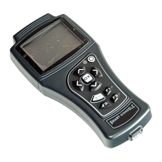
3.1.1 The display A bright 3.2’’ TFT LCD display is the core of the console. Every time it turns on it will display first the Zapi logo and then the HOME SCREEN. Majority of menus has a simple colour palette with white text on black background. -
Page 13: The Main Connector
3.1.3 The Main connector The main connector is placed in the top part of the Smart Console. It is a 15 pin D-subminiature (DA-15) female connector. The main connector is called CNX in this manual. When referring to a single pin “k”, the name CNXk will be used... - Page 14 Smaller voltages will prevent console starting. PLACING BATTERIES 1. With Smart Console turned off, open the battery holder by removing its cover. Notice that this operation exposes part of the electronic board: do this operation while in a clean environment! 2.
- Page 15 The console can be turned on with or without the cable already inserted. 1) Press ON key and keep it pressed. The Smart Console will turn on. 2) Notice that the led is off and it remains off for about three second even if the console is booting.
-
Page 16: Serial Connection (Internal Aa Batteries)
3.3 Serial connection (internal AA batteries) The use of the Smart Console with serial connection is very similar to the use of the Console Ultra. CONNECT THE CONSOLE To connect the Smart Console to the target, it is required to have a CNX-to- Molex SPOX cable. - Page 17 First line tells the controller firmware Second line shows controller voltage, controller current and hourmeter Last line shows the current alarm code, if present Press OK to access the MAIN MENU AFGZP0BA - SMART CONSOLE - User Manual Page - 17/50...
- Page 18 You can press ESC to exit the menu at any time. In case some parameter has been modified, the console will prompt a request to confirm/discard changes. Page - 18/50 AFGZP0BA – SMART CONSOLE - User Manual...
- Page 19 It is possible to “block” a variable so that it remains displayed during scrolling. Once the desired variable is highlighted press RIGHT: it will be highlighted in a different colour. AFGZP0BA - SMART CONSOLE - User Manual Page - 19/50...
- Page 20 Press ESC to go back to MAIN MENU. Notice that pressing F1 will activate graphical representation over time of the selected variables Graphic tester feature isn’t fully operative yet: it will be activated in a future firmware. Page - 20/50 AFGZP0BA – SMART CONSOLE - User Manual...
- Page 21 Press F1 to cancel the alarm logbook of the controller: once pressed, the console will ask for confirmation. PROGRAM VACC Program VACC menu has been slightly modified compared with old console. Upon entering this menu the console will show the current programmed values. AFGZP0BA - SMART CONSOLE - User Manual Page - 21/50...
- Page 22 To end connection, just return to the HOME SCREEN: at this point it is possible to remove the cable from the target controller. If cable is removed while it is inside other menu, the console will return a NO COMMUNICATION alarm. Page - 22/50 AFGZP0BA – SMART CONSOLE - User Manual...
-
Page 23: Can Connection (Internal Aa Batteries)
Smart Console is able to connect to Zapi controllers inside a CAN line. Operation is very similar to the CAN CONSOLE software for PC: any controller will be able to communicate with Smart Console if it can communicate with that PC tool. - Page 24 In case the smart console must operate from external supply, a forth signal is necessary: a valid power supply must be connected to pin CNX8. This guide supposes console is running from internal batteries. See 3.5 if an external supply is used.
- Page 25 The operator shall choose the type of protocol and the baud rate. The Autoscan function support two types of protocol: 1. Zapi Standard protocol: mainly found in application where all nodes are Zapi products 2. Zapi CANOPEN protocol: more common when CAN node are both Zapi products and third-party ones.
- Page 26 When OK is pressed the Smart Console will scan the CAN line looking for valid CAN nodes. Scanning operation is about 5 second long. After scan is complete, the list of nodes will be shown (if found). Some node will have a “*”...
-
Page 27: Can Connection (External Supply)
4) As soon as voltage is available at CNX8 the Smart Console will turn on and HOME SCREEN will appear. From this point on, console can be used according to section 3.4. -
Page 28: Hardware Layout
Mechanical shocks can create cracks and fissures in the cover. The mechanical shock can propagate inside the product causing cracks in the electronic board and displacement of components. Do not use a console with a damaged cover! Page - 28/50 AFGZP0BA – SMART CONSOLE - User Manual... - Page 29 AFGZP0BA - SMART CONSOLE - User Manual Page - 29/50...
-
Page 30: Cnx Connector
DA-15 connector has been chosen because it is widely available on the market. Even if Zapi is always available to design custom cables, the customer is encouraged to create its own cables depending on its need. -
Page 31: Cables
Do not connect. For future use. 4.3 Cables 4.3.1 Serial cable The Smart Console is shipped with a cable for connecting all Zapi products which have the serial line The connector at the controller-side is the same Molex SPOX type as the old Console Ultra. - Page 32 Page - 32/50 AFGZP0BA – SMART CONSOLE - User Manual...
-
Page 33: Can Cable And Connector
There is no specific CAN connector: CAN signals can go through any type of suitable connector. Each customer must choose the best way to connect the Smart Console to its truck: a dedicated connector, placed somewhere inside the truck, is the best solution. -
Page 34: Keyboard
This section will describe them all. Console turned on A fixed active led indicate the Smart Console is running. In some cases the led can blink (see below). The led is never off with console turned on and operating correctly. If the led goes off a failure must have happened. -
Page 35: On Button
To power off, press ON button for some second ON button can be used to reset the Smart Console in case it is stuck or it does not respond correctly to commands. Keep the button pressed and it will turn off. -
Page 36: Usb And Console Supply Source
To improve use, the USB socket is readily accessible and not protected by covers against dust and other environmental factors: be careful while handling the console and avoid contamination by external agents. Page - 36/50 AFGZP0BA – SMART CONSOLE - User Manual... -
Page 37: Special Functions
Test of different truck configuration 5.1 DOWNLOAD PARAMETER LIST TO USB STICK When Smart Console is connected to a controller, it has the possibility to download all parameters inside a USB stick. To use this function, enter the menu SAVE PARAMETER USB in the MAIN MENU. - Page 38 Connect the USB stick to a PC and enter the directory of point 1). There will be a subdirectory with the correct name and, inside this one, a csv file will be present. Page - 38/50 AFGZP0BA – SMART CONSOLE - User Manual...
-
Page 39: Datalog Of Can Traffic
Don’t remove USB stick during download or the file will be empty or corrupted! 5.2 DATALOG OF CAN TRAFFIC The Smart Console can save all CAN messages inside the USB stick. Notice that messages are saved as they are, without any post-processing. Obviously this function is unavailable when serial line is used. -
Page 40: Download Procedure
The display will show: Only baud rate must be specified before starting. Press OK to start: at this point Smart Console will check the presence of the USB stick. If it is absent display will ask operator to insert one in the USB socket. As soon as it is plugged, data-logging will start automatically. -
Page 41: Graphical Tester
Use this function when console seems stuck or it does not respond properly to commands. Notice that interrupting any function which was operating with USB will likely cause the corruption of the output file. AFGZP0BA - SMART CONSOLE - User Manual Page - 41/50... -
Page 42: Menu Console
It defines the preferred speed of the serial connection. Default value is 9600bps and it should be modified rarely. Larger speeds will improve reactivity of console when connected to recent Zapi products. On the contrary older controller may fail the connection handshake or they may exhibit disconnections. -
Page 43: Read Ram And Read Eeprom
Alkaline if non-rechargeable batteries are used. 6.2 Read Ram and Read Eeprom As for any other Zapi product it is possible to access memory cells inside the RAM or inside the EEPROM of the console. Select the menu to use depending on which memory cell must be read/written. -
Page 44: Password Management
Smart Console is already shipped with correct time and date. Factory setting uses CET standard time. It is equivalent to UTC+1 (UTC+2 in summer time) Button cell should last for many years. If RTC loses its setting, the cell must be replaced. - Page 45 Password is 5-digit long and it must be numerical. Default password is 00000. Be careful: new password is inserted without hiding digits and it is not requested twice before confirmation. AFGZP0BA - SMART CONSOLE - User Manual Page - 45/50...
-
Page 46: Alarms And Icons
7 ALARMS AND ICONS Smart console has few alarms and warnings. This chapter lists them all. Due to limited display space, these alarms are visualized according to a priority list: 1. Lowest priority: read-only mode 2. Middle priority: battery low indication 3. -
Page 47: Alarms
Troubleshooting: restart the console. If it happens continuously, contact Zapi for assistance. 7.3.2 EEPROM KO alarm Smart console has an internal EEPROM for its own parameters and to carry out the SAVE/RESTORE functions. The content of the EEPROM is checked at each starting to detect data corruption. - Page 48 Troubleshooting: switch off the console immediately! Check the cable for wrong connections. If internal batteries have been used, check their voltage. If the problem persists, contact Zapi. Page - 48/50 AFGZP0BA – SMART CONSOLE - User Manual...
-
Page 49: Acknowledgments
Licensed under the Apache License, Version 2.0 (the "License") Apache License Version 2.0, January 2004 http://www.apache.org/licenses/ http://developer.android.com/design/style/typography.html MICROSOFT EXCEL Microsoft Excel is a registered trademark of Microsoft Corporation in the United States and/or other countries AFGZP0BA - SMART CONSOLE - User Manual Page - 49/50... -
Page 50: Periodic Maintenance To Be Repeated At Times Indicated
The connection of the console should be made according to the description included in this Manual. Any variations or special requirements should be made after consulting a Zapi Agent. The supplier is not responsible for any problem that arises from wiring methods that differ from information included in this Manual.
Need help?
Do you have a question about the SMART CONSOLE and is the answer not in the manual?
Questions and answers