Advertisement
Quick Links
CONFIDENTIAL INFORMATION
OF BASLER ELECTRIC COMPANY, HIGHLAND, IL.
IT IS LOANED FOR CONFIDENTIAL USE, SUBJECT
TO RETURN ON REQUEST, AND WITH THE
MUTUAL UNDERSTANDING THAT IT WILL NOT BE
USED IN ANY MANNER DETRIMENTAL TO THE
INTEREST OF BASLER ELECTRIC COMPANY.
WARNING
To prevent personal injury or equipment
damage, only qualified
operators should install, operate, or
service this device.
ELECTRICAL SPECIFICATIONS
Dc Output Power:
4
Adc
at
63
Vdc
(252W)
continuous,
7 Adc at 100 Vdc (700W) forcing one minute
(at 240 Vac input).
Exciter Field Dc Resistance:
15 ohms minimum; 100 ohms maximum.
Ac Power Input:
Operating range: 190 Vac to 240 Vac, +10%,
Single phase, 50/60 Hz +5%, Burden 500 VA.
Voltage Adjust Range:
171-264 Vac.
Regulation Accuracy:
Better than ±1.0% no load to full load.
Response Time:
Less than 1.5 cycles for +10% change in
sensing voltage.
EMI Suppression:
Internal electromagnetic interference filter
(EMI filter).
Overexcitation Shutdown:
Output power is removed under the following
conditions: Exciter field voltage exceeds
100+5 Vdc for a time inversely proportional to
voltage magnitude, or instantaneously if the
exciter field voltage exceeds 135+5 Vdc.
Voltage Build-up:
Internal provisions for automatic voltage build-
up from generator residual voltages as low as
10 Vac.
Power Dissipation:
8 Watts maximum.
PHYSICAL SPECIFICATIONS
Operating Temperature:
-40° C (-40° F) to +60° C (+140° F).
Storage Temperature:
-65° C (-85° F) to +85° C (+185° F).
CSA Approved
FUSES
It is recommended that fuses with high
interruption capability be installed per the
interconnection diagram to protect wiring from
faults before the regulator.
Interconnection Diagram.
NOTE
Fuse
must
be
installed
interconnection diagrams to avoid inter-
rupting the field current.
CALL US TODAY
CALL US TODAY
1-888-POWER-58
1-888-POWER-58
INSTRUCTION MANUAL
VOLTAGE REGULATOR
MOUNTING
The regulator may be mounted in any
technicians or
position. Refer to the drilling diagrams.
maximum
EXCITER FIELD POWER CIRCUIT (wires F+
and F-).
Connect the regulator wire F+ to the brushless
exciter field terminal F+, and wire F- to
terminal F-.
The dc resistance of the exciter field
must be equal to or greater than 15 ohms
and less than 100 ohms.
POWER/SENSING INPUT CIRCUIT (wires 3
and 4)
Connect as shown by the Interconnection
Diagram.
UNDERFREQUENCY CHARACTERISTIC
POINT
For 50 Hz systems, connect the Hz leads.
For 60 Hz systems, disconnect the Hz leads.
See curves the following figure.
Refer to the
per
the
FOR
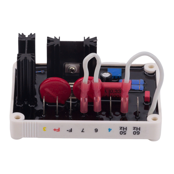
Model: VR63-4B
Drilling Diagram
CAUTION
REQUEST A QUOTE
REQUEST A QUOTE
parts@genpowerusa.com
parts@genpowerusa.com
Publication:
9 1668 00 996
© 1998, Basler Electric Co., Highland, IL 62249
First Printing August 1988
Revision: C
ECA: 16515
Frequency Compensation Curves
OVEREXCITATION SHUTDOWN
This circuit removes the output power if the
exciter field voltage exceeds 100 ±5 Vdc after
a time delay. If the voltage exceeds, 135 +5
Vdc,
the
output
power
is
instantaneously.
After
shutdown,
reset
the
regulator
decreasing voltage below 6 Vac either by
stopping the prime mover or interrupting the
regulator input with a reset switch for 2
seconds or more.
VOLTAGE ADJUST
Screwdriver adjustable potentiometer adjusts
generator output voltage.
Adjustment CW
increases voltage.
STABILITY ADJUST
Screwdriver adjustable (on non-label side)
potentiometer
adjusts
the
stability
response of the generator output voltage.
Adjustment CW increases the stability.
NOTE:
Excessive
CCW rotation of this
adjustment may result in oscillations (hunting)
of the generator output voltage.
OPERATION
The following system operation procedures
provide instructions for adjusting the VR63-4B
Voltage Regulator.
CAUTION
Meggers
and
high
potential
equipment must not be used. Incorrect
use of such equipment could damage the
semiconductors
contained
regulator.
PRELIMINARY SET-UP
To prevent damage to the regulator, complete
the following steps before proceeding with
system start-up.
a.
Verify
that
the
voltage
specification conforms with the generator
system requirements.
www.genpowerusa.com
www.genpowerusa.com
January 1998
removed
by
and
test
in
the
regulator
SHOP ONLINE
SHOP ONLINE
Advertisement

Subscribe to Our Youtube Channel
Related Manuals for Basler VR63-4B


Summary of Contents for Basler VR63-4B
- Page 1 9 1668 00 996 IT IS LOANED FOR CONFIDENTIAL USE, SUBJECT VOLTAGE REGULATOR TO RETURN ON REQUEST, AND WITH THE © 1998, Basler Electric Co., Highland, IL 62249 Model: VR63-4B MUTUAL UNDERSTANDING THAT IT WILL NOT BE First Printing August 1988...
- Page 2 Ensure that the regulator is correctly Adjust regulator voltage adjust not build-up after startup, shut down the prime connected to the generator. maximum CCW. mover and proceed with the following steps: Interconnection Diagram. Apply 240V, 60 Hz power to regulator. With the prime mover at rest, apply a dc Install fuses per FUSES paragraph.
Need help?
Do you have a question about the VR63-4B and is the answer not in the manual?
Questions and answers