Basler DECS-250 Instruction Manual
Digital excitation control system
Hide thumbs
Also See for DECS-250:
- Instruction manual (8 pages) ,
- Instruction manual (344 pages) ,
- Instruction manual (374 pages)

Related Manuals for Basler DECS-250


Summary of Contents for Basler DECS-250
- Page 1 INSTRUCTION MANUAL DECS-250 Digital Excitation Control System Publication: 9440300990 Revision: J May-15...
- Page 3 9440300990 Rev J Preface This instruction manual provides information about the installation and operation of the DECS-250 Digital Excitation Control System. To accomplish this, the following information is provided: • General Information • Human-machine interface • Functional description • Installation •...
- Page 4 The availability and design of all features and options are subject to modification without notice. Over time, improvements and revisions may be made to this publication. Before performing any of the following procedures, contact Basler Electric for the latest revision of this manual.
- Page 5 For a complete copy of GNU GENERAL PUBLIC LICENSE Version 2, June 1991 or GNU LESSER GENERAL PUBLIC LICENSE Version 2.1, February 1999 refer to www.gnu.org or contact Basler Electric. You, as a Basler Electric Company customer, agree to abide by the terms and conditions of GNU GENERAL PUBLIC LICENSE Version 2, June 1991 or GNU LESSER GENERAL PUBLIC LICENSE Version 2.1, February 1999, and as such...
- Page 6 9440300990 Rev J Revision History DECS-250...
-
Page 7: Table Of Contents
Generator Stability ..........................21 Bus Condition ............................21 Bus Stability ............................21 Generator Governor Control ........................23 Regulation ..............................25 Regulation Modes ............................ 25 AVR ..............................25 FCR ..............................25 FVR ..............................25 Var ............................... 26 Power Factor ............................26 DECS-250 Contents... - Page 8 Power Input Failure ..........................52 Sync-Check Protection ..........................53 Generator Frequency Less Than 10 Hertz ....................54 Configurable Protection ........................... 54 Limiters ..............................57 Overexcitation Limiter ..........................57 Summing Point OEL ..........................57 Takeover OEL ............................59 Underexcitation Limiter ..........................61 Contents DECS-250...
- Page 9 Stabilizing Signal Selection ........................94 Torsional Filters ........................... 95 Phase Compensation .......................... 95 Washout Filter and Logic Limiter ......................95 Output Stage ............................96 Terminal Voltage Limiter ........................96 Stability Tuning ............................101 AVR Mode ............................. 101 Predefined Stability Settings ......................101 DECS-250 Contents...
- Page 10 ..............124 Connect a USB Cable ........................125 ® Start BESTCOMSPlus and Activate DECS-250 Plugin Automatically ..........125 Manual Activation of the DECS-250 Plugin ..................127 Establishing Communication ......................128 Menu Bars ............................. 128 ® Upper Menu Bar (BESTCOMSPlus Shell) ..................128 Lower Menu Bar (DECS-250 Plugin) ....................
- Page 11 Login and Access Controls ........................177 Access Timeout ..........................177 Login Failure ............................177 Timekeeping ............................179 Time and Date Format........................... 179 Daylight Saving Time Adjustments ......................179 Network Time Protocol (NTP) ....................... 179 NTP Settings ............................179 IRIG ............................... 179 DECS-250 Contents...
- Page 12 Integer Data Format (Uint16) or Bit-Mapped Variables in Uint16 Format ......... 203 Short Integer Data Format/Byte Character Data Format (Uint8) ............203 String Data Format (String) ........................ 203 CRC Error Check ..........................204 Secure DECS-250 Login via Modbus ....................204 Modbus Parameters ..........................204 General .............................. 204 Security .............................. 205 Binary Points ............................
- Page 13 Connections ............................285 Electrolytic Capacitors ........................285 Cleaning the Front Panel ........................286 Troubleshooting ............................. 286 DECS-250 Appears Inoperative ......................286 Display Blank or Frozen ........................286 Generator Voltage Does Not Build ....................286 Low Generator Voltage in AVR Mode....................286 High Generator Voltage in AVR Mode ....................
- Page 14 Maritime Recognition ......................... 299 UL Approval ............................299 CSA Certification ..........................299 CE Compliance ..........................299 EAC Mark (Eurasian Conformity) ...................... 299 Analog Expansion Module ........................301 General Information ..........................301 Features ..............................301 Specifications ............................301 Operating Power ..........................301 Contents DECS-250...
- Page 15 Connections ............................323 Communications ............................ 328 Functional Description ........................... 328 Contact Inputs ............................ 328 Contact Outputs ..........................329 Metering ..............................330 Contact Inputs ............................ 330 Contact Outputs ..........................330 Maintenance ............................330 Firmware Updates ..........................330 Revision History ............................331 DECS-250 Contents...
- Page 16 9440300990 Rev J Contents DECS-250...
-
Page 17: Introduction
9440300990 Rev J Introduction DECS-250 Digital Excitation Control Systems offer precise excitation control and machine protection in a compact package. DECS-250 adaptability to many applications is assured through configurable contact inputs and outputs, flexible communication capabilities, and programmable logic implemented with the ®... -
Page 18: Applications
Power factor and var metering values will be opposite in motor mode. Excitation power is supplied from the DECS-250 by means of a filtered, switching power module that uses pulse-width modulation. It is capable of supplying 15 Adc continuously at a nominal voltage of 32, 63, or 125 Vdc. -
Page 19: Style Number
Figure 1. DECS-250 Style Chart Storage If a DECS-250 will not be placed in service right away, store it in the original shipping carton in a moisture- and dust-free environment. The temperature of the storage environment must be within the range of –40 to 85°C (–40 to 185°F). - Page 20 9440300990 Rev J Introduction DECS-250...
-
Page 21: Controls And Indicators
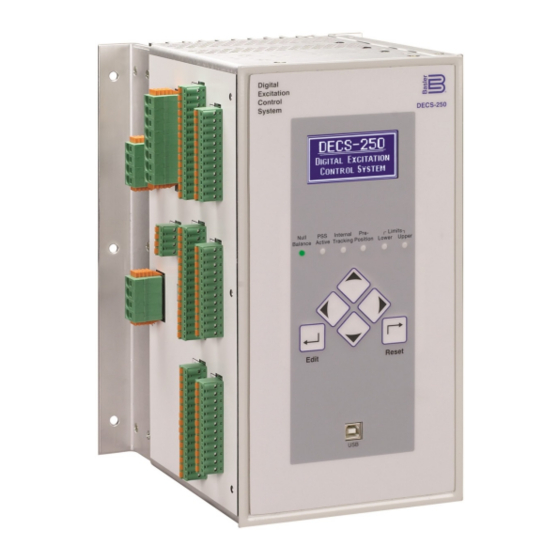
(LCD). Front Panel Illustration and Description DECS-250 controls and indicators are illustrated in Figure 2 and described in Table 1. The locators and descriptions of Table 1 correspond to the locators shown in Figure 2. Figure 2. Front Panel Controls and Indicators... -
Page 22: Menu Navigation
“bumpless” transfer when changing active modes. Menu Navigation The DECS-250 provides local access to DECS-250 settings and metering values through a menu structure displayed on the front panel LCD. An overview of the menu structure is illustrated in Figure 3. -
Page 23: Adjusting Settings
LCD backlight when no pushbutton activity is seen for the duration of the LCD Backlight Timeout setting Language Language modules are available for the DECS-250. Once a language module is implemented it can be enabled via the Language Selection setting DECS-250... -
Page 24: Screen Scrolling
Synchronization Primary, Aux Input, Tracking, Real Time Clock, Contact Inputs, Contact Outputs, or Device ID. Follow this selection by the desired parameters within each category. Enable Scroll: Enable or disable. Scroll Time Delay (s): Adjustable from 1 to 600 seconds in 1 second increments. Controls and Indicators DECS-250... -
Page 25: Power Inputs
During DECS-250 power-up, the optional ICRM prevents damage to the DECS-250 by limiting inrush current to a safe level. When operating power is applied to the DECS-250, the ICRM limits the inrush current by adding a high level of resistance between the DECS-250 and the power source. Once the inrush current subsides, the series resistance diminishes quickly to allow nominal, steady-state current flow. - Page 26 To prevent damage to the DECS-250, the use of the ICRM is recommended when using a low impedance source, such as a wall outlet. For a detailed description of the Inrush Current Reduction Module, refer to Basler publication 9387900990. ICRM connections are illustrated in the Typical Connections chapter. Power Inputs...
-
Page 27: Power Stage
9440300990 Rev J Power Stage The DECS-250 supplies regulated dc excitation power to the field of a brushless exciter. Excitation power is supplied at terminals F+ and F–. DECS-250 power stage operating power accepts single- or three-phase ac power from a transformer or PMG. - Page 28 9440300990 Rev J Power Stage DECS-250...
-
Page 29: Voltage And Current Sensing
DECS-250 terminals CTB+ and CTB–. The DECS-250 is compatible with CTs having 5 Aac or 1 Aac nominal secondary ratings. The DECS-250 uses this secondary rating, along with the CT nominal primary ratings to interpret the sensed current and calculate system parameters. -
Page 30: Cross-Current Compensation
Cross-current compensation (reactive differential) mode allows two or more paralleled generators to share a common load. As shown in Figure 7, each generator is controlled by a DECS-250 using the DECS-250 cross-current compensation input (terminals CCCT+ and CCCT–) and a dedicated, external current transformer (CT) to sense generator current. -
Page 31: Bus Voltage
These features are discussed in the Synchronizer chapter of this manual. Three-phase bus sensing voltage is applied to DECS-250 terminals B1, B2, and B3. This sensing voltage is typically applied through a user-supplied voltage transformer, but may be applied directly. - Page 32 9440300990 Rev J Voltage and Current Sensing DECS-250...
-
Page 33: Synchronizer
Two modes of generator synchronization are available: phase lock loop and anticipatory . In either mode, the DECS-250 matches the voltage, phase angle, and frequency of the generator with the bus and then connects the generator to the bus by closing the generator breaker. Anticipatory mode has the added capability of compensating for the breaker closing time. -
Page 34: Angle Compensation
DECS-250 metered slip angle reads –30°. Equation 1, below, illustrates the DECS-250 slip angle calculation. This means that the generator angle is lagging behind the bus angle by 30° due to transformer phase shift. To compensate for this phase shift, the angle compensation setting should contain a value of 330°. -
Page 35: Voltage Matching
Figure 12. Breaker Failure When a close command is issued to the breaker, the DECS-250 monitors the breaker status and annunciates a breaker failure if the breaker does not close within the time defined by the breaker close wait delay . -
Page 36: Generator And Bus Condition Detection
HMI Navigation Path: Settings, Sync/Voltage Matching, Bus Condition Detection The DECS-250 monitors the voltage and frequency of the generator and bus for determining when a breaker closure is appropriate. Generator and bus condition detection settings are illustrated in Figure 13. -
Page 37: Generator Stability
Bus Condition A dead bus is recognized by the DECS-250 when the bus voltage decreases below the dead bus threshold for the duration of the dead bus activation delay... - Page 38 Bus Stability Overvoltage Pickup and Dropout: Adjustable from 10 to 600,000 Vac in 1 Vac increments. Bus Stability Undervoltage Pickup and Dropout: Adjustable from 10 to 600,000 Vac in 1 Vac increments. Bus Stability Overfrequency Pickup and Dropout: Adjustable from 46 to 64 Hz in 0.05 Hz increments. Synchronizer DECS-250...
-
Page 39: Generator Governor Control
During synchronization, the DECS-250 adjusts the generator voltage and frequency by issuing speed correction signals to the speed governor. Correction signals are issued in the form of DECS-250 output contact closures. These correction signals may be either continuous or proportional . - Page 40 9440300990 Rev J Synchronizer DECS-250...
-
Page 41: Regulation
WECC testing requirements. FVR mode can also be used to smooth the transfer from the active DECS-250 to a secondary DECS. When operating in FVR mode, the DECS-250 regulates the level of field voltage it supplies to the field based on the FVR setpoint . -
Page 42: Var
Var mode settings are illustrated in Figure 16. Power Factor When operating in Power Factor (PF) mode, the DECS-250 controls the var output of the generator to maintain the Power Factor setpoint as the kW load on the generator varies. The setting range of the PF... -
Page 43: Pre-Position Setpoints
(kW) where the DECS-250 switches to/from Droop Compensation/Power Factor mode. If the level of power decreases below the setting, the DECS-250 switches from Power Factor mode to Droop Compensation mode. Conversely, as the level of power increases above the setting, the DECS- 250 switches from Droop Compensation mode to Power Factor mode. -
Page 44: Transient Boost
The transient excitation boosting function improves response to successive faults by providing increased excitation support. When a simultaneous line current increase and line voltage decrease occurs, the DECS-250 compensates by elevating the voltage setpoint above the nominal setpoint. When the line voltage recovers, the voltage setpoint is restored to the nominal value. -
Page 45: Reactive Droop Compensation
A Load Share ID setting identifies the DECS-250 as a load sharing unit in the network. Checking a Load Sharing Unit number box allows any DECS-250 load sharing units on the network with that Load Share ID number to share load with the currently connected DECS-250. -
Page 46: Line Drop Compensation
, line drop compensation can be used to maintain voltage at a load located at a distance from the generator. The DECS-250 achieves this by measuring the line current and calculating the voltage for a specific point on the line. Line drop compensation is applied to both the real and reactive portion of the generator line current. -
Page 47: Autotracking
BESTCOMSPlus Navigation Path: Settings Explorer, Operating Settings, Autotracking HMI Navigation Path: Settings, Operating Settings, Autotracking. Internal regulation mode setpoint tracking is a standard feature on the DECS-250. External setpoint tracking is optional (style xx2xxxx). Autotracking settings are illustrated in Figure 20. -
Page 48: External Setpoint Tracking
External Tracking Traverse Rate: Adjustable from 1 to 80 seconds in 0.1 second increments. Setpoint Configure When the Auto Save setting is enabled, the DECS-250 automatically saves the active setpoint in one- minute intervals. Otherwise, the setpoint which was last sent to the DECS-250 is retained. Figure 21 illustrates the Setpoint Configure screen. -
Page 49: Auxiliary Control
Minimum and maximum setpoint limits are observed when the With Limit box is checked. Auxiliary Control Gains When a current input type is selected, the input current is converted internally by the DECS-250 into a voltage signal in the range of –10 to +10 Vdc. The DECS-250 uses the following equation when 20.0... -
Page 50: Avr Mode
The auxiliary control signal can be configured to control the inner or outer regulation control loop. Selecting the inner loop limits auxiliary control to AVR, FCR, and FVR modes. Selecting the outer loop limits auxiliary control to PF and Var modes. Figure 22. Auxiliary Input Settings Auxiliary Control DECS-250... - Page 51 FVR (Mode) Gain: Adjustable from –99 to +99 in 0.01 increments. Var (Mode) Gain: Adjustable from –99 to +99 in 0.01 increments. PF (Mode) Gain: Adjustable from –99 to +99 in 0.01 increments. Summing Type: Select Inner Loop or Outer Loop. DECS-250 Auxiliary Control...
- Page 52 9440300990 Rev J Auxiliary Control DECS-250...
-
Page 53: Contact Inputs And Outputs
BESTCOMSPlus Navigation Path: Settings Explorer, Programmable Inputs, Contact Inputs HMI Navigation Path: Not available through HMI. Sixteen contact inputs are provided for initiating DECS-250 actions. Two of the contact inputs are fixed- function inputs: Start and Stop. The remaining 14 contact inputs are programmable. An additional 10 contact inputs are available with the optional Contact Expansion Module (CEM-2020). -
Page 54: Contact Outputs
BESTCOMSPlus Navigation Path: Settings Explorer, Programmable Outputs, Contact Outputs HMI Navigation Path: Not available through HMI. DECS-250 contact outputs consist of a dedicated watchdog output and 11 programmable outputs. An additional 18 contact outputs are available with the optional Contact Expansion Module (CEM-2020H). - Page 55 Label Text: Enter a string of up to 64 alphanumeric characters. See the Terminals and Connectors chapter for an illustration of the programmable output terminals. Contact output electrical ratings are listed in the Specifications chapter. DECS-250 Contact Inputs and Outputs...
- Page 56 9440300990 Rev J Contact Inputs and Outputs DECS-250...
-
Page 57: Protection
Several volts per hertz settings enable the DECS-250 to provide flexible generator and generator step-up transformer overexcitation protection. An inverse square timing characteristic is provided through the... - Page 58 9440300990 Rev J Figure 25. V/Hz Characteristic – Time Shown on Vertical Axis Figure 26. V/Hz Characteristic – Time Shown on Horizontal Axis Protection DECS-250...
-
Page 59: Generator Undervoltage
Figure 28. Generator Undervoltage Protection Settings Generator Undervoltage Pickup (V): Adjustable from 0 to 600,000 Vac in 1 Vac increments. Generator Undervoltage Time Delay (s): Adjustable from 0.1 to 60 seconds in 0.1 second increments. Generator Undervoltage Enable/Disable: Select Enabled or Disabled. DECS-250 Protection... -
Page 60: Generator Overvoltage
The generator voltage is monitored for a loss of sensing (LOS) condition. LOS protection settings are illustrated in Figure 30. In the DECS-250, a loss of sensing event is calculated using sequence components. A loss of sensing event occurs when the positive sequence voltage drops below the balanced... -
Page 61: Frequency Protection
Figure 31. Overfrequency Protection Settings Overfrequency (81O) Pickup (Hz): Adjustable from 30 to 70 hertz in 0.01 hertz increments. Overfrequency (81O) Time Delay (s): Adjustable from 0.1 to 300 seconds in 0.1 second increments. Overfrequency (81O) Mode: Select Disabled or Over. DECS-250 Protection... -
Page 62: Underfrequency
Reverse power pickup and trip elements in BESTlogicPlus can be used in a logic scheme to initiate corrective action in response to the condition. BESTCOMSPlus reverse power protection settings are illustrated in Figure 33. Protection DECS-250... -
Page 63: Loss Of Excitation
See Figure 34 for details. Motor Protection The DECS-250 compares the real power (kW) flowing into the motor with the reactive power (kvar) being supplied. Operation of synchronous motors drawing reactive power from the system can result in overheating in parts of the rotor that do not normally carry current. -
Page 64: Field Protection
Pickup (% of rated vars): Adjustable from 0 to 150% in 1% increments. Time Delay: Adjustable from 0 to 300 seconds in 0.1 second increments. Mode: Select Disabled or Enabled. Field Protection BESTCOMSPlus Navigation Path: Settings Explorer, Protection, Field HMI Navigation Path: Settings, Protection, Field Protection DECS-250... -
Page 65: Field Overvoltage
9440300990 Rev J Field protection provided by the DECS-250 includes field overvoltage, field overcurrent, an exciter diode monitor, and power input failure. Field Overvoltage A field overvoltage condition occurs when the field voltage exceeds the field overvoltage threshold for the duration of the field overvoltage time delay . -
Page 66: Exciter Diode Monitor
1.5 or higher and the level of field current should be no less than 1.5 Adc. A pole ratio calculator, available in BESTCOMSPlus, can be used to calculate the pole ratio from the number of exciter armature and generator rotor poles. Protection DECS-250... - Page 67 However, reducing the multiplier could result in nuisance shorted diode indications. The DECS-250 has fixed EDM inhibit levels to prevent nuisance failed-diode indications while the generator frequency is less than 40 hertz or greater than 70 hertz. EDM operation is also inhibited when the level of field current is below the disable level setting.
-
Page 68: Power Input Failure
Setting the Pickup Level—Number of Generator Poles Unknown The DECS-250 can detect shorted diode conditions when the number of generator poles is not known. To provide this protection, disable open diode protection, set the pole ratio at zero, and enable shorted diode protection. -
Page 69: Sync-Check Protection
25 status virtual output asserts. This virtual output can be configured (in BESTlogicPlus) to assert a DECS-250 contact output. This contact output can, in turn, enable the closure of a breaker tying the generator to the bus. -
Page 70: Generator Frequency Less Than 10 Hertz
BESTCOMSPlus Navigation Path: Settings Explorer, Protection, Configurable Protection HMI Navigation Path: Settings, Protection, Configurable Protection The DECS-250 has eight configurable protection elements which can be used to supplement the standard DECS-250 protection. BESTCOMSPlus configurable protection settings are illustrated in Figure 41. To... - Page 71 RTD Input 1, 2, 3, 4, 5, 6, 7, or 8 • Thermocouple 1 or 2 Protection can be always enabled or enabled only when the DECS-250 is enabled and supplying excitation . When protection is enabled only in Start mode, an arming time delay can be used to delay protection following the start of excitation.
- Page 72 Hysteresis: Adjustable from 0 to 100% of the threshold setting in 0.1% increments. Mode: Select Over, Under, or Disabled. Threshold: Adjustable from –999,999 to +999,999 in 0.01 increments. Activation Delay (s): Adjustable from 0 to 300 seconds in 1 second increments. Protection DECS-250...
-
Page 73: Limiters
When the excitation level exceeds the high level setting, the DECS-250 acts to limit the excitation to the value of the high-level setting. If this level of excitation persists for the duration of the high time setting, the DECS-250 acts to limit the excitation to the value of the low-level setting. - Page 74 DECS-250. The generator is permitted to operate indefinitely with this level of excitation. When the excitation level exceeds the low-level setting for the duration of the medium time setting, the DECS-250 acts to limit the excitation to the value of the low-level setting.
-
Page 75: Takeover Oel
Summing Point OEL Online Medium Level: Adjustable from 0 to 20 Adc in increments of 0.01 Adc. Summing Point OEL Online Medium Time: Adjustable from 0 to 120 s in 1 s increments. Summing Point OEL Online High Level: Adjustable from 0 to 30 Adc for the DECS-250. The setting increment is 0.01 Adc. - Page 76 , a plot of the takeover OEL setting curves is displayed. Settings enable selection of the displayed curves. The plot can display the primary or secondary setting curves, the offline or online settings curves, and the pick up or reset settings curves. Limiters DECS-250...
-
Page 77: Underexcitation Limiter
. The internally-generated curve is based on the desired reactive power limit at zero real power with respect to the generator voltage and current rating. The absorbed reactive power axis of the curve on the UEL Custom Curve screen can be tailored for your application. DECS-250 Limiters... - Page 78 Figure 49. UEL Custom Curve Screen UEL Configuration Enable: Check box to enable underexcitation limiter. Curve Selection: Select Internal or Customized. Internal Curve: Enter number to adjust range of y axis. Custom Curve: Insert, enter, and delete curve data points as needed. Limiters DECS-250...
-
Page 79: Stator Current Limiter
, the DECS-250 annunciates the elevated level. If this condition persists for the duration of the High SCL Time setting, the DECS-250 acts to limit the current to the low-level SCL Setting. The generator is permitted to operate indefinitely at or below the low- level threshold. -
Page 80: Var Limiter
VA rating for the machine. A delay setting establishes a time delay between when the var threshold is exceeded and the DECS-250 acts to limit the var flow. Var limiter settings are illustrated in Figure 52. -
Page 81: Underfrequency Limiter
9440300990 Rev J Automatic adjustment (scaling) of the overexcitation limiter and stator current limiter is possible through the DECS-250 auxiliary control input. Limiter scaling settings are illustrated in Figure 53. OEL and SCL scaling may be independently enabled and disabled . -
Page 82: Volts Per Hertz
The high limiter setting establishes the maximum threshold for volts per hertz limiting, the low limiter setting establishes the minimum threshold for volts per hertz limiting, and the time limiter setting establishes the time delay for limiting. Limiters DECS-250... - Page 83 Underfrequency Limiter Slope: Adjustable from 0 to 3 in increments of 0.01. V/Hz High Limiter: Adjustable from 0 to 3 in increments of 0.01. V/Hz Low Limiter: Adjustable from 0 to 3 in increments of 0.01. V/Hz Time Limiter: Adjustable from 0 to 10 s in 0.2 s increments. DECS-250 Limiters...
- Page 84 9440300990 Rev J Limiters DECS-250...
-
Page 85: Metering
The DECS-250 provides comprehensive metering of internal and system conditions. These capabilities include extensive parameter metering, status indication, reporting, and real-time metering analysis. Metering Explorer DECS-250 metering is accessed through the metering explorer menu on the front panel HMI or the ® BESTCOMSPlus metering explorer. -
Page 86: Metered Parameters
Dragging the blue square anywhere other than one of the arrow/tab boxes places the selected metering screen as a floating window. Metered Parameters DECS-250 metering categories include generator, power, bus, field, power system stabilizer (PSS), and generator synchronization parameters. Generator... -
Page 87: Bus
Figure 60. Energy When operating in motor mode, values for var and power factor will be opposite in BESTCOMSPlus and on the front-panel HMI. See Table 3. Table 3. Operating Mode DECS-250 Operating Mode Sign of Vars Generator Motor Positive (+) -
Page 88: Field
PSS output level. The PSS function on/off status is also reported. Primary- and per-unit values are available. Figure 63 illustrates the PSS primary-values metering screen. Metering DECS-250... -
Page 89: Synchronization
HMI Navigation Path: Metering Explorer, Aux Input The control signal applied at the DECS-250 auxiliary control input is indicated on the Aux Input metering screen (Figure 65). As configured in BESTCOMSPlus, a dc voltage or dc current signal may be applied. -
Page 90: Control Panel
PF are displayed, as well as Alarm status, PSS status, and Null Balance status. Figure 67. Control Panel Start/Stop Mode: Two indicators show the start/stop mode of the DECS-250. When a mode is active, its corresponding indicator changes from gray to green. To select the DECS-250 Start status, click the Start button. -
Page 91: Metering Summary
All of the metering values displayed on the individual, previously-described metering screens are consolidated on the metering summary screen. Primary- and per-unit values are available. Figure 68 illustrates the primary-values metering summary screen. The primary- and per-unit metering summary screens are available only in BESTCOMSPlus. DECS-250 Metering... -
Page 92: Status Indication
9440300990 Rev J Figure 68. Metering Summary Screen Status Indication Status indication is provided for DECS-250 system functions, inputs, outputs, network load share, configurable protection, alarms, and the real-time clock. System Status BESTCOMSPlus Navigation Path: Metering Explorer, Status, System Status... -
Page 93: Inputs
Annunciation is also provided for the optional Analog Expansion Module (AEM-2020) inputs. DECS-250 Contact Inputs Status indication for the DECS-250’s 16 contact sensing inputs is provided on the BESTCOMSPlus contact inputs screen illustrated in Figure 70. An indicator changes from gray to red when a closed contact is sensed at the corresponding input. -
Page 94: Outputs
Module (AEM-2020) analog outputs. DECS-250 Contact Outputs Status indication for the DECS-250’s Watchdog and 11 contact outputs is provided on the BESTCOMSPlus contact outputs screen illustrated in Figure 71. An indicator changes from gray to green when the corresponding output changes state (Watchdog output) or closes (Output 1 through 11). -
Page 95: Network Load Share
9440300990 Rev J Figure 71. DECS-250 Contact Outputs Status Indication Screen Network Load Share The screen shown in Figure 72 reports the error percent, reactive current, NLS average reactive current, and number of generators online. The status indicators change from gray to green when a status is active. -
Page 96: Alarms
Reset pushbutton. A Reset Alarms button on the Alarms screen is clicked to clear all inactive alarms in BESTCOMSPlus. The BESTCOMSPlus Alarms screen is illustrated in Figure 74. All possible DECS-250 alarms are listed below. Figure 74. DECS-250 Alarm Annunciation and Reset Screen... - Page 97 Exciter Open Diode RTD Input 6 Threshold 1 Trip Exciter Shorted Diode RTD Input 6 Threshold 2 Trip Failed to Build Up Alarm RTD Input 6 Threshold 3 Trip Field Short Circuit Status RTD Input 6 Threshold 4 Trip DECS-250 Metering...
- Page 98 Disabled, Latching, or Non-Latching. Latching alarms are stored in nonvolatile memory and are retained even when control power to the DECS-250 is lost. Active alarms are shown on the front panel LCD and in BESTCOMSPlus until they are cleared. Non-latching alarms are cleared when control power is removed.
-
Page 99: Real-Time Clock
The DECS-250 time and date is displayed and adjusted on the BESTCOMSPlus Real-Time Clock screen (Figure 77). Manual adjustment of the DECS-250 clock is made by clicking the Edit button. This displays a window where the DECS-250 time and date can be adjusted manually or according to the connected PC clock’s date and time. -
Page 100: Auto Export Metering
Found under the Tools menu, the auto export metering function is an automated method for saving multiple metering data files at specific intervals over a period of time while connected to a DECS-250. The user specifies the Number of Exports and the Interval between each export. Enter a base filename for the metering data and a folder in which to save. -
Page 101: Event Recorder
HMI Navigation Path: Metering Explorer, Reports, Sequence of Events A sequence of events recorder monitors the internal and external status of the DECS-250. Events are scanned at four millisecond intervals with 1,023 events stored per record. All changes of state that occur during each scan are time- and date-stamped. -
Page 102: Setup
Total Duration: Read-only value is the sum of the pre- and post-trigger duration values. Triggers BESTCOMSPlus Navigation Path: Settings Explorer, Report Configuration, DataLog HMI Navigation Path: Settings, Configuration Settings, Data Log Data logging may be triggered by mode triggers, logic triggers, level triggers, or manually through BESTCOMSPlus. Event Recorder DECS-250... - Page 103 9440300990 Rev J Mode Triggers Mode triggers initiate data logging as a result of an internal or external DECS-250 status change. A data log can be triggered by any of the following status changes: • Start or Stop mode selected •...
- Page 104 • • Generator current Ic PSS mechanical power LP #2 • • Generator frequency PSS mechanical power LP #3 • • Generator power factor PSS mechanical power LP #4 • • Generator reactive power PSS post-limit output Event Recorder DECS-250...
-
Page 105: Trending
Trending BESTCOMSPlus Navigation Path: Settings Explorer, Report Configuration, Trending HMI Navigation Path: Settings, Configuration Settings, Trending The trend log records the activity of DECS-250 parameters over an extended period of time. When enabled , up to six selectable parameters can be monitored over a user-defined duration ranging from one to 720 hours. - Page 106 {p.u.}, AvrOut, FcrErr, FcrState, FcrOut, FvrErr, FvrState, FvrOut, var/PfErr, var/PfState, var/PfOut, OelState, UelState, SclState, varLimState, Droop,Rcc, OelRef, UelRef, SclIRef, SclPfRef, varLimRef, ProgrammableDiagnotic1, ProgrammableDiagnotic2, ProgrammableDiagnotic3, ProgrammableDiagnotic4, ProgrammableDiagnotic5, or ProgrammableDiagnotic6. Trending Duration: Adjustable from 1 to 720 hours in 1 hour increments. Event Recorder DECS-250...
-
Page 107: Power System Stabilizer
PSS function is illustrated by the function blocks and software switches shown in Figure 85. This illustration is also available in BESTCOMSPlus by clicking the PSS Model Info button located on the Control tab. DECS-250 Power System Stabilizer... - Page 108 9440300990 Rev J Figure 85. PSS Function Blocks and Software Switches Power System Stabilizer DECS-250...
-
Page 109: Speed Signal
However, this may not be the case during low frequency transients, due to the voltage drop across the machine reactance. To compensate for this effect, the DECS-250 first calculates the terminal voltages and currents. It then adds the voltage drop across the quadrature reactance to the terminal voltages to obtain internal machine voltages. -
Page 110: Derived Mechanical Power Signal
SSW 2 setting is Frequency and the SSW 3 setting is Derived Frequency/Speed. Washed out power is selected as the stabilizing signal when the SSW 3 setting is Power. (When the SSW 3 setting is Power, the SSW 2 setting has no effect.) Power System Stabilizer DECS-250... -
Page 111: Torsional Filters
The output of the phase compensation stages is connected, through a stabilizer gain stage, to the washout filter and logic limiter. Software switch SSW 9 enables and bypasses the washout filter and logic limiter. The washout filter has two time constants: normal and limit (less than normal). DECS-250 Power System Stabilizer... -
Page 112: Output Stage
Since the PSS operates by modulating the excitation, it may counteract the voltage regulator’s attempts to maintain terminal voltage within a tolerance band. To avoid creating an overvoltage condition, the PSS has a terminal voltage limiter (shown in Figure 92) that reduces the upper output limit to zero when the Power System Stabilizer DECS-250... - Page 113 The low-pass filter is controlled by a time constant Figure 94. PSS Configuration Settings Figure 95. PSS Control Settings DECS-250 Power System Stabilizer...
- Page 114 9440300990 Rev J Figure 96. PSS Parameter Settings Power System Stabilizer DECS-250...
- Page 115 Low-Pass/Ramp Tracking Exponent Denominator: Adjustable from 1 to 5 in increments of 1. PSS Signal Software Switch SSW 2: Select Frequency or Der. Speed. PSS Signal Software Switch SSW 3: Select Power or Der. Freq/Speed. Torsional Filter 1 Software Switch SSW 4: Select Disabled or Enabled. DECS-250 Power System Stabilizer...
- Page 116 Terminal Voltage Limiter Setpoint: Adjustable from 0 to 10 in 0.001 increments. Terminal Voltage Limiter Software Switch SSW 8: Select Enabled or Disabled. Terminal Voltage Limiter Time Constant: Adjustable from 0.02 to 5 in 0.01 increments. Power System Stabilizer DECS-250...
-
Page 117: Stability Tuning
Proportional, Integral, Derivative. The word proportional indicates that the response of the DECS-250 output is proportional or relative to the amount of difference observed. Integral means that the DECS-250 output is proportional to the amount of time that a difference is observed. Integral action eliminates offset. - Page 118 Upon completion of stability tuning, undesired records can be removed from the record list. Caution Calculated or user-defined PID values are to be implemented only after their suitability for the application has been verified by the user. Incorrect PID numbers can result in poor system performance or equipment damage. Stability Tuning DECS-250...
-
Page 119: Auto Tuning
Power Input Mode . When the desired settings are selected, the Start Auto Tune button is clicked to start the process. After the process is complete, click the Save PID Gains (Primary) button to save the data. DECS-250 Stability Tuning... -
Page 120: Fcr And Fvr Modes
BESTCOMSPlus FCR stability settings and FVR stability settings are illustrated in Figure 101. FCR Mode Stability Settings The DECS-250 bases its field current output upon the following settings. The proportional gain (K is multiplied by the error between the field current setpoint and the actual field current value. -
Page 121: Fvr Mode Stability Settings
FVR Mode Stability Settings The DECS-250 bases its field voltage output upon the following settings. The proportional gain (K is multiplied by the error between the field voltage setpoint and the actual field voltage value. Decreasing K reduces overshoot in the transient response. -
Page 122: Other Modes And Functions
HMI Navigation Path: Settings, Operating Settings, Gains, Other Gains Settings for stability tuning of the Var and Power Factor modes are provided in the DECS-250 along with settings for stability tuning of limiters, the voltage matching function, and main field voltage response. - Page 123 – Integral Gain: Adjustable from 0 to 1,000 in 0.1 increments. VARL K – Loop Gain: Adjustable from 0 to 1,000 in 0.1 increments. Voltage Matching K – Integral Gain: Adjustable from 0 to 1,000 in 0.001 increments. DECS-250 Stability Tuning...
- Page 124 9440300990 Rev J Stability Tuning DECS-250...
-
Page 125: Mounting
9440300990 Rev J Mounting As delivered, the DECS-250 is configured for projection (wall) mounting. Front panel mounting is possible with an optional escutcheon kit. Kits are supplied with an escutcheon and screws for securing the escutcheon to the DECS-250. Request part number 9440311101. This kit is suitable for new installations and when replacing a DECS-200 with the DECS-250. - Page 126 9440300990 Rev J Figure 103. Overall and Projection Mounting Dimensions Mounting DECS-250...
- Page 127 9440300990 Rev J Figure 104. DECS-250 Escutcheon Plate Dimensions DECS-250 Mounting...
- Page 128 9440300990 Rev J Figure 105. Panel Cutting and Drilling Dimensions for DECS-250 Panel Mounting Mounting DECS-250...
-
Page 129: Terminals And Connectors
9440300990 Rev J Terminals and Connectors DECS-250 terminals and connectors are located on the left side panel, front panel, and right side panel. DECS-250 terminals consist of single-row, multiple-pin headers that mate with removable connectors wired by the user. DECS-250 connectors vary according to their function and the specified options. - Page 130 RLY 5 RLY 6 IN 13 RLY 6 RLY 7 IN 14 RLY 7 RLY 8 RLY 8 RLY 9 RLY 9 RLY 10 RLY 10 RLY 11 RLY 11 Figure 106. Left Side Panel Terminals Terminals and Connectors DECS-250...
- Page 131 Description These terminals accept three-phase operating power for the excitation power stage of the DECS-250. A ground for the operating power connections is provided at terminal GND. Excitation power is supplied to the field through the terminals labeled F+ and F–.
- Page 132 9440300990 Rev J IRIG -- - IRIG Figure 107. Right Side Connectors and Terminals Terminals and Connectors DECS-250...
-
Page 133: Terminal Types
(not shown). Terminal Types Spring terminals are supplied on DECS-250 controllers with a style number of xxxSxxx. These removable connectors secure each wire with a spring-loaded contact. Compression terminals are supplied for the operating power terminals (locator A), field power output terminals (locator B), and current sensing terminals (locator C) when a style number of xxxCxxx is specified. - Page 134 Spring terminal connector blocks identified by locators A through J and M are held in place by retaining clips. Connectors identified by locators A, B, E, F, G, H, I, and J are keyed to avoid misconnections. Terminals and Connectors DECS-250...
-
Page 135: Typical Connections
9440300990 Rev J Typical Connections Typical connection diagrams are provided in this chapter as a guide when wiring the DECS-250 for communication, contact inputs, contact outputs, sensing, and operating power. Typical connections for shunt powered applications are shown in Figure 108. Typical connections for PMG powered applications are shown in Figure 109. - Page 136 9440300990 Rev J Locator Description This input/output is unassigned by default if the DECS-250 is not equipped with the optional PSS (style number xPxxxxx). RS-485 port uses the Modbus RTU protocol for communication with other networked devices. Figure 108. Typical DECS-250 Connections for Shunt Powered Applications...
- Page 137 9440300990 Rev J Figure 109. Typical DECS-250 PMG Connections for PMG Powered Applications DECS-250 Typical Connections...
- Page 138 9440300990 Rev J Figure 110. Typical DECS-250 PMG Connections for Station Powered Applications Typical Connections DECS-250...
-
Page 139: Bestcomsplus Software
DECS-250 is brought into BESTCOMSPlus by downloading settings and logic from the DECS-250. This gives the user the option of developing a custom setting file by modifying the default logic scheme or by building a unique scheme from scratch. -
Page 140: Installation
BESTCOMSPlus. Manual activation is useful if you want to create a settings file prior to receiving your digital excitation system. Note that if a DECS-250 is not connected, you will not be able to configure certain Ethernet settings. Ethernet settings can be changed only when an active USB or Ethernet connection is present. -
Page 141: Connect A Usb Cable
Windows will notify you when installation is complete. Connect a USB cable between the PC and your DECS-250. Apply operating power (per style chart in the Introduction chapter) to the DECS-250 at rear terminals A, B, and C. Wait until the boot sequence is complete. - Page 142 ® The BESTCOMSPlus platform window opens. Select New Connection from the Communication pull- down menu and select DECS-250. See Figure 114. The DECS-250 plugin is activated automatically after connecting to a DECS-250. Figure 114. Communication Pull-Down Menu The DECS-250 Connection screen shown in Figure 115 appears. Select USB Connection and click Connect.
-
Page 143: Manual Activation Of The Decs-250 Plugin
Manual activation of the DECS-250 plugin is required only if your initial use of BESTCOMSPlus will be on a PC that is not connected to a DECS-250. Manual activation is described in the following paragraphs. Requesting an Activation Key When initially running the DECS-250 plugin, the Activate Device Plugin pop-up appears. You must contact Basler Electric for an activation key before you can activate the DECS-250 plugin. -
Page 144: Establishing Communication
Select DECS-250 from the Device pull-down menu. Enter your Email Address and Activation Key provided by Basler Electric. If you received an email containing the Activation Key, you can select all of the text in the email and copy it to the Windows clipboard using normal Windows techniques. The Get Data button extracts the Device, Email Address, and Activation Key from the Windows clipboard and pastes it into the appropriate fields. - Page 145 Recent Files Open a previously opened file Exit Close BESTCOMSPlus program Communication New Connection Choose new device or DECS-250 Close Connection Close communication between BESTCOMSPlus and DECS-250 Download Settings and Logic from Download operational and logic settings from the device...
-
Page 146: Lower Menu Bar (Decs-250 Plugin)
DECS-250. Settings Explorer ® The Settings Explorer is a convenient tool within BESTCOMSPlus used to navigate through the various settings screens of the DECS-250 plugin. Descriptions of these configuration settings are organized as follows: • General Settings •... -
Page 147: Settings File Management
Upload Settings and/or Logic to Device To upload a settings file to the DECS-250, open the file or create a new file through BESTCOMSPlus. Then pull down the Communication menu and select Upload Settings and Logic to Device. If you want to upload operational settings without logic, select Upload Settings to Device. - Page 148 Compare dialog box (Figure 120) is displayed where you can view all settings (Show All Settings), view only the differences (Show Settings Differences), view all logic (Show All Logic Paths), or view only logic differences (Show Logic Path Differences). Select Close when finished. ® Figure 120. BESTCOMSPlus Settings Compare ® BESTCOMSPlus Software DECS-250...
-
Page 149: Automatic Metering Export
Figure 121. Auto Export Metering Screen Firmware Updates Future enhancements to the DECS-250 functionality may require a firmware update. Because default settings are loaded when DECS-250 firmware is updated, your settings should be saved in a file prior to upgrading firmware. Warning! Before performing any maintenance procedures, remove the DECS- 250 from service. -
Page 150: Upgrading Firmware In Expansion Modules
2020), and the optional Analog Expansion Module (AEM-2020). Embedded firmware is the operating program that controls the actions of the DECS-250. The DECS-250 stores firmware in nonvolatile flash memory that can be reprogrammed through the communication ports. It is not necessary to replace EPROM chips when updating the firmware with a newer version. -
Page 151: Upgrading Firmware In The Decs-250
Uploader screen and disconnect communication to the DECS-250. Upgrading Firmware in the DECS-250 The following procedure is used to upgrade firmware in the DECS-250. This must be completed after upgrading firmware in any expansion modules. Remove the DECS-250 from service. Refer to the appropriate site schematics to ensure that all steps have been taken to properly and completely de-energize the DECS-250. -
Page 152: Bestcomsplus Updates
General Settings > Style Number in BESTCOMSPlus. If the style number of the settings file does not match that of the DECS-250 into which it is to be loaded, disconnect from the DECS-250, then modify the style number in the settings file. -
Page 153: Bestlogic™Plus
DECS-250. The default logic schemes can also be customized to suit your application. Detailed information about logic schemes is provided later in this chapter. -
Page 154: Bestlogic™Plus Composition
Always false (Low). Logic 1 Always true (High). Physical Inputs Start Input True when the physical Start input is active. Stop Input True when the physical Stop input is active. IN1 - IN14 True when Physical Input x is active. BESTlogic™Plus DECS-250... - Page 155 True when the unit is in FCR mode. Field Flash Active True when field flash is active. Field Short True when a field short circuit condition is detected. Circuit Status FVR Active True when the unit is in FVR mode. DECS-250 BESTlogic™Plus...
- Page 156 This element functions in conjunction with the Share Status 1-4 Network Load Share Broadcast elements on all units on the network. True when the corresponding Network Load Share Broadcast element input is true on another unit on the network. BESTlogic™Plus DECS-250...
- Page 157 PSS Voltage True when the phase voltage is unbalanced and Unbalanced the PSS is active. (Optional) True when the Stator Current Limiter is active. Setpoint at Lower True when the active modes setpoint is at the lower Limit limit. DECS-250 BESTlogic™Plus...
- Page 158 The trip block is true when the corresponding pickup block threshold is exceeded for the duration of the time delay. Contact Contact Expansion Module Connected. True when Expansion an optional CEM-2020 is connected to the DECS- Module, CEM 250. Connected BESTlogic™Plus DECS-250...
- Page 159 Expansion threshold. This function alerts the user of an open Module or damaged analog input wire. Remote Analog Inputs, Out of Range 1-8 Analog True when the analog output connection is open. Expansion Module Remote Analog Outputs 1-4 DECS-250 BESTlogic™Plus...
- Page 160 Outputs can be renamed by Off-Page Output right-clicking and selecting Rename Output. Right- clicking will also show pages that the corresponding inputs can be found on. Selecting the page will take you to that page. BESTlogic™Plus DECS-250...
- Page 161 This group contains Logic Gates, Pickup and Dropout Timers, Latches, and Comment Blocks. Table 12 lists the names and descriptions of the objects in the Components group. Table 12. Components Group, Names and Descriptions Name Description Symbol Logic Gates Input Output NAND Input Output Input Output Input Output Input Output DECS-250 BESTlogic™Plus...
- Page 162 RESET (OFF) state. If both the Set and Reset inputs are on at the same time, a set priority latch will go to the SET (ON) state. Other Comment Enter user comments. Block BESTlogic™Plus DECS-250...
- Page 163 When true, this element triggers the datalog to TRIGGER begin recording data. DROOP DISABLE When true, this element disables droop when the unit is operating in AVR mode. EXTERNAL When true, this element disables external TRACKING tracking. DISABLE DECS-250 BESTlogic™Plus...
- Page 164 Open: This output is pulsed TRUE (closes the output contact it is contact input is closed, the breaker is mapped to) when the DECS-250 is providing a signal to the indicated to be closed. When the contact breaker to open. It will be a pulse if the Breaker Output Contact...
- Page 165 DISABLE units on the network to be disabled. When an input to this block is true, load share data received from that unit is ignored by the DECS-250. LOSS OF SENSING When true, this element disables the Loss of DISABLE Sensing function.
- Page 166 PSS OUTPUT When true, this element disables the output of DISABLE the PSS. The PSS continues to run, but the output is not used. (Available when the controller is equipped with the optional Power System Stabilizer, style number xPxxxxx) BESTlogic™Plus DECS-250...
- Page 167 When true, this element disables UEL when MANUAL MODE the unit is operating in Manual mode. UEL SELECT When true, this element selects secondary SECONDARY settings for UEL. SETTINGS USER When true, this element triggers a PROGRAMMABLE programmable alarm. ALARM 1 - 16 DECS-250 BESTlogic™Plus...
-
Page 168: Logic Schemes
The Active Logic Scheme The DECS-250 must have an active logic scheme in order to function. All DECS-250 controllers are delivered with a default, active logic scheme preloaded in memory. The functionality of this logic scheme is similar to the scheme provided with the DECS-200. If the function block configuration and output logic of the default logic scheme meet the requirements of your application, then only the operating settings (system parameters and threshold settings) need to be adjusted before placing the DECS-250 in service. -
Page 169: Default Logic Schemes
Modifying a logic scheme in BESTCOMSPlus does not automatically make that scheme active in the DECS-250. The modified scheme must be uploaded into the DECS-250. See the paragraphs on Sending and Retrieving Logic Schemes above. Default Logic Schemes The default logic scheme for PSS-disabled systems is shown in Figure 124 through Figure 126 and the default logic scheme for PSS-enabled systems is shown in Figure 127 through Figure 130. - Page 170 9440300990 Rev J Figure 125. PSS-Disabled Default Logic - Logic Page 2 Tab Figure 126. PSS-Disabled Default Logic - Physical Outputs Tab BESTlogic™Plus DECS-250...
- Page 171 9440300990 Rev J Figure 127. PSS-Enabled Default Logic - Logic Page 1 Tab Figure 128. PSS-Enabled Default Logic - Logic Page 2 Tab DECS-250 BESTlogic™Plus...
-
Page 172: Programming Bestlogic™Plus
® Use BESTCOMSPlus to program BESTlogicPlus. Using BESTlogicPlus is analogous to physically attaching wire between discrete DECS-250 terminals. To program BESTlogicPlus, use the Settings Explorer within BESTCOMSPlus to open the BESTlogicPlus Programmable Logic tree branch as shown in Figure 123. -
Page 173: Pickup And Dropout Timers
A red X indicates that an object or element is not available per the style number of the DECS-250. The view of the Main Logic and Physical Outputs can be automatically arranged by clicking the right mouse button on the window and selecting Auto-Layout. -
Page 174: Offline Logic Simulator
To manage BESTlogicPlus files, use the Settings Explorer to open the BESTlogicPlus Programmable Logic tree branch. Use the BESTlogicPlus Programmable Logic toolbar to manage BESTlogicPlus files. Refer to Figure 133. For information on Settings Files management, refer to the BESTCOMSPlus Software chapter. BESTlogic™Plus DECS-250... -
Page 175: Saving A Bestlogicplus File
Logic Document from the Protection drop-down button. Establishing a password is optional. Uploading a BESTlogicPlus File To upload a BESTlogicPlus file to the DECS-250, you must first open the file through BESTCOMSPlus or create the file using BESTCOMSPlus. Then pull down the Communication menu and select Upload Logic. -
Page 176: Clearing The On-Screen Logic Diagram
Example 2 - AND Gate Connections Figure 135 illustrates a typical AND gate connection. In this example, Output 11 will become active when the bus and the generator are dead. Figure 135. Example 2 - AND Gate Connections BESTlogic™Plus DECS-250... -
Page 177: Communication
All DECS controllers mentioned here use a female DB-9 (RS-232) connector for communication with a second DECS. On the DECS-250, this connector is located on the right side panel and is illustrated in the Terminals and Connectors chapter of this manual. A five-foot (1.5 meter) cable, part number 9310300032, is available for interconnecting two DECS controllers. -
Page 178: Modbus™ Communication
BESTCOMSPlus Navigation Path: Settings Explorer, Communications, Modbus Setup HMI Navigation Path: Not available through HMI. DECS-250 systems support the RS-485 mode and Modbus/TCP (Ethernet) mode at the same time. DECS-250 Modbus communication registers are listed and defined in the Modbus Communication chapter of this manual. -
Page 179: Ethernet Port
9440300990 Rev J TO RS-422/RS-485 TO DECS-250 DB-37 FEMALE DECS-250 RS485 DECS-250 RS485 4000 ft 1219.2 m maximum DECS-250 RS485 R = Optional terminating resistor 120 ohms, typical Figure 138. Typical RS-485 Connections RS-485 port communication settings are illustrated in Figure 139 and consist of the baud rate... -
Page 180: Connections
(CEM-2020) and analog expansion module (AEM-2020). A second CAN interface (CAN 2) enables the DECS-250 to provide generator and system parameters to a generator controller such as the Basler DGC-2020. CAN 2 also permits DECS-250 setpoint and mode control from an external device connected to the CAN. -
Page 181: Ethernet Communication
The DECS-250 Connection window appears. (Figure 142) If you know the IP address of the DECS-250, click the radio button for the Ethernet Connection IP at the top of the DECS-250 Connection window, enter the address into the fields and click the Connect button. - Page 182 9440300990 Rev J Figure 142. DECS-250 Connection Window Figure 143. Scanning for Connected Devices Figure 144. Device Discovery Window Communication DECS-250...
- Page 183 Device Directory. The Device Directory stores the name, model, and address of devices you have added. Click the radio button for Select Device to Connect to, select the device from the Device Directory list, and click the Connect button at the top of the DECS-250 Connection window.
-
Page 184: Profibus Communication
On units equipped with the PROFIBUS communication protocol (style xxxxxxP), the DECS-250 sends and receives PROFIBUS data through a DB-9 port located on the right side panel. DECS-250 PROFIBUS communication parameters are listed and defined in the PROFIBUS Communication chapter of this manual. -
Page 185: Configuration
9440300990 Rev J Configuration Before the DECS-250 is placed in service, it must be configured for the controlled equipment and application. Generator, Field, and Bus Ratings BESTCOMSPlus Navigation Path: Settings Explorer, System Parameters, Rated Data HMI Navigation Path: Settings, System Parameters, Rated Data Generator, field, and bus rating settings are illustrated in Figure 148. -
Page 186: Bridge
HMI Navigation Path: Settings, System Parameters, Sensing Transformers DECS-250 configuration includes entry of the primary and secondary values for the transformers that supply generator and bus sensing values to the DECS-250. These configuration settings are illustrated in Figure 150. Configuration... -
Page 187: Generator Pt
Current settings for the generator CT primary and secondary windings establish the nominal CT current values expected by the DECS-250. DECS-250 sensing current can be obtained from a single phase or all three generator phases Bus PT Voltage settings for the bus PT primary... -
Page 188: Soft Start
The field flash time defines the maximum length of time that field flashing may be applied during startup. To use the field flashing function, one of the DECS-250 programmable contact outputs must be configured as a field flashing output. Figure 151. Startup Function Settings Soft Start Level (%): Adjustable from 0 to 90% in 1% increments. -
Page 189: Firmware And Product Information
Firmware and product information can be viewed on the HMI display and Device Info tab of BESTCOMSPlus. Firmware Information Firmware information is provided for the DECS-250, optional CEM-2020, and optional AEM-2020. This information includes the application part number , version number , and build date . -
Page 190: Display Units
Display Units BESTCOMSPlus Navigation Path: General Settings, Display Units HMI Navigation Path: N/A When working with DECS-250 settings in BESTCOMSPlus, you have the option of viewing the settings in English or Metric units and as primary units or per-unit values . -
Page 191: Security
9440300990 Rev J Security DECS-250 security is provided in the form of passwords which control the type of operations allowed by a particular user. Passwords can be tailored to provide access to specific operations. Additional security is available by controlling the type of operations allowed through certain DECS-250 communication ports. -
Page 192: Port Security
An additional dimension of security is provided by the ability to restrict the control available through the DECS-250 communication ports. At any given time, only one port can be in use with read or higher access. For example, if a user gains settings access at one port, users at other ports will be able to gain no higher than read access until the user with settings access logs off. -
Page 193: Login And Access Controls
A login time window limits the length of time permitted during the login process. If login is unsuccessful, access is blocked for the duration of the login lockout time setting DECS-250 Security... - Page 194 Access Timeout: Adjustable from 10 to 3,600 s in 1 s increments. Login Attempts: Adjustable from 1 to 10 in increments of 1. Login Time Window: Adjustable from 1 to 99,999 s in 1 s increments. Login Lockout Time: Adjustable from 1 to 99,999 s in 1 s increments. Security DECS-250...
-
Page 195: Timekeeping
HMI Navigation Path: Settings, General Settings, Clock Setup Time and Date Format Clock display settings enable you to configure the time and date reported by the DECS-250 to match the conventions used in your organization/facility. The reported time can be configured for either the 12- or 24-hour format with the Time Format setting. - Page 196 DST Stop Day of Week: Select desired day of the week for DST stop. DST Stop Hour: Adjustable from hour 0 to 23 in 1 hour increments. DST Stop Minutes: Adjustable from minute 0 to 59 in 1 minute increments. Timekeeping DECS-250...
- Page 197 Minute offset is adjustable over the range of –59 to 59 minutes in 1 minute increments. Time Priority Setup: Sort available time sources using the two arrow buttons. IRIG Decoding: Select IRIG without Year or IRIG with Year. DECS-250 Timekeeping...
- Page 198 9440300990 Rev J Timekeeping DECS-250...
-
Page 199: Testing
9440300990 Rev J Testing Testing of the DECS-250’s regulation and optional power system stabilizer (style XPXXXXX) performance ® is possible through the integrated analysis tools of BESTCOMSPlus Real-Time Metering Analysis BESTCOMSPlus Navigation Path: Metering Explorer, Analysis HMI Navigation Path: Analysis functions are not available through front panel HMI. -
Page 200: Graph Parameters
Network Load Share Var/PF state • • Null Balance Level (Null Balance) Var/PF output • • Null Balance State (Null State) Washed out power (WashP) • • OEL controller output (OelOutput) Washed out speed (WashW) • OEL reference Testing DECS-250... -
Page 201: Frequency Response
A Bode plot can be printed, opened, and saved in graph (.gph) format. Transfer Function The point in the DECS-250 logic circuitry where a signal is injected for analysis of magnitude and phase responses is selectable. Signal points include PSS Comp Frequency, PSS Electric Power, AVR Summing, AVR PID Input, and Manual PID Input. -
Page 202: Frequency Response
Tests should be performed at various load levels to confirm that the input signals are calculated or measured correctly. Since the PSS function uses compensated terminal frequency in place of speed, the derived mechanical power signal should be examined carefully to ensure that it does not contain any Testing DECS-250... -
Page 203: Signal Input
Swept Sine Test Signals Swept Sine test signals employ a unique set of characteristics that include the sweep style, frequency step, and start/stop frequencies. Sweep Type A Swept Sine test signal can be configured as linear or logarithmic. DECS-250 Testing... -
Page 204: Step Response Analysis
If logging is in progress, another log cannot be triggered. Response characteristics displayed on the Step Response Analysis screen are not automatically updated when the DECS-250 operating mode is switched externally. The screen must be manually updated by exiting and then reopening the screen. -
Page 205: Var And Pf Tabs
Layout Tab Up to six data plots may be displayed in three different layouts on the RTM screen. Place a check in the Cursors Enabled box to enable cursors used for measuring between two horizontal points. See Figure 163. DECS-250 Testing... -
Page 206: Graph Display Tab
Place a check in the Sync Graph Scrolling box to sync scrolling between all graphs when any horizontal scroll bar is moved. See Figure 164. Figure 163. Analysis Options Screen, Layout Tab Figure 164. Analysis Options Screen, Graph Display Tab Testing DECS-250... -
Page 207: Can Communication
Contact Expansion Module and Analog Expansion Module for more information. CAN bus interface 2 enables the DECS-250 to provide generator and system parameters to a generator controller such as the Basler DGC-2020. CAN 2 also permits DECS-250 setpoint and mode control from an external device connected to the CAN. - Page 208 0xF015 Requested Generator Total AC Reactive Power (var Setpoint) 3383 Requested Generator Overall PF (PF Setpoint) 3384 Requested Generator Overall PF Lagging (PF Setpoint) 3385 0xF01C Requested Generator Average L-L AC RMS Voltage Volts 3386 (AVR Setpoint) CAN Communication DECS-250...
-
Page 209: Diagnostic Trouble Codes (Dtcs)
Previously active DTCs are available upon request. Active and previously active DTCs can be cleared on request. Table 17 lists the diagnostic information that the DECS-250 obtains over the CAN bus interface. DTCs are reported in coded diagnostic information that includes the Suspect Parameter Number (SPN), Failure Mode Identifier (FMI), and Occurrence Count (OC) as listed in Table 3. - Page 210 9440300990 Rev J CAN Communication DECS-250...
-
Page 211: Modbus™ Communication
Modbus communications use a master-slave technique in which only the master can initiate a transaction. This transaction is called a query. When appropriate, a slave (DECS-250) responds to the query. When a Modbus master communicates with a slave, information is provided or requested by the master. -
Page 212: Modbus Modes Of Operation
A standard Modbus network offers the remote terminal unit (RTU) transmission mode and Modbus/TCP mode for communication. DECS-250 systems support the Modbus/TCP mode and RS-485 mode at the same time. To enable editing over Modbus TCP, or RS-485, the unsecured access level for the port must be configured to the appropriate access level. -
Page 213: Modbus On Tcp/Ip
When receiving a message via the RS-485 communication port, the DECS-250 requires an inter-byte latency of 3.5 character times before considering the message complete. Once a valid query is received, the DECS-250 waits a specified amount of time before responding. This ®... -
Page 214: Error Handling And Exception Responses
DECS-250 Modbus™ via Ethernet Modbus can communicate through Ethernet if the IP address of the DECS-250 is configured as described in the Communications chapter of this manual. Modbus™ Communication... -
Page 215: Detailed Message Query And Response For Rtu Transmission Mode
9440300990 Rev J Detailed Message Query and Response for RTU Transmission Mode A detailed description of DECS-250 supported message queries and responses is provided in the following paragraphs. Read Holding Registers Query This query message requests a register or block of registers to be read. The data block contains the starting register address and the quantity of registers to be read. -
Page 216: Restart Communications Option
Data Block byte count and data. The DECS-250 will perform the write when the device address in query is a broadcast address or the same as the DECS-250 Modbus Unit ID (device address). -
Page 217: Preset Single Register
There are several instances of registers that are grouped together to collectively represent a single numerical DECS-250 data value (i.e. - floating point data, 32-bit integer data, and strings). A query to write a subset of such a register group will result in an error response with Exception Code “Illegal Data Address”. -
Page 218: Data Formats
CRC Lo error check Response The response message echoes the Query message after the register has been altered. Data Formats DECS-250 systems support the following data types: • Data types mapped to 2 registers Unsigned Integer 32 (Uint32) Floating Point (Float) Strings maximum 4 characters long (String) •... -
Page 219: Integer Data Format (Uint16) Or Bit-Mapped Variables In Uint16 Format
Example: The string “PASSWORD” represented in string format will read as follows: Holding Register Value (Hi Byte) ‘P’ (Lo Byte) ‘A’ K+1 (Hi Byte) ‘S’ K+1 (Lo Byte) ‘S’ K+2 (Hi Byte) ‘W’ K+2 (Lo Byte) ‘O’ K+3 (Hi Byte) ‘R’ K+3 (Lo Byte) ‘D’ DECS-250 Modbus™ Communication... -
Page 220: Crc Error Check
This field contains a two-byte CRC value for transmission error detection. The master first calculates the CRC and appends it to the query message. The DECS-250 system recalculates the CRC value for the received query and performs a comparison to the query CRC value to determine if a transmission error has occurred. -
Page 221: Security
Programmable Alarm 7 40901 bit 6 Uint16 True=1 False=0 Alarms Programmable Alarm 8 40901 bit 7 Uint16 True=1 False=0 Alarms Programmable Alarm 9 40901 bit 8 Uint16 True=1 False=0 Alarms Programmable Alarm 10 40901 bit 9 Uint16 True=1 False=0 DECS-250 Modbus™ Communication... - Page 222 True=1 False=0 Block 40904 bit 8 Uint16 True=1 False=0 Status 40904 bit 9 Uint16 True=1 False=0 VM1 status 40904 bit 10 Uint16 True=1 False=0 Block 40904 bit 11 Uint16 True=1 False=0 Pickup 40904 bit 12 Uint16 True=1 False=0 Modbus™ Communication DECS-250...
- Page 223 Configurable Protection Threshold 3 Trip 40907 bit 13 Uint16 True=1 False=0 Configurable Protection 4 Configurable Protection Threshold 4 Pickup 40907 bit 14 Uint16 True=1 False=0 Configurable Protection 4 Configurable Protection Threshold 4 Trip 40907 bit 15 Uint16 True=1 False=0 DECS-250 Modbus™ Communication...
- Page 224 Input 10 40910 bit 14 Uint16 True=1 False=0 Contact Inputs Input 11 40910 bit 15 Uint16 True=1 False=0 Contact Inputs Input 12 40911 bit 0 Uint16 True=1 False=0 Contact Inputs Input 13 40911 bit 1 Uint16 True=1 False=0 Modbus™ Communication DECS-250...
- Page 225 40914 bit 1 Uint16 True=1 False=0 Contact Expansion Module Input 5 40914 bit 2 Uint16 True=1 False=0 Contact Expansion Module Input 6 40914 bit 3 Uint16 True=1 False=0 Contact Expansion Module Input 7 40914 bit 4 Uint16 True=1 False=0 DECS-250 Modbus™ Communication...
- Page 226 RTD Input 5 Out of Range 40917 bit 5 Uint16 True=1 False=0 AEM Configuration RTD Input 6 Out of Range 40917 bit 6 Uint16 True=1 False=0 AEM Configuration RTD Input 7 Out of Range 40917 bit 7 Uint16 True=1 False=0 Modbus™ Communication DECS-250...
- Page 227 True=1 False=0 AEM Protection 6 Threshold 2 Trip 40920 bit 8 Uint16 True=1 False=0 AEM Protection 6 Threshold 3 Pickup 40920 bit 9 Uint16 True=1 False=0 AEM Protection 6 Threshold 3 Trip 40920 bit 10 Uint16 True=1 False=0 DECS-250 Modbus™ Communication...
- Page 228 True=1 False=0 RTD Protection 4 Threshold 4 Pickup 40923 bit 11 Uint16 True=1 False=0 RTD Protection 4 Threshold 4 Trip 40923 bit 12 Uint16 True=1 False=0 RTD Protection 5 Threshold 1 Pickup 40923 bit 13 Uint16 True=1 False=0 Modbus™ Communication DECS-250...
- Page 229 True=1 False=0 Network Load Share Receiving ID 1 40926 bit 14 Uint16 True=1 False=0 Network Load Share Receiving ID 2 40926 bit 15 Uint16 True=1 False=0 Network Load Share Receiving ID 3 40927 bit 0 Uint16 True=1 False=0 DECS-250 Modbus™ Communication...
-
Page 230: Metering
Tracking error 41010 Float Percent DECS Regulator Meter Control output PU 41012 Float -10 - 10 DECS Regulator Meter Exciter Diode Monitor Ripple 41014 Float Percent Percent DECS Regulator Meter Power Input 41016 Float Volt 0 - 2000000000 Modbus™ Communication DECS-250... - Page 231 0 - 24 Magnitude Angle 1 Bus Voltage Meter Primary 41170 String 0 - 24 Angle 1 Bus Voltage Meter Primary 41182 String 0 - 24 Angle 1 Bus Voltage Meter Primary 41194 String 0 - 24 Angle 1 DECS-250 Modbus™ Communication...
- Page 232 Varhour 0.00E+00 - 1.00E+09 Energy Meter Positive watthour total 41330 Float Watthour 0.00E+00 - 1.00E+09 Energy Meter Positive varhour total 41332 Float Varhour 0.00E+00 - 1.00E+09 Energy Meter Negative watthour total 41334 Float Watthour -1.00E+09 - 0.00E+00 Modbus™ Communication DECS-250...
- Page 233 41408 Float Percent DECS Regulator Meter Current Magnitude Pickup 41410 Float -10 - 10 DECS Regulator Meter NLS Current Magnitude Average 41412 Float -10 - 10 Pickup DECS Regulator Meter NLS Number of Generators 41414 Int32 Online DECS-250 Modbus™ Communication...
- Page 234 Float AEM Metering Analog Input 5 Scaled Value 41504 Float AEM Metering Analog Input 6 Scaled Value 41506 Float AEM Metering Analog Input 7 Scaled Value 41508 Float AEM Metering Analog Input 8 Scaled Value 41510 Float Modbus™ Communication DECS-250...
-
Page 235: Limiters
Float 0.1 – 20 OEL Secondary Takeover Current Max On 41754 Float 0 – 30 OEL Secondary Takeover Current Min On 41756 Float 0 – 15 OEL Secondary Takeover Time Dial On 41758 Float 0.1 – 20 DECS-250 Modbus™ Communication... - Page 236 UEL Secondary Curve Y2 41822 Float kilovar 0 – 1.5 • Rated kVA UEL Secondary Curve Y3 41824 Float kilovar 0 – 1.5 • Rated kVA UEL Secondary Curve Y4 41826 Float kilovar 0 – 1.5 • Rated kVA Modbus™ Communication DECS-250...
- Page 237 Uint32 Inverse=0 Integrating=1 Instantaneous=2 OEL Primary Takeover Reset Type On 41882 Uint32 Inverse=0 Integrating=1 Instantaneous=2 OEL Secondary Takeover Reset Type Off 41884 Uint32 Inverse=0 Integrating=1 Instantaneous=2 OEL Secondary Takeover Reset Type On 41886 Uint32 Inverse=0 Integrating=1 Instantaneous=2 DECS-250 Modbus™ Communication...
-
Page 238: Setpoints
42276 and 42278. FVR Traverse Rate 42266 Float Second 10 – 200 FVR Pre-position Mode 1 42268 Uint32 Maintain=0 Release=1 FVR Pre-position 1 42270 Float Volt Setpoint adjustment range determined by registers 42276 and 42278. Modbus™ Communication DECS-250... -
Page 239: Global Settings
Table 29. Global Settings Group Parameters Group Name Register Type Bytes Unit Range PLC Timed Element Settings Logic Timer 1 Output Timeout 42400 Float 0 - 1800 PLC Timed Element Settings Logic Timer 2 Output Timeout 42402 Float 0 - 1800 DECS-250 Modbus™ Communication... - Page 240 Network Load Share Load Share Gain 42482 Float 0 - 1000 Reserved 42484-87 Generator Current Configuration Rotation 42488 Uint32 Forward=0 Reverse=1 Synchronizer Angle Compensation 42490 Float Degree 0 – 359.9 System Configuration Operating Mode 42492 Int32 Generator=0 Motor=1 Modbus™ Communication DECS-250...
-
Page 241: Relay Settings
DECS Control System Option Underfrequency Mode 42658 Uint32 UF Limiter=0 V/Hz Limiter=1 DECS Control System Option Limiter Mode 42660 Uint32 Off=0 UEL=1 OEL=2 UEL & OEL=3 SCL=4 UEL & SCL=5 OEL & SCL=6 UEL & OEL & SCL=7 DECS-250 Modbus™ Communication... -
Page 242: Protection Settings
Float 0.01 - 0.5 Voltage Difference 43160 Float 0.1 - 50 Generator Frequency Greater Than 43162 Uint32 Disabled=0 Enabled=1 Bus Frequency Dead Voltage 43164 Float Disabled=0, 10 – 90 Live Voltage 43166 Float Disabled=0, 10 – 90 Modbus™ Communication DECS-250... - Page 243 Inverse Timing=1 Field Overcurrent Time Dial, Protection Secondary 43260 Float 0.1 – 20 Primary Mode 43262 Uint32 Disabled=0,Enabled=1 Primary Definite Time Pickup 1 43264 Float 0.5 – 6 Primary Definite Time Pickup 2 43266 Float 0.5 – 6 DECS-250 Modbus™ Communication...
-
Page 244: Gains Settings
0 - 1000 Var Ki 43832 Float 0 - 1000 Var Kg 43834 Float 0 - 1000 OEL Ki 43836 Float 0 - 1000 OEL Kg 43838 Float 0 - 1000 UEL Ki 43840 Float 0 - 1000 Modbus™ Communication DECS-250... -
Page 245: Legacy Modbus
Application Version Date Character 8 47025 Uint8 Application Version Date Character 9 47026 Uint8 Reserved 47027- Uint8 0 - 255 Boot Program Version Character 1 47044 Uint8 Boot Program Version Character 2 47045 Uint8 Boot Program Version Character 3 47046 Uint8 DECS-250 Modbus™ Communication... - Page 246 = gen. failed to build up, b12 = gen. below 10Hz, b13 = unassigned, b14 = exciter diode open, b15 = exciter diode shorted. Reserved 47298 Float Active Operating Setpoint in Percent 47300 Float Contact Input States 47302 Uint16 Modbus™ Communication DECS-250...
- Page 247 1 - 600 Generator CT Primary Current Rating 47507 Float 1 - 99999 Generator CT Secondary Current Rating 47509 Int32 1=1 5=5 Not used in DECS-250 47511 Float Reserved Float 1 47513 Float 0 - 10000 Bus Sensing PT Primary Rating 47515...
- Page 248 Var Mode Setpoint Pre-Position in kvar 47643 Float kilovar Setpoint adjustment range determined by registers 47659 and 47667. PF Mode Setpoint Pre-Position 47645 Float Power Setpoint adjustment range determined Factor by registers 47661 and 47669. FCR Mode Setpoint Step Size 47647 Float Modbus™ Communication DECS-250...
- Page 249 Underfrequency Corner Frequency 47745 Float Hertz 40 - 75 Slope of Underfrequency Curve 47747 Float 0 - 3 Width of Voltage Matching Window 47749 Float Percent 0 - 20 Voltage Matching Reference 47751 Float Percent 0 - 700 DECS-250 Modbus™ Communication...
- Page 250 PF Mode Loop Gain: Kg 47881 Float 0 - 1000 OEL Loop Gain: Kg 47883 Float 0 - 1000 UEL Loop Gain: Kg 47885 Float 0 - 1000 UEL Integral Gain: Ki 47887 Float 0 - 1000 Modbus™ Communication DECS-250...
- Page 251 Loss of Field Alarm Enable 47958 Uint16 Disabled=0 Enabled=1 Loss of Field Pickup Level 47959 Float Percent Disabled=0, 0 - 150 Loss of Field Time Delay 47961 Float Millisecond Instantaneous=0, 0 - 300000 Reserved 18 47963- Filler DECS-250 Modbus™ Communication...
- Page 252 48165 Uint16 Even Parity=0 Odd Parity=1 No Parity=2 RS485 Stop Bits 48166 Uint16 1 Stop Bit=1 2 Stop Bits=2 DECS-250 Polling Address 48167 Uint16 1 - 247 Modbus Response Time Delay 48168 Uint16 Millisecond 10 - 10000 Reserved 26 48169-...
-
Page 253: Profibus Communication
If there are unused bits, they are filled with a value of zero. Parameters of UINT8 type are not affected by the DECS-250 Network Byte Order setting. The examples, below, show the bit packing order for instances 8 (Controller Status Cyclic) and 11 (Local Contact Outputs Cyclic). - Page 254 Not in var mode=0, In var mode=1 Table 36 shows the bit number of each parameter in instance 8 and an example packet returned from a DECS-250. Reading a value of 0x02 (0000 0010) for instance 8 indicates that the device is operating in FCR mode.
-
Page 255: Setup
0 (unused) 0 (unused) Setup The following steps are provided to assist in setting up the DECS-250 as a slave on a PROFIBUS network. Please refer to the documentation included with your PLC configuration software for installation and operation instructions. -
Page 256: Profibus Parameters
HMI Indicators Cyclic UINT8 DECSREGULATORMETER No Unit Not Active=0, Active=1 DECS INTERNAL TRACKING ACTIVE HMI Indicators Cyclic UINT8 DECSCONTROL DECS No Unit Active setpoint is not at a pre- PREPOSITION position value=0, Active setpoint is at a pre-position value=1 PROFIBUS Communication DECS-250... - Page 257 Local Contact Outputs UINT8 Contact Outputs Output 2 No Unit Open=0, Closed=1 Cyclic Local Contact Outputs UINT8 Contact Outputs Output 3 No Unit Open=0, Closed=1 Cyclic Local Contact Outputs UINT8 Contact Outputs Output 4 No Unit Open=0, Closed=1 Cyclic DECS-250 PROFIBUS Communication...
- Page 258 IA GG (Gen Current Angle) 0 - 360 Gen Metering Float IB GG (Gen Current Angle) 0 - 360 Gen Metering Float IC GG (Gen Current Angle) 0 - 360 Gen Metering Float IAVG GG 0 - 2000000000 PROFIBUS Communication DECS-250...
- Page 259 PSS Metering Per Unit Float Pos Seq I pu GG No Unit -10 - 10 PSS Metering Per Unit Float Neq Seq I pu GG No Unit -10 - 10 Synchronization Float Slip Angle GG -359.9 - 359.9 DECS-250 PROFIBUS Communication...
- Page 260 DECS PSS Meter DECS No Unit PSS not active=0, PSS active=1 PSS Active Control Panel Status UINT8 DECS Control DECS No Unit Not active=0, Active=1 Null Balance System Status UINT8 Alarms OEL ALM No Unit Not active=0, Active=1 PROFIBUS Communication DECS-250...
- Page 261 Open=0, Closed=1 Contact Input Status UINT8 Contact Inputs Input 6 No Unit Open=0, Closed=1 Contact Input Status UINT8 Contact Inputs Input 7 No Unit Open=0, Closed=1 Contact Input Status UINT8 Contact Inputs Input 8 No Unit Open=0, Closed=1 DECS-250 PROFIBUS Communication...
- Page 262 AEM Config AEM Input 4 No Unit Value in range=0, Value out of Out of Range range=1 AEM Analog Input Status UINT8 AEM Config AEM Input 5 No Unit Value in range=0, Value out of Out of Range range=1 PROFIBUS Communication DECS-250...
- Page 263 No Unit Not tripped-0, Tripped=1 Trip AEM Analog Input Status UINT8 AEM Protection 7 Thresh 3 No Unit Not tripped-0, Tripped=1 Trip AEM Analog Input Status UINT8 AEM Protection 7 Thresh 4 No Unit Not tripped-0, Tripped=1 Trip DECS-250 PROFIBUS Communication...
- Page 264 No Unit Not tripped=0, Tripped=1 Trip AEM RTD Input Status UINT8 RTD Protection 1 Thresh 2 No Unit Not tripped=0, Tripped=1 Trip AEM RTD Input Status UINT8 RTD Protection 1 Thresh 3 No Unit Not tripped=0, Tripped=1 Trip PROFIBUS Communication DECS-250...
- Page 265 AEM RTD Input Status UINT8 RTD Protection 8 Thresh 4 No Unit Not tripped=0, Tripped=1 Trip AEM TC Input Meter Float Thermocouple Input 1 Raw Value GG AEM TC Input Meter Float Thermocouple Input 2 Raw Value GG DECS-250 PROFIBUS Communication...
- Page 266 No Unit Open=0, Closed=1 CEM Output Status UINT8 CEM Output 15 No Unit Open=0, Closed=1 CEM Output Status UINT8 CEM Output 16 No Unit Open=0, Closed=1 CEM Output Status UINT8 CEM Output 17 No Unit Open=0, Closed=1 PROFIBUS Communication DECS-250...
- Page 267 Threshold 4 Trip Config. Prot. Status UINT8 Configurable Protection 3 No Unit Not tripped=0, Tripped=1 Configurable Protection Threshold 1 Trip Config. Prot. Status UINT8 Configurable Protection 3 No Unit Not tripped=0, Tripped=1 Configurable Protection Threshold 2 Trip DECS-250 PROFIBUS Communication...
- Page 268 Not tripped=0, Tripped=1 Configurable Protection Threshold 3 Trip Config. Prot. Status UINT8 Configurable Protection 8 No Unit Not tripped=0, Tripped=1 Configurable Protection Threshold 4 Trip Real Time Clock String Date GG No Unit 0 – 25 characters PROFIBUS Communication DECS-250...
- Page 269 System Param Float Exciter Pole Ratio GG No Unit 1 - 10 AVR Setpoints UINT32 Gen Voltage Preposition No Unit Maintain=0 Release=1 Mode 1 GG AVR Setpoints UINT32 Gen Voltage Preposition No Unit Maintain=0 Release=1 Mode 2 GG DECS-250 PROFIBUS Communication...
- Page 270 Setpoint Limit GG FVR Setpoints Float Excitation Voltage Max 0 - 150 Setpoint Limit GG FVR Setpoints Float Excitation Voltage 0 - 75 Preposition 1 GG FVR Setpoints Float Excitation Voltage 0 - 75 Preposition 2 GG PROFIBUS Communication DECS-250...
- Page 271 No Unit Disabled=0 Enabled=1 Enabled GG Parallel/Line Drop UINT32 Sys Option Input CC No Unit Disabled=0 Enabled=1 Enabled GG Parallel/Line Drop Float Droop Value GG 0 - 30 Parallel/Line Drop Float L Drop Value GG 0 - 30 DECS-250 PROFIBUS Communication...
- Page 272 TpdoEQ2pt0 TeEQ0pt33=3 TpdoEQ2pt5 TeEQ0pt42=4 TpdoEQ3pt0 TeEQ0pt50=5 TpdoEQ3pt5 TeEQ0pt58=6 TpdoEQ4pt0 TeEQ0pt67=7 TpdoEQ4pt5 TeEQ0pt75=8 TpdoEQ5pt0 TeEQ0pt83=9 TpdoEQ5pt5 TeEQ0pt92=10 TpdoEQ6pt0 TeEQ1pt00=11 TpdoEQ6pt5 TeEQ1pt08=12 TpdoEQ7pt0 TeEQ1pt17=13 TpdoEQ7pt5 TeEQ1pt25=14 TpdoEQ8pt0 TeEQ1pt33=15 TpdoEQ8pt5 TeEQ1pt42=16 TpdoEQ9pt0 TeEQ1pt50=17 TpdoEQ9pt5 TeEQ1pt58=18 TpdoEQ10pt0 TeEQ1pt67=19 TpdoEQ10pt5 TeEQ1pt75=20 Custom=21 PROFIBUS Communication DECS-250...
- Page 273 Voltage Match Gains Float Vm Ki GG No Unit 0 - 1000 Voltage Match Gains Float Vm Kg GG No Unit 0 - 1000 OEL Configure UINT32 Sys Option Input No Unit Disabled=0 Enabled=1 OEL Enabled GG DECS-250 PROFIBUS Communication...
- Page 274 Float UEL Pri Curve X5 GG 0 - 62 UEL Curve Float Primary Float UEL Pri Curve Y1 GG kvar 0 - 62 UEL Curve Float Primary Float UEL Pri Curve Y2 GG kvar 0 - 62 PROFIBUS Communication DECS-250...
- Page 275 -10 - 10 Signal2 GG OEL Scaling Float OEL Scale Summing -10 - 10 Signal3 GG OEL Scaling Float OEL Scale Summing 0 - 200 Scale1 GG OEL Scaling Float OEL Scale Summing 0 - 200 Scale2 GG DECS-250 PROFIBUS Communication...
- Page 276 PSS Control Primary UINT32 PSS Primary Switch GG No Unit Exclude=0 Include=1 PSS Control Primary UINT32 PSS Primary Switch 6 GG No Unit Disabled=0 Enabled=1 PSS Control Primary UINT32 PSS Primary Switch 8 GG No Unit Disabled=0 Enabled=1 PROFIBUS Communication DECS-250...
- Page 277 PSS Primary Wn 1 GG No Unit 10 - 150 Float PSS Parameter Primary Float PSS Primary Wn 2 GG No Unit 10 - 150 Float PSS Parameter Primary Float PSS Primary Xq GG No Unit 0 - 5 Float DECS-250 PROFIBUS Communication...
- Page 278 PSS Secondary T2 GG 0.001 - 6 Phase Comp Float PSS Parameter Secondary Float PSS Secondary T3 GG 0.001 - 6 Phase Comp Float PSS Parameter Secondary Float PSS Secondary T4 GG 0.001 - 6 Phase Comp Float PROFIBUS Communication DECS-250...
- Page 279 Delay GG Synchronizer Float Sync Speed Gain GG No Unit 0.001 - 1000 Synchronizer Float Sync Voltage Gain GG No Unit 0.001 - 1000 Voltage Matching UINT32 Sys Option Input Volt No Unit Disabled=0 Enabled=1 Match Enabled GG DECS-250 PROFIBUS Communication...
- Page 280 10 - 600000 (Bus Sensing) Over Voltage Pickup GG Bus Condition Detection Float Bus Stable 10 - 600000 (Bus Sensing) Over Voltage Dropout GG Bus Condition Detection Float Bus Stable 10 - 600000 (Bus Sensing) Under Voltage Pickup GG PROFIBUS Communication DECS-250...
- Page 281 30 - 70 Float Time Delay PP 100 - 300000 Float Pickup PS 30 - 70 Float Time Delay PS 100 - 300000 Float Voltage Inhibit PP 5 – 100 Float Voltage Inhibit PS 5 – 100 DECS-250 PROFIBUS Communication...
- Page 282 Float Exciter Pole Ratio GG No Unit 1 - 10 Sync Check UINT32 Mode GG No Unit Disabled=0 Enabled=1 Sync Check Float Phase Angle GG 1 - 99 Sync Check Float Slip Freq GG 0.01 - 0.5 PROFIBUS Communication DECS-250...
- Page 283 Config Protection 1 Float Threshold 3 0 - 300 Activation Delay GG Config Protection 1 Float Threshold 4 Pickup GG No Unit -999999 - 999999 Config Protection 1 Float Threshold 4 0 - 300 Activation Delay GG DECS-250 PROFIBUS Communication...
- Page 284 Input 5=35 Analog Input 6=36 Analog Input 7=37 Analog Input 8=38 RTD Input 1=39 RTD Input 2=40 RTD Input 3=41 RTD Input 4=42 RTD Input 5=43 RTD Input 6=44 RTD Input 7=45 RTD Input 8=46 Thermocouple 1=47 Thermocouple 2=48 PROFIBUS Communication DECS-250...
- Page 285 Config Protection 4 Float Threshold 3 Pickup GG No Unit -999999 - 999999 Config Protection 4 Float Threshold 3 0 - 300 Activation Delay GG Config Protection 4 Float Threshold 4 Pickup GG No Unit -999999 - 999999 DECS-250 PROFIBUS Communication...
- Page 286 Config Protection 5 Float Threshold 3 0 - 300 Activation Delay GG Config Protection 5 Float Threshold 4 Pickup GG No Unit -999999 - 999999 Config Protection 5 Float Threshold 4 0 - 300 Activation Delay GG PROFIBUS Communication DECS-250...
- Page 287 Input 5=35 Analog Input 6=36 Analog Input 7=37 Analog Input 8=38 RTD Input 1=39 RTD Input 2=40 RTD Input 3=41 RTD Input 4=42 RTD Input 5=43 RTD Input 6=44 RTD Input 7=45 RTD Input 8=46 Thermocouple 1=47 Thermocouple 2=48 DECS-250 PROFIBUS Communication...
- Page 288 Config Protection 8 Float Threshold 3 Pickup GG No Unit -999999 - 999999 Config Protection 8 Float Threshold 3 0 - 300 Activation Delay GG Config Protection 8 Float Threshold 4 Pickup GG No Unit -999999 - 999999 PROFIBUS Communication DECS-250...
- Page 289 No Unit -9999 - 9999 Remote Analog In 2 Float Current Min GG 4 - 20 Remote Analog In 2 Float Current Max GG 4 - 20 Remote Analog In 2 Float Voltage Min GG 0 - 10 DECS-250 PROFIBUS Communication...
- Page 290 Current Min GG 4 - 20 Remote Analog In 4 Float Current Max GG 4 - 20 Remote Analog In 4 Float Voltage Min GG 0 - 10 Remote Analog In 4 Float Voltage Max GG 0 - 10 PROFIBUS Communication DECS-250...
- Page 291 Current Min GG 4 - 20 Remote Analog In 6 Float Current Max GG 4 - 20 Remote Analog In 6 Float Voltage Min GG 0 - 10 Remote Analog In 6 Float Voltage Max GG 0 - 10 DECS-250 PROFIBUS Communication...
- Page 292 Remote Analog In 8 Float Voltage Min GG 0 - 10 Remote Analog In 8 Float Voltage Max GG 0 - 10 Remote RTD In 1 UINT32 Type GG No Unit 10 Ohm Cu=0 100 Ohm Pt=1 PROFIBUS Communication DECS-250...
- Page 293 Remote RTD In 3 Float Arming Delay GG 0 - 300 Remote RTD In 3 Float Threshold 1 Pickup GG Deg F -58 - 482 Remote RTD In 3 Float Threshold 1 0 - 300 Activation Delay GG DECS-250 PROFIBUS Communication...
- Page 294 Type GG No Unit 10 Ohm Cu=0 100 Ohm Pt=1 Remote RTD In 6 UINT32 Stop Mode Inhibit GG No Unit No=0 Yes=1 Remote RTD In 6 UINT32 Threshold 1 Type GG No Unit Disabled=0 Over=1 Under=2 PROFIBUS Communication DECS-250...
- Page 295 Remote RTD In 8 Float Threshold 1 0 - 300 Activation Delay GG Remote RTD In 8 Float Threshold 2 Pickup GG Deg F -58 - 482 Remote RTD In 8 Float Threshold 2 0 - 300 Activation Delay GG DECS-250 PROFIBUS Communication...
- Page 296 Remote TC In 2 Float Threshold 3 0 - 300 Activation Delay GG Remote TC In 2 Float Threshold 4 Pickup GG Deg F 32 - 2507 Remote TC In 2 Float Threshold 4 0 - 300 Activation Delay GG PROFIBUS Communication DECS-250...
- Page 297 Current Min GG 4 - 20 Remote Analog Out 2 Float Current Max GG 4 - 20 Remote Analog Out 2 Float Voltage Min GG 0 - 10 Remote Analog Out 2 Float Voltage Max GG 0 - 10 DECS-250 PROFIBUS Communication...
- Page 298 Remote Analog Out 4 Float Param Min GG No Unit -99999 - 99999 Remote Analog Out 4 Float Param Max GG No Unit -99999 - 99999 Remote Analog Out 4 Float Current Min GG 4 - 20 PROFIBUS Communication DECS-250...
- Page 299 Timeout GG Logic Timers Float Logic Timer 10 Output 0 - 1800 Timeout GG Logic Timers Float Logic Timer 11 Output 0 - 1800 Timeout GG Logic Timers Float Logic Timer 12 Output 0 - 1800 Timeout GG DECS-250 PROFIBUS Communication...
- Page 300 Float RTD Input 8 Deg C Metric Value GG AEM RTD TC Metric Meter Float Thermocouple Input 1 Deg C Metric Value GG AEM RTD TC Metric Meter Float Thermocouple Input 2 Deg C Metric Value GG PROFIBUS Communication DECS-250...
-
Page 301: Maintenance
To prevent damage to a connected PC or laptop, the DECS-250 must be properly tied to ground. Storage If the unit is not installed immediately DECS-250, store it in the original shipping package in a moisture- and dust-free environment. Preventive Maintenance... -
Page 302: Cleaning The Front Panel
DECS-250 Appears Inoperative If the DECS-250 does not power up (no backlighting on front panel display), ensure that the control power applied to the unit (AC input terminals L and N, DC input terminals BATT+ and BATT–) is at the correct level. -
Page 303: High Generator Voltage In Avr Mode
If your PF, var, or watt readings are significantly different from the expected readings for a known load, verify that the B-phase current sensing input of the DECS-250 is connected to a CT on phase B and not phases A or C. - Page 304 9440300990 Rev J Maintenance DECS-250...
-
Page 305: Specifications
9440300990 Rev J Specifications DECS-250 electrical and physical characteristics are listed in the following paragraphs. Operating Power Voltage Range For 32 Vdc Excitation Power ..56 to 70 Vac For 63 Vdc Excitation Power ..100 to 139 Vac or 125 Vdc For 125 Vdc Excitation Power ... -
Page 306: Style Cxxxxxx
Range ..........1 Aac or 5 Aac nominal Frequency ........50/60 Hz Burden 1 Aac Sensing ......<5 VA 5 Aac Sensing ......<10 VA Terminals A-Phase..........CTA+, CTA– B-Phase..........CTB+, CTB– C-Phase ........... CTC+, CTC– Cross-Current Compensation ..CCCT+, CCCT– Specifications DECS-250... -
Page 307: Accessory Inputs
In accordance with the guidelines defined in USB standards, the USB port on this device is not isolated. To prevent damage to a connected PC or laptop, the DECS-250 must be properly tied to ground. RS-232 Type ..........RS-232 (for external autotracking) Interface ........... -
Page 308: Ethernet
Relay Output 4 ......RLY 4, RLY 4 Relay Output 5 ......RLY 5, RLY 5 Relay Output 6 ......RLY 6, RLY 6 Relay Output 7 ......RLY 7, RLY 7 Relay Output 8 ......RLY 8, RLY 8 Specifications DECS-250... -
Page 309: Field Power Output
Power Factor Operating Mode Setpoint Range ........ 0.5 to 1.0 (lagging) and –0.5 to -1.0 (leading), in increments of 0.005 Regulation Accuracy ......±0.02 PF of the PF setpoint for the real power between 10 and 100% at the rated frequency DECS-250 Specifications... -
Page 310: Parallel Compensation
Range ..........30 to 70 Hz Increment ......... 0.01 Hz Time Delay Time Delay Range ......0 to 300 s Increment ......... 0.1 s Voltage Inhibit (81U only) Range ..........50 to 100% of Rated Voltage Increment ......... 1% Specifications DECS-250... -
Page 311: Reverse Power (32R)
Single-Phase Source ....... <10 Vac Three-Phase Source ......<50 Vac or a phase-to-phase imbalance >20% Time Delay Range ..........0 to 10 s Increment ......... 0.1 s Exciter Diode Monitor (EDM) Pole Ratio Range ..........0 to 10 Increment ......... 0.01 DECS-250 Specifications... -
Page 312: Synchronism Check (25) Protection
Range ..........0 to 100% of Rated Gen Voltage Increment ......... 1% Maximum Field Flash Time Range ..........1 to 50 s Increment ......... 1 s Voltage Matching Accuracy........... Generator rms voltage is matched with the bus rms voltage to within ±0.5% of the generator voltage. Specifications DECS-250... -
Page 313: On-Line Overexcitation Limiting
Input/Output status changes, system operating status changes, or alarm annunciations. Data Logging (Oscillography) Up to 6 variables can be logged. The sampling rate is 1,200 data points per log, up to 1,199 pre-trigger, 4 ms to 10 s intervals, (4.8 s to 12,000 s total log duration). DECS-250 Specifications... -
Page 314: Environment
HALT (Highly Accelerated Life Testing) HALT is used by Basler Electric to prove that our products will provide the user with many years of reliable service. HALT subjects the device to extremes in temperature, shock, and vibration to simulate years of operation, but in a much shorter period. -
Page 315: Physical
EN 61000-6-4 – Electromagnetic Compatibility (EMC), Generic Standards, Emission Standard for Industrial Environments • EN 61000-6-2 – Electromagnetic Compatibility (EMC), Generic Standards, Immunity for Industrial Environments EAC Mark (Eurasian Conformity) • TP TC 004/2011 • TP TC 020/2011 DECS-250 Specifications... - Page 316 9440300990 Rev J Specifications DECS-250...
-
Page 317: Analog Inputs
9440300990 Rev J Analog Expansion Module General Information The optional AEM-2020 is a remote auxiliary device that provides additional DECS-250 analog inputs and outputs. Features The AEM-2020 has the following features: • Eight Analog Inputs • Eight RTD Inputs •... -
Page 318: Communication Interface
52 to 500 to 52 Hz ...... 5 G peak for 7.5 min. HALT (Highly Accelerated Life Testing) HALT is used by Basler Electric to prove that our products will provide the user with many years of reliable service. HALT subjects the device to extremes in temperature, shock, and vibration to simulate years of operation, but in a much shorter period span. -
Page 319: Ce Compliance
Inspect for damage, and if there is evidence of such, immediately file a claim with the carrier and notify the Basler Electric regional sales office, your sales representative, or a sales representative at Basler Electric, Highland, Illinois USA. -
Page 320: Connections
Also, the connectors and headers are uniquely keyed to ensure that the connectors mate only with the correct headers. The 12-position connector is not a plug-in connector and is mounted permanently to the board. Analog Expansion Module DECS-250... - Page 321 P1- – (BATT–) Negative side of operating power input P1- + (BATT+) Positive side of operating power input AEM-2020 Inputs and Outputs Input and output terminals are shown in Figure 168 and listed in Table 42. DECS-250 Analog Expansion Module...
- Page 322 RTD Inputs 5 - 8 External Analog Input Connections Voltage input connections are shown in Figure 169 and current input connections are shown in Figure 170. When using the current input, AIN V+ and AIN I+ must be tied together. Analog Expansion Module DECS-250...
- Page 323 0 – 10 Vdc – Voltage AIN V+ Transducer Figure 169. Analog Inputs - Voltage Input Connections AEM-2020 4 – 20 mA AIN I+ Current – Transducer AIN V+ Figure 170. Analog Inputs - Current Input Connections DECS-250 Analog Expansion Module...
- Page 324 These terminals provide communication using the SAE J1939 protocol and provide high-speed communication between the Analog Expansion Module and the DECS-250. Connections between the AEM-2020 and DECS-250 should be made with twisted-pair, shielded cable. CAN Bus interface terminals are listed in Table 43. Refer to Figure 173 and Figure 174.
- Page 325 Figure 173. CAN Bus Interface with AEM-2020 providing One End of the Bus CEM-2020 AEM-2020 (Optional) Stub CAN-H DECS-250 Genset CAN-L P0064-09 120 ohm 120 ohm Termination Termination Other Devices Figure 174. CAN Bus Interface with DECS-250 providing One End of the Bus DECS-250 Analog Expansion Module...
-
Page 326: Communications
The analog expansion module must be enabled with the correct J1939 address. A Control Area Network (CAN) is a standard interface that enables communication between the AEM-2020 and the DECS-250. The Remote Module Setup screen is illustrated in Figure 175. -
Page 327: Rtd Inputs
(2) When the arming delay is set to a non-zero value, threshold monitoring begins when the arming delay time has expired after system startup is complete. An out-of-range alarm, configured on the Alarm Configuration, Alarms screen in BESTCOMSPlus, alerts the user of an open or DECS-250 Analog Expansion Module... -
Page 328: Thermocouple Inputs
An out-of-range alarm, configured on the Alarm Configuration, Alarms screen in BESTCOMSPlus, alerts the user of an open or damaged thermocouple input wire. When enabled, Stop Mode Inhibit turns off thermocouple input protection when excitation is stopped. Analog Expansion Module DECS-250... -
Page 329: Analog Outputs
The remote analog outputs are incorporated into a BESTlogicPlus programmable logic scheme by selecting them from the I/O group in BESTlogicPlus. For more details, refer to the BESTlogicPlus chapter. BESTCOMSPlus settings for remote analog outputs are illustrated in Figure 179. Remote Analog Output #1 is shown. DECS-250 Analog Expansion Module... -
Page 330: Metering
The value and status of the remote analog inputs are shown on this screen. The status is TRUE when the corresponding LED is green. Refer to Figure 180. Remote Analog Input #1 is shown. Figure 180. Remote Analog Inputs Metering Analog Expansion Module DECS-250... -
Page 331: Rtd Inputs
4 to 20 mA current input). The scaled value is the raw input scaled up to the range specified by the Parameter Minimum and Parameter Maximum value parameters in the Remote Analog Input settings. Refer to Figure 183. DECS-250 Analog Expansion Module... - Page 332 When connected to a , the Calibrate button shown on the Remote Analog Input Values screen opens the Analog Input Temperature Calibration screen shown in Figure 184. This screen is used to calibrate RTD inputs 1 through 8 and thermocouple inputs 1 and 2. Figure 184. Remote Analog Input Temperature Calibration Analog Expansion Module DECS-250...
-
Page 333: Analog Outputs
Preventive maintenance consists of periodically checking that the connections between the AEM-2020 and the system are clean and tight. Analog Expansion Modules are manufactured using state-of-the-art surface-mount technology. As such, Basler Electric recommends that no repair procedures be attempted by anyone other than Basler Electric personnel. - Page 334 9440300990 Rev J Analog Expansion Module DECS-250...
-
Page 335: Contact Expansion Module
Contact Expansion Module General Information The optional CEM-2020 is a remote auxiliary device that provides additional DECS-250 contact inputs and outputs. Two types of modules are available. A standard module (CEM-2020) provides 24 contact outputs and a high current module (CEM-2020H) provides 18 contact outputs. -
Page 336: Environment
52 to 500 to 52 Hz ...... 5 G peak for 7.5 min. HALT (Highly Accelerated Life Testing) HALT is used by Basler Electric to prove that our products will provide the user with many years of reliable service. HALT subjects the device to extremes in temperature, shock, and vibration to simulate years of operation, but in a much shorter period span. -
Page 337: Physical
Inspect for damage, and if there is evidence of such, immediately file a claim with the carrier and notify the Basler Electric regional sales office, your sales representative, or a sales representative at Basler Electric, Highland, Illinois USA. - Page 338 9440300990 Rev J Figure 186. CEM-2020 Overall Dimensions See Figure 187 for CEM-2020H overall dimensions. All dimensions are shown in inches with millimeters in parenthesis. Contact Expansion Module DECS-250...
-
Page 339: Connections
Connectors and headers may contain tin- or gold-plated conductors. Tin-plated conductors are housed in a black plastic casing and gold-plated conductors are housed in an orange plastic casing. Mate connectors to headers of the same color only. DECS-250 Contact Expansion Module... - Page 340 To follow UL guidelines, a fuse must be implemented in the 2Adc contact circuits (Outputs 12 through 23) of the CEM-2020H used in hazardous locations. The suggested fuse size in Adc = (100/Contact Voltage) with a maximum fuse size of 5Adc. Contact Expansion Module DECS-250...
- Page 341 9440300990 Rev J Figure 188. CEM-2020 Input Contact and Output Contact Terminals DECS-250 Contact Expansion Module...
- Page 342 These terminals provide communication using the SAE J1939 protocol and provide high-speed communication between the Contact Expansion Module and the DECS-250. Connections between the CEM-2020 and DECS-250 should be made with twisted-pair, shielded cable. CAN Bus interface terminals are listed in Table 45. Refer to Figure 190 and Figure 191.
- Page 343 Figure 190. CAN Bus Interface with CEM-2020 providing One End of the Bus AEM-2020 CEM-2020 (Optional) Stub CAN-H DECS-250 Genset CAN-L P0064-07 120 ohm 120 ohm Termination Termination Other Devices Figure 191. CAN Bus Interface with DECS-250 providing One End of the Bus DECS-250 Contact Expansion Module...
-
Page 344: Communications
HMI Navigation Path: Settings, Programmable Inputs, Remote Contact Inputs The CEM-2020 provides 10 programmable contact inputs with the same functionality as the contact inputs on the DECS-250. The label text of each contact input is customizable and accepts an alphanumeric character string with a maximum of 64 characters. -
Page 345: Contact Outputs
The CEM-2020 provides 24 programmable contact outputs with the same functionality as the contact outputs on the DECS-250. Outputs 12 through 23 can carry 1 A. Outputs 24 through 35 can carry 4 A. The CEM-2020H provides 18 programmable contact outputs with the same functionality as the contact outputs on the DECS-250. -
Page 346: Metering
Preventive maintenance consists of periodically checking that the connections between the CEM-2020 and the system are clean and tight. Contact Expansion Modules are manufactured using state-of-the-art surface-mount technology. As such, Basler Electric recommends that no repair procedures be attempted by anyone other than Basler Electric personnel. -
Page 347: Revision History
9440300990 Rev J Revision History Table 46 provides a historical summary of the changes made to the DECS-250 hardware. Firmware changes are listed in Table 47 and software changes are listed in Table 48. The corresponding revisions made to this instruction manual are summarized in Table 49. Revisions are listed in chronological order. - Page 348 3.01.01, Nov-12 Added English/Metric unit display • ® 3.02.00, Dec-12 Added Windows 8 compatibility • 3.05.02, Jan-14 Updated to support firmware version 1.01.05 • 3.05.03, Feb-14 Maintenance release • 3.06.00, Apr-14 Updated to support firmware version 1.02.00 Revision History DECS-250...
- Page 349 Expanded description of the IRIG decoding setting in Clock Setup • Minor edits to Modbus™ communication legacy register table • Added caution statements in several places recommending proper grounding of the DECS-250 when using the non-isolated USB port DECS-250 Revision History...
- Page 350 • Added GND terminal to power connector and vent holes to chassis • H, Feb-15 Added support for DECS-250 firmware version 1.03.00 and BESTCOMSPlus version 3.08.00 • Changed layout of Auxiliary Control Gains section and added equations in the Auxiliary Control chapter •...
- Page 352 12570 State Route 143 P.A.E. Les Pins No. 59 Heshun Road Loufeng District (N) 111 North Bridge Road Highland IL 62249-1074 USA 67319 Wasselonne Cedex Suzhou Industrial Park 15-06 Peninsula Plaza Tel: +1 618.654.2341 FRANCE 215122 Suzhou Singapore 179098 Fax: +1.618.654.2351...
Need help?
Do you have a question about the DECS-250 and is the answer not in the manual?
Questions and answers