Table of Contents
Advertisement
Quick Links
Advertisement
Chapters
Table of Contents

Subscribe to Our Youtube Channel
Related Manuals for Basler DECS-200


Summary of Contents for Basler DECS-200
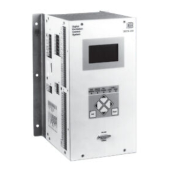
- Page 1 INSTRUCTION MANUAL DIGITAL EXCITATION CONTROL SYSTEM DECS-200 Digital Excitation Control System DECS-200 Null Internal Pre- Limits Balance Tracking Position Lower Upper Edit Reset RS-232 COM 0 P0003-26 06/04/01 Publication: 9360100990 Revision: F 08/06...
- Page 3 INTRODUCTION This instruction manual provides information about the operation and installation of the DECS-200 Digital Excitation Control System. To accomplish this, the following information is provided: • General Information and Specifications • Controls and Indicators • Functional Description • Installation •...
- Page 4 August 2006 CONFIDENTIAL INFORMATION of Basler Electric, Highland Illinois, USA. It is loaned for confidential use, subject to return on request, and with the mutual understanding that it will not be used in any manner detrimental to the interest of Basler Electric.
- Page 5 REVISION HISTORY The following information provides a historical summary of the changes made to the DECS-200 hardware, firmware, and software. The corresponding revisions made to this instruction manual (9360100990) are also summarized. Revisions are listed in chronological order. Hardware Version and Date Change •...
- Page 6 • Section 6 : Added/changed BESTCOMS screens and DECS-200 settings to accommodate changed BESTCOMS screens and new DECS-200 settings. • Section 7 : Added/revised Modbus register tables to accommodate new DECS-200 settings. • Removed expired patent information from Section 1.
- Page 7 Section 2 • Human-Machine Interface....................... 2-1 Section 3 • Functional Description......................3-1 Section 4 • Installation ..........................4-1 Section 5 • BESTCOMS Software......................5-1 Section 6 • Setup ............................6-1 Section 7 • Modbus™ Software......................... 7-1 Section 8 • Maintenance..........................8-1 DECS-200 Introduction...
- Page 8 This page intentionally left blank. Introduction DECS-200...
-
Page 9: Table Of Contents
Operating Power..........................1-2 Control Power ............................. 1-2 Sensing ............................... 1-3 Excitation Limiters..........................1-3 External Tracking and Transfer Between DECS-200 Units (Optional)..........1-3 Internal Tracking Between DECS-200 Operating Modes..............1-3 Communication With a PC........................1-3 MODEL AND STYLE NUMBER DESCRIPTION ................... 1-3 Sample Style Number......................... - Page 10 This page intentionally left blank. General Information DECS-200...
-
Page 11: Section 1 • General Information
Programmability of system parameters and regulation settings enables the DECS-200 to be used in a wide range of applications and provides greater flexibility in excitation system optimization. The DECS-200 can accommodate generator exciter field requirements up to 15 Adc continuously in 32, 63 or 125 Vdc applications with one model. -
Page 12: Application
If power supply option C (120/125 Vac/Vdc) is selected, a redundant power source can be used with the DECS-200. (See Figure 1-1.) In this configuration, if one of the two sources fails, the other source will continue to supply DECS-200 operating power. If power supply option L (24/48 Vdc) is selected, no redundant power source is available. -
Page 13: Sensing
The model number and style number describe the options included in the DECS-200 and appear on a label attached to the side of the case. Upon receipt of a DECS-200 unit, be sure to check the style number against the requisition and packing list to ensure that they agree. -
Page 14: Sample Style Number
Sample Style Number The style number identification chart (Figure 1-2) defines the electrical characteristics and operational features included in the DECS-200. For example, if the style number were DECS-200-1L, the device would have the following characteristics and features. DECS-200 -- Digital Excitation Control System... -
Page 15: Generator Voltage Sensing
Front panel DB-9 connector Com 1: Right-side panel DB-9 connector Com 2: Left-side panel screw terminals (A40, A41, A42) Parameters Baud: 1200 to 19200 Data Bits: Parity: None Stop Bits: 1 (Com 0, Com 1) or 2 (Com 2) DECS-200 General Information... -
Page 16: Contact Inputs
Temperature Drift: ±0.5% for a 0 to 50°C change V/Hz Characteristic: Slope from 0 to 3 PU is adjust-able in 0.1 PU increments. Voltage regulation error is within ±2.0% of the nominal voltage. Response Time: <1 cycle General Information DECS-200... -
Page 17: Parallel Compensation
0 to 100% or <1 Adc field current <45 Hz and >70 Hz generator frequency Generator Undervoltage Protection Pickup Range: 0 to 30 kVac Increment: 1.0 Vac Time Delay Range: 0.5 to 60 s Increment: 0.1 s DECS-200 General Information... -
Page 18: Generator Overvoltage Protection
Medium Current Level Pickup Range: 0 to 20.0 Adc Pickup Increment: 0.1 Adc Time Range: 0 to 120 s Time Increment: Low Current Level Pickup Range: 0 to 15 Adc Pickup Increment: 0.1 Adc Time Range: continuous General Information DECS-200... -
Page 19: Off-Line Overexcitation Limiting
0 to 31 Adc Accuracy: ±0.15 A or ±1.0% (whichever is greater) Power Factor Range: –0.5 to +0.5 PF Accuracy: <0.02 PF Real Power and Reactive Power Range: 0 to 200% of nominal Accuracy: <1.0% of nominal DECS-200 General Information... -
Page 20: Sequence Of Event Recording (Ser)
UL recognized per standard 508, UL file number E90735. CSA Certification Certified per CSA Standard CAN/CSA-C22.2 Number 14, CSA File Number LR23131. CE Compliance The DECS-200 meets the criteria set forth by the following standards: EN 50081-2 Electromagnetic compatibility (EMC) emissions standard: EN 55011, Level A. EN 50082-2... - Page 21 Radio Frequency Conducted EN 61000-4-6, Level A/IEC 1000-4-6 Power Frequency Magnetics EN 61000-4-8, Level A/IEC 1000-4-8 DECS-200 General Information 1-11...
- Page 22 This page intentionally left blank. 1-12 General Information DECS-200...
- Page 23 Figure 2-10. System Parameters Menu Branch (Part 3 of 3) ..............2-20 Figure 2-11. General Settings Menu Branch ................... 2-21 Tables Table 2-1. DECS-200 HMI Component Descriptions ................2-2 Table 2-2. Front Panel Setting Parameters ....................2-4 Table 2-3. Settings Accessible with Setpoint Access Level ..............2-8 Table 2-4.
- Page 24 This page intentionally left blank. Human-Machine Interface DECS-200...
-
Page 25: Section 2 • Human-Machine Interface
Menu screens are viewed and settings are changed by operating the front panel pushbuttons. Active conditions are annunciated by the front panel LEDs. The RS-232 connector (Com 0) enables communication between the DECS-200 and a PC operating BESTCOMS software. -
Page 26: Menu Navigation
LCD. Backlit liquid crystal display is 64 by 128 pixels in size and serves as the primary source of information from the DECS-200. Displays operations, setpoints, loop gains, metering, protection functions, system parameters, and general settings. Pre-Position LED. Lights at the predefined, pre-position setpoint of the active mode. -
Page 27: Changing Settings
Edit Session Timeout .) If this period of inactivity occurs during an edit session, any changes made are saved in nonvolatile memory and will be used or continue to be used by the DECS-200. At this time, both edit access and security access are terminated. CAUTION... -
Page 28: Table 2-2. Front Panel Setting Parameters
OEL Kg 1,000.0 UEL Ki 1,000.0 10.0 UEL Kg 1,000.0 SCL Ki 1,000.0 10.0 SCL Kg 1,000.0 PF Ki 1,000.0 120.0 PF Kg 1,000.0 Var Ki 1,000.0 0.01 120.0 Var Kg 1,000.0 0.01 1.00 Voltage Matching Kg 1,000.0 Human-Machine Interface DECS-200... - Page 29 Off-Line OEL Low Limit 0.0 A 15 A 0.1 A 1.0 A Off-Line Takeover OEL 0.0 A 15.0 A 0.1 A 0.0 A Max. Current Off-Line Takeover OEL 0.0 A 30.0 A 0.1 A 0.0 A High Current DECS-200 Human-Machine Interface...
- Page 30 5.00 s 50 ms 0.10 s Field Overvoltage On, Off Field Overcurrent On, Off Stator Undervoltage On, Off 7.5.2 Stator Overvoltage On, Off Underfrequency On, Off Overexcitation Limit On, Off Underexcitation Limit On, Off FCR Mode On, Off Human-Machine Interface DECS-200...
- Page 31 FCR Prep Mode Maintain, Release Release Var Prep Mode Maintain, Release Release PF Prep Mode Maintain, Release Release 7.8.1 Soft Start Level Soft Start Time 7,200 s 7.9.1 Internal Track rate 1.0 s 80 s 0.1 s 20.0 s DECS-200 Human-Machine Interface...
-
Page 32: Password Protection
Passwords are not case sensitive; the DECS-200 will accept a correct password consisting of uppercase or lowercase letters. There are two levels of access: global and setpoint. Global access grants the user the right to change any editable setting through the front panel. -
Page 33: Metering Screen
DECS-200 units are delivered with the global and setpoint passwords set at decs2. When a password is entered, software first checks for a match between the entered password and the global password. Because the two passwords are the same, global access is always granted. This means that in order to allow setpoint access only, the global and setpoint passwords must be changed so that they are not the same. -
Page 34: Setpoint Field
Mode Message Field The bottom of the metering screen contains the mode message field which displays a message indicating the DECS-200’s current mode of operation. Alarm Annunciation Field The alarm annunciation field, located directly below the metering fields, remains blank during normal operating conditions. -
Page 35: Menu Tree
LCD. If the DECS-200 is using the user-defined values previously set at STAB SET # 21 and a STAB SET # of 1 to 20 is saved, the user-defined values are lost. The next time that user-defined values for STAB SET # 21 are required, they must be manually entered and then saved. - Page 36 These numbers are reference numbers to the screens in the menu tree. A letter at the upper right corner (G, S, and N) indicates the security access level (global, setpoint and not applicable) required to edit that screen. Figure 2-2.Operating Menu Branch 2-12 Human-Machine Interface DECS-200...
- Page 37 Figure 2-3. Setpoint Menu Branch DECS-200 Human-Machine Interface 2-13...
- Page 38 Figure 2-4. Loop Gains Menu Branch 2-14 Human-Machine Interface DECS-200...
- Page 39 Figure 2-5. Metering Menu Branch DECS-200 Human-Machine Interface 2-15...
- Page 40 Figure 2-6. Protection Menu Branch 2-16 Human-Machine Interface DECS-200...
- Page 41 Figure 2-7. Limiters Menu Branch DECS-200 Human-Machine Interface 2-17...
- Page 42 Figure 2-8. System Parameters Menu Branch (Part 1 of 3) 2-18 Human-Machine Interface DECS-200...
- Page 43 Figure 2-9. System Parameters Menu Branch (Part 2 of 3) DECS-200 Human-Machine Interface 2-19...
- Page 44 Figure 2-10. System Parameters Menu Branch (Part 3 of 3) 2-20 Human-Machine Interface DECS-200...
- Page 45 Figure 2-11. General Settings Menu Branch DECS-200 Human-Machine Interface 2-21...
-
Page 46: Front Panel Operation
FRONT PANEL OPERATION The following paragraphs describe the settings and adjustments that are available via the DECS-200 front panel. They are grouped into eight main categories which include: operating modes, setpoints, loop gains, metering, protection, limiters, system parameters, and general settings. -
Page 47: Loop Gains
1.58 200.40 122.10 103.800 10.0 1.67 203.20 118.40 110.100 10.5 1.75 205.70 114.80 116.400 Screen: \GAIN\REG GAIN2 (3.2) AVR Kg - loop gain used in AVR mode FCR Kg - loop gain used in FCR mode DECS-200 Human-Machine Interface 2-23... -
Page 48: Controller Gains
LOSS FIELD - enables and disables loss of field protection Screen: \PROT\PROT_LEVL (5.4) FIELD OV - field overvoltage threshold FIELD OC - field overcurrent base value (100%) STATOR OV - generator output overvoltage threshold STATOR UV - generator output undervoltage threshold 2-24 Human-Machine Interface DECS-200... -
Page 49: Limiters
Off-line overexcitation limiter (summing point) settings. OEL HI LIM - off-line overexcitation limiter high current threshold HI LIM TIME - off-line overexcitation limiter high current time delay OEL LO LIM - off-line overexcitation limiter low current threshold DECS-200 Human-Machine Interface 2-25... -
Page 50: System Parameters
GEN PT PRI - generator sensing transformer primary voltage rating GEN PT SEC - generator sensing transformer secondary voltage rating BUS PT PRI - bus sensing transformer primary voltage rating BUS PT SEC - bus sensing transformer secondary voltage rating 2-26 Human-Machine Interface DECS-200... - Page 51 CRSS I GAIN - cross current compensation input gain Screen: \CNFG AUX Gains (7.4.2) The auxiliary input allows an analog signal to be externally applied to the DECS-200 to modify the operating setpoint. The amount of change that may be induced is proportional to the magnitude of the signal and the input gain.
- Page 52 AT LO LIMIT - assignment of setpoint at low limit annunciation to output relay 3 AT HI LIMIT - assignment of setpoint at high limit annunciation to output relay 3 BELOW 10 HZ – assignment of generator frequency below 10 hertz annunciation to output relay 3 2-28 Human-Machine Interface DECS-200...
-
Page 53: General Settings
COM2 ADDR - device address COM2 DELAY - response delay time PARITY - parity: NONE, ODD, or EVEN STOP BITS - number of stop bits: 1 or 2 Screen: \SETUP\CONTRAST (8.2) Front panel LCD contrast setting DECS-200 Human-Machine Interface 2-29... - Page 54 Screen: \RTC\CLK_FORMAT (8.3.1) TIME FORMAT - selects the format for displaying time on Screen 8.3 DST FORMAT - selects the DECS-200 RTC for day light savings time DATE FORMAT - selects the format for displaying the date on Screen 8.3...
- Page 55 Exciter Diode Monitor Settings......................3-9 SOFT START ............................3-9 LIMITER FUNCTIONS ......................... 3-10 Underfrequency Limiter ........................3-10 Volts per Hertz Ratio Limiter......................3-11 Overexcitation Limiter (OEL) ......................3-11 Summing Point OEL........................3-11 Takeover OEL ..........................3-12 On-Line/Off-Line OEL Options ...................... 3-12 DECS-200 Functional Description...
- Page 56 Figure 3-8. Inverse Time Characteristic for Takeover-Style OEL............3-12 Figure 3-9. Custom Five-Point Curve ...................... 3-13 Figure 3-10. Stator Current Limiting......................3-13 Figure 3-11. Data Record Example ......................3-16 Tables Table 3-1. 52L/M and 52J/K Truth Table (Option 1, Default Settings) ............3-3 Functional Description DECS-200...
-
Page 57: Section 3 • Functional Description
SECTION 3 • FUNCTIONAL DESCRIPTION INTRODUCTION This section illustrates and describes the functional capabilities of the DECS-200. FUNCTION BLOCK DESCRIPTIONS The function blocks of the DECS-200 are illustrated in Figure 3-1 and described in the following paragraphs. FLASH EEPROM MEMORY... -
Page 58: Contact Input Circuits
DECS-200 is in AVR mode, this input has no effect. FCR (Field Current Regulation) This input accepts a momentary contact closure that places the DECS-200 in FCR mode. Once the unit is in FCR mode, this input has no effect. The FCR input takes precedence over the AVR input. -
Page 59: K (Var/Power Factor Enable)
Field current (internal) Generator Voltage Sensing Ranges The ac voltage sensing range of the DECS-200 is split into four operating ranges: 120 volts nominal, 240 volts nominal, 480 volts nominal, and 600 volts nominal. The range selection is the same for generator and bus voltages and is based on the secondary VT voltage for the generator voltage sensing. -
Page 60: Bus Voltage
4 to 20 milliamperes. When the current input mode is selected, the input current (4 to 20 milliamperes) is converted by the DECS-200 to –5 to +5 Vdc voltage signal. The following equation is used when converting current signals to voltage signals. -
Page 61: Analog-To-Digital Converter (Adc)
+5 Vdc, ±12 Vdc, and +24 Vdc for the DECS-200 internal circuitry. When dual power sources are used, an isolation transformer is required for the ac input. Analog-to-Digital Converter (ADC) All analog input signals are brought to the input of the 12-bit ADC. Each input signal is sampled at a rate that is controlled by the digital signal processor (DSP). -
Page 62: Watchdog Output
• Software in the DECS-200 stops executing normally On/Off Output The On/Off (ON/OF) output indicates the enabled/disabled status of the DECS-200. the On/Off output closes when the DECS-200 is enabled and opens when the DECS-200 is disabled. Communication The RS-232 port (Com 0), located on the front panel, is dedicated for communication with a PC running BESTCOMS software. -
Page 63: Protection Functions
RAM is volatile and serves as temporary storage for data. EEPROM is nonvolatile and stores the settings and configuration. Protection Functions Eight protection functions are available in the DECS-200: • • Field overvoltage Loss of sensing • •... -
Page 64: Generator Overvoltage
Exciter Diode Monitor (EDM) The DECS-200 monitors the output of the brushless exciter power semiconductors through the exciter field current and protects against both open and shorted diodes in the exciter bridge. When implementing the EDM, it is imperative that the user know and specify the number of poles for the exciter armature and the number of poles for the generator rotor. -
Page 65: Exciter Diode Monitor Settings
Vary the generator voltage from minimum to maximum voltage while monitoring the EDM OD and EDM SD % ripple on the DECS-200 HMI metering screen. Record the highest value for each. See Section 2, Human-Machine Interface for more details on displaying metering quantities. -
Page 66: Limiter Functions
Figure 3-3. Soft Start Voltage Reference LIMITER FUNCTIONS DECS-200 limiter functions include an underfrequency limiter, V/Hz ratio limiter, overexcitation limiter, underexcitation limiter, and a stator current limiter. Underfrequency Limiter When the generator frequency drops below the Corner Frequency corner frequency for the underfrequency slope... -
Page 67: Volts Per Hertz Ratio Limiter
The volts per hertz ratio limiter prevents the regulation setpoint from exceeding the volts per hertz ratio that is prescribed by the slope setting of the DECS-200 as stated in the previous paragraphs. This feature is also useful for other potentially damaging system conditions such as a... -
Page 68: Takeover Oel
OEL settings. In this case, the on-line OEL settings are active to limit excessive excitation current. This option also eliminates the need for the DECS-200 to operate in Droop mode when applied in a single unit application. Therefore, voltage should not droop as reactive load increases. -
Page 69: Underexcitation Limiter
The stator current limiter (SCL) senses the level of stator current and limits it to prevent stator overheating. The SCL operates in all modes except FCR. In FCR mode, the DECS-200 only announces that a stator overcurrent condition exists; it does not provide current limiting. -
Page 70: Droop And Line-Drop Compensation
R is assumed to be zero. For LDC, the above equation becomes: DATA LOGGING AND REPORTING DECS-200 data logging and reporting features include a sequence of events recorder that records up to eight oscillography records. Sequence of Events Reporting A sequence of events recorder monitors the internal and external status of the DECS-200. -
Page 71: Oscillography
Oscillography The data recording function of the DECS-200 can record up to eight oscillography records. Oscillography records recorded by the DECS-200 use the IEEE Standard Common Format for Transient Data Exchange (COMTRADE). Each record is time and date stamped. After eight records have been recorded, the DECS-200 begins recording the next record over the oldest record. - Page 72 Figure 3-11. Data Record Example 3-16 Functional Description DECS-200...
- Page 73 Figure 4-2. Panel Drilling Diagram, Projection Mount ................4-3 Figure 4-3. Escutcheon Plate Dimensions....................4-4 Figure 4-4. Panel Cutting and Drilling Dimensions, Panel Mount..............4-5 Figure 4-5. DECS-200 to DECS-200 Communication Connections............4-6 Figure 4-6. DECS-200 Left-Side Terminals ....................4-7 Figure 4-7. Typical Cross-Current Compensation Connections ..............4-10 Figure 4-8.
- Page 74 This page intentionally left blank. Installation DECS-200...
-
Page 75: Section 4 • Installation
Two DECS-200 mounting configurations are possible: projection mounting and panel mounting. The panel drilling diagram for projection mounting of a DECS-200 is shown in Figure 4-2. Panel mounting of a DECS-200 is possible with the optional escutcheon plate (part number 9360107100). Escutcheon plate dimensions are shown in Figure 4-3. - Page 76 Figure 4-1. Overall Dimensions Installation DECS-200...
- Page 77 Figure 4-2. Panel Drilling Diagram, Projection Mount DECS-200 Installation...
- Page 78 Figure 4-3. Escutcheon Plate Dimensions Installation DECS-200...
- Page 79 Figure 4-4. Panel Cutting and Drilling Dimensions, Panel Mount DECS-200 Installation...
-
Page 80: Connections
Terminations for DECS-200 connections are located on the right-hand panel, the front panel, and the left- hand panel. Right-Hand Panel Connections Right-hand panel terminations consist of a nine-pin, female, D-type connector (Com 1) that is used for communication with a second DECS-200 unit when operating in a redundant system. -
Page 81: Front Panel Connections
Front panel terminations consist of a nine-pin, female, D-type connector (Com 0) that is intended for short-term, RS-232 serial communication with a PC operating BESTCOMS software. Refer to Section 5, BESTCOMS Software for information about using BESTCOMS to communicate with the DECS-200. Left-Hand Panel Connections Left-hand panel terminations consist of screw compression terminals. -
Page 82: Control Power
DECS-200 units have two sets of power terminals. One set receives dc control power and the other set receives ac control power. A DECS-200 with a style number of XL accepts nominal dc control power of 24 or 48 Vdc. The ac control power input of a style XL DECS-200 is not used. -
Page 83: Generator Current Sensing
5 Aac sensing range on the DECS-200 cross-current input. The 1 Ω resistor is a typical value that can be used to set the burden. (Ensure that the resistor power rating is adequate for the installation.) Like the generator current sensing input, the cross-current input has two terminals to accommodate 1 Aac or 5 Aac CTs. -
Page 84: Accessory Input
Negative side of voltage accessory input Contact Inputs The DECS-200 has 11 fixed-function contact inputs. Each contact input supplies an interrogation voltage of 12 Vdc and accepts dry switch/relay contacts or open-collector PLC outputs. Open-collector devices connected to the contact inputs must be compatible with the 12 Vdc interrogation voltage, be capable of conducting a minimum of 5 mAdc, and have off-state leakage current no greater than 100 μAdc. -
Page 85: Output Contacts
Field Output The DECS-200 output is capable of supplying 15 Adc of continuous excitation current to a field with no less than 2.13 ohms of resistance (at 32 Vdc), 4.2 ohms of resistance (at 63 Vdc), or 8.3 ohms of resistance (at 125 Vdc). - Page 86 DECS-200 Com 2 DECS-200 Com 2 4000' MAX. DECS-200 Com 2 = Optional terminating resistor (120 O typical) Figure 4-8. RS-485 DB-37 to DECS-200 Typical Connections Connections for a typical DECS-200 application are illustrated in Figure 4-9. 4-12 Installation DECS-200...
- Page 87 Figure 4-9. Typical Connections DECS-200 Installation 4-13...
- Page 88 This page intentionally left blank. 4-14 Installation DECS-200...
- Page 89 SECTION 5 • BESTCOMS SOFTWARE....................5-1 INTRODUCTION ............................ 5-1 INSTALLATION ............................5-1 Operating Requirements........................5-1 Installing BESTCOMS ........................5-1 Connecting the DECS-200 and PC ....................5-1 STARTING BESTCOMS ........................5-1 Establishing Communication ......................5-1 Configuring the Communication Ports....................5-2 Configuring the Real-Time Clock......................5-2 Assigning Identification Labels ......................
- Page 90 Figure 5-34. Metering Screen, Operation Tab ..................5-31 Figure 5-35. Metering Screen, Alarm/Status Tab ..................5-32 Figure 5-36. PID Window......................... 5-34 Tables Table 5-1. Predefined Stability Setting Groups..................5-16 Table 5-2. Data Log Report Parameter Triggers ..................5-30 Table 5-3. 52J/K and 52L/M Logic ......................5-31 BESTCOMS Software DECS-200...
-
Page 91: Section 5 • Bestcoms Software
Installing BESTCOMS 1. Insert the DECS-200 CD-ROM into the PC CD-ROM drive. 2. When the DECS-200 Setup and Documentation CD Menu appears, click the Install button for BESTCOMS-DECS200. The BESTCOMS setup utility automatically installs BESTCOMS. When BESTCOMS is installed, a Basler Electric folder is added to the Windows program menu. This folder is accessed by clicking the Start button and pointing to Programs. -
Page 92: Configuring The Communication Ports
4). To access the Set Real Time Clock screen, click Configure on the menu bar and click Real Time Clock. The DECS-200 date and time are set by altering the date and time fields or by retrieving the PC date and time and then sending the values to the DECS-200. -
Page 93: Assigning Identification Labels
DECS-200 by clicking the SendToDECS button or by clicking Communications on the menu bar and then clicking Send To DECS. A single setting change can be sent to the DECS-200 by pressing the keyboard Enter key. Functions controlled by option buttons or checkboxes are immediately sent to the DECS-200 when the option button or checkbox is selected. -
Page 94: System Settings
Version Numbers. These two read-only fields display the version of BESTCOMS software and the firmware version of the DECS-200 connected to the PC operating BESTCOMS. In order for the DECS- 200 firmware version to be displayed, communication must be established between BESTCOMS and the DECS-200. - Page 95 External Tracking, Enable/Disable. Enables or disables tracking of a second DECS-200’s setpoint. External Tracking, Delay. Determines the time delay between a transfer to a second DECS-200 and start of tracking of the second DECS-200 setpoint. A setting of 0 to 8 seconds may be entered in 0.1 second increments.
- Page 96 External Tracking, Traverse Rate. Determines the amount of time required for the DECS-200 to traverse (cross) the full setting range of a second, active DECS-200. A setting of 1 to 80 seconds may be entered in 0.1 second increments. Rated Data Rated Data tab functions are shown in Figure 5-9 and described in the following paragraphs.
- Page 97 Auxiliary Input, Summing Type. Selects either Inner Loop or Outer Loop as the summing type. When Inner Loop is selected, the operating mode is either AVR of FCR. When Outer Loop is selected, the operating mode is either var or power factor. DECS-200 BESTCOMS Software...
-
Page 98: Setting Adjustments
Automatic Voltage Regulator, Traverse Rate (sec). Determines the time required to adjust the AVR setpoint from the minimum value to the maximum value of the adjustment range. A setting of 10 to 200 seconds may be entered in 1 second increments. BESTCOMS Software DECS-200... - Page 99 Maintain. The setting range is identical to the AVR Setpoint setting range. If sensing step-down transformers are being used, primary voltage should be entered. Automatic Voltage Regulator, Preposition Mode. Determines whether or not the DECS-200 will respond to further setpoint change commands once the operating setpoint is driven to the pre-position value. If Maintain mode is selected, further setpoint changes are ignored.
- Page 100 The setting range is identical to the PF Setpoint setting range. Power Factor Control, Preposition Mode. Determines whether or not the DECS-200 will respond to further setpoint change commands once the operating PF setpoint is driven to the pre-position value. If Maintain mode is selected, further setpoint changes are ignored.
- Page 101 Figure 5-15. System Settings Screen, OEL Type Tab OEL Limiter Style. Selects either the summing-point type of overexcitation limiter or the takeover-type of overexcitation limiter. OEL Setting Selection Option. Selects the on-line and off-line OEL settings for various 52J/K and 52L/M contact statuses. DECS-200 BESTCOMS Software 5-11...
- Page 102 (open 52L/M contact) as the speed of the machines is increased. However, both machines need active, off-line overexcitation limiting protection. Option 3 activates the on-line OEL at all times. This configuration enables the DECS-200 to operate in AVR mode (stand-alone application) without restriction from the off-line OEL settings. The active on-line OEL is able to limit excitation current if needed.
- Page 103 UEL Settings, UEL Curve Type Selection. Selects either a user-configured or internally-configured underexcitation limiting curve. Selecting “Customized” enables the user to create a custom UEL curve that matches specific generator characteristics. When “Internal” is selected, the DECS-200 automatically DECS-200 BESTCOMS Software...
- Page 104 A setting of 0 to 60 seconds may be entered in 1 second increments. Stator Current Limiter, Low SCL Current Level. Configures the low-level current setpoint for the stator current limiter. A setting of 0 to 66,000 Aac may be entered in 1 Aac increments. 5-14 BESTCOMS Software DECS-200...
-
Page 105: Control Gain
Stability Range. Entering a value from 1 to 20 selects one of 20 predefined stability setting groups for exciter field applications. Table 5-1 lists the stability settings for each of the 20 predefined groups. Entering 21 enables the PID function and allows the user to optimize the stability settings. The PID DECS-200 BESTCOMS Software 5-15... - Page 106 KP. A setting of 0 to 1,000 may be entered in 0.1 increments. AVR/FCR, Integral Gain KI. Selects the integral constant (KI) stability parameter. The DECS-200 provides an output value that is equivalent to KI multi-plied by the integral of the error between the voltage setpoint and the actual generator output voltage.
-
Page 107: Analysis
VAR/PF, PF Loop Gain Kg. Sets the coarse loop-gain level of the PID algorithm for power factor control. A setting of 0 to 1,000 may be entered in 0.1 increments. SCL, Integral Gain KI. Adjusts the rate at which the DECS-200 limits stator current. A setting of 0 to 1,000 may be entered in 0.1 increments. - Page 108 System frequency below 10 Hz • Underexcitation limiting • Underfrequency or volts per hertz Figure 5-21. Analysis Screen, AVR Tab FCR tab settings are illustrated in Figure 5-22 and described in the following paragraphs. Figure 5-22. Analysis Screen, FCR Tab 5-18 BESTCOMS Software DECS-200...
- Page 109 Field Current Step Response, Increment of FCR Setpoint. Sets the current step size that the DECS-200 uses when incrementing the field current setpoint. A setting of 0 to 10% may be entered in 1% increments. A button adjacent to this setting is clicked to increment the field current setpoint. A read-only field indicates the field current setpoint that will be achieved when the increment button is clicked.
- Page 110 “Index 1”. Upon release of the button, the new var value setting is sent to the DECS-200 as the reactive power setpoint for the var regulator. If the specified var value is outside the range limit, a dialog box appears and shows the acceptable values for the step response.
-
Page 111: Protection/Relay
“Index 1”. Upon release of the button, the new power factor value is sent to the DECS-200 and the PF setpoint for the power factor regulator. If the specified PF value is outside the range limit, a dialog box appears and shows the acceptable values for the step response. - Page 112 LEDs.) If programmed for the overvoltage function, one or more of the three programmable output relays are actuated. A setting of 0 to 30,000 Vac may be entered in 1 Vac increments. 5-22 BESTCOMS Software DECS-200...
- Page 113 LED lights. (See the Alarm/Status tab of the Metering screen or the Analysis screen for the detailed alarm LED signals.) Any of the three programmable DECS-200 output relays can be programmed to annunciate a loss of field condition. A setting of 0 to 3,000,000 kvar may be entered in1 kvar increments.
- Page 114 Setpoint Limit. A programmable output can be configured to close when the active setpoint reaches the upper limit or lower limit. FCR Mode. Enabling this setting closes the programmable output when the DECS-200 is operating in FCR (Manual) mode. Limit. A programmable output can be configured to close when the following limits are reached: overexcitation, stator current, underfrequency or volts per hertz, and underexcitation.
-
Page 115: Data Log
Screens on the menu bar and click Data Log. Log Setup/Sequence Of Events Log Setup/Sequence of Events tab settings are illustrated in Figure 5-29 and described in the following paragraphs. Figure 5-29. Data Log Screen, Log Setup/Sequence of Events Tab DECS-200 BESTCOMS Software 5-25... - Page 116 Display the Following Events. The event type displayed in the Event List is controlled by selection made here. Available event-type selections are New, All New and Old, New Alarm, New I/O, and New Mode. Print/Save Report. Clicking this button allows the report to be saved as a text file or printed. 5-26 BESTCOMS Software DECS-200...
- Page 117 Print/Save Report. Clicking this button allows a report to be either saved as a text file or printed. Print/Save Record. Clicking this button allows a record to be either saved as a text file or printed. Logic Triggers Logic Triggers tab settings are illustrated in Figure 5-32 and described in the following paragraphs. DECS-200 BESTCOMS Software 5-27...
- Page 118 Figure 5-32. Data Log Screen, Logic Triggers Tab Contact Inputs. This area of the Logic Triggers tab lists the available DECS-200 contact inputs that can be selected to trigger a data log report. The following contact inputs are available for triggering a data log report: •...
- Page 119 (On) or disabled (Off). Selecting No Trigger disables a voltage matching trigger. System Status, Auto Tracking. Enables a data log report to be triggered when the DECS-200 is functioning as the primary controller or the secondary controller in a redundant DECS-200 system.
-
Page 120: Metering
Operation tab parameters and controls are illustrated in Figure 5-34 and described in the following paragraphs. DECS-200 BESTCOMS software provides real-time monitoring of the following data. This data is refreshed approximately once every second. Metering is enabled or disabled through the pull-down menu or by clicking the Metering button. - Page 121 If the control mode is FCR and Var of PF mode is selected, that selection will be ignored by the DECS-200. Even if the Var or PF indicator turns on, the system will not be in those modes unless the DECS-200 52J/K input is open.
-
Page 122: Saving, Printing, And Opening Files
A settings file can also be printed from BESTCOMS. Saving Files A DECS-200 settings file is saved through a Save As dialog box. The Save As dialog box is accessed by using any of three methods: 5-32... -
Page 123: Printing Files
If you select Yes, then 17 blocks of DECS-200 setting data are sent to the DECS-200 block by block. Please wait until all 17 blocks of data have been transferred. When power is next applied to the DECS- 200 unit, the previously saved settings will become the current settings. -
Page 124: Pid Calculations Based On Input Values
0.83 seconds. The calculated KP is 155.47, KI is 138.72, KD is 48, and Kg is 1. PID parameters can be directly removed from, added to, or modified in the PID List Data. PID parameters may also be saved into a file (pidlist.dat). 5-34 BESTCOMS Software DECS-200... -
Page 125: Adding To Pid List
Click the Get from a list button and the listed record input and output data displays in the text boxes. TERMINATING COMMUNICATION Communication between BESTCOMS and the DECS-200 is terminated by clicking Communications on the menu bar and clicking Close Comm Port. DECS-200... - Page 126 This page intentionally left blank. 5-36 BESTCOMS Software DECS-200...
- Page 127 Figure 6-19. Insufficient Proportional Gain ....................6-16 Figure 6-20. Prolonged Instability ......................6-16 Figure 6-21. Insufficient Derivative Gain....................6-17 Figure 6-22. Final Solution Step Response ..................... 6-17 Tables Table 6-1. Generator and Field Ratings ....................6-1 Table 6-2. Programmable Output Function Assignments................6-12 DECS-200 Setup...
- Page 128 This page intentionally left blank. Setup DECS-200...
-
Page 129: Section 6 • Setup
The following equipment is required to perform the procedures presented here: • Two-channel chart recorder or the DECS-200’s oscillography. First channel measures the generator voltage at DECS-200 terminals A1 (E1) and A3 (E3). Second channel measures the field voltage at DECS-200 terminals C5 (F+) and C6 (F–). •... - Page 130 Enter the system PT and CT ratings and configure the internal and external tracking settings illustrated in Figure 6-2. Figure 6-2. System Data Tab Enter the generator PT primary voltage rating................________ Enter the generator PT secondary voltage rating ................. ________ Enter the generator CT primary current rating................________ Setup DECS-200...
- Page 131 Enable or disable external tracking (applies only to redundant DECS-200 systems) ....________ Set the external tracking delay (applies only to redundant DECS-200 systems) ......________ Set the external tracking traverse rate (applies only to redundant DECS-200 systems) ..... ________ Rated Data Enter the generator and exciter field ratings and exciter-to-generator pole ratio settings illustrated in Figure 6-3.
-
Page 132: Setting Adjustments Screen
Enter the field current setpoint for FCR mode ................________ Enter the minimum desired FCR mode setpoint, expressed as a percent of nominal ....________ Enter the maximum desired FCR mode setpoint, expressed as a percent of nominal ....________ Enter the FCR mode traverse rate....................________ Setup DECS-200... - Page 133 Configure the var mode and power factor mode settings illustrated in Figure 6-7. If var or PF mode is enabled, the setpoint will be active only after transfer occurs into the specific mode because autotracking always forces a null condition to any operating mode. Figure 6-6. Var/PF Tab DECS-200 Setup...
- Page 134 Enter the generator frequency slope for underfrequency protection ..........________ Enter the voltage matching band, expressed as a percent of the rated generator voltage ..________ Enter the ratio (percentage) of the generator PT output to the bus PT output ......________ Setup DECS-200...
- Page 135 OEL Type tab selections are illustrated in Figure 6-8. Figure 6-8. Setting Adjustments Screen, OEL Type Tab Summing-Point OEL If summing-point overexcitation limiting is enabled, configure the off- and on-line OEL settings illustrated in Figure 6-10. Figure 6-9. OEL Summing Tab DECS-200 Setup...
- Page 136 UEL settings can be applied. When internal UEL settings are used, only one data point is required. When customized UEL settings are used, up to five data coordinates may be entered to match a specific generator curve. Figure 6-11 illustrates the settings of the UEL tab. Setup DECS-200...
- Page 137 Figure 6-12. Setting Adjustments Screen, SCL Tab Enter the high-level current setpoint for stator current limiting ............. ________ Enter the duration for high-level stator current limiting ..............________ Enter the low-level current setpoint for stator current limiting............________ DECS-200 Setup...
-
Page 138: Protection/Relay Screen
Enter the protection settings illustrated in Figure 6-14. Only protection functions enabled on the Options tab need to be configured here. Enter the threshold for generator overvoltage protection ............. ________ Enter the time delay for generator overvoltage protection............________ 6-10 Setup DECS-200... - Page 139 Review the excitation system interconnection drawings and verify the relay configurations. Relay logic settings for each of the three DECS-200 programmable outputs are contained on two tabs with identical configuration options. Only the tab for Relays 1 and 2 is illustrated here (Figure 6-15). Table 6-2 lists all of the available functions that can be assigned to the programmable outputs.
- Page 140 Open exciter diode Loss of field Field overvoltage Field overcurrent Sensing input below 10 Hz Shorted exciter diode FCR mode Upper setpoint limit Lower setpoint limit Overexcitation limit Underexcitation limit Underfrequency or V/Hz limit Stator current limit 6-12 Setup DECS-200...
-
Page 141: Off-Line Tests - Turbine Not Spinning
Start/Stop Tests Check the operation of the following start and stop controls. BESTCOMS Metering Screen, Operation tab ................________ DECS-200 front panel........................________ Remote switches........................... ________ With excitation off, check AVR/FCR transfer from the BESTCOMS, the front panel, and remote switches ..........................________... -
Page 142: Control Gain Settings
For off-line tests with the turbine spinning, the generator circuit breaker is open. FCR Mode Initial testing should be conducted in FCR (manual) mode and minimum generated voltage. Place the DECS-200 in FCR mode....................________ Place the Start/Stop switch in the Start position ................________ 6-14... - Page 143 Adjust the PID values until desired performance is achieved. If performance appears stable, repeat step change at 5%......................________ NOTE Assuming Te (exciter field) is known (as applicable for exciter field voltage regulator applications), increasing Kg will decrease the response time of the generator. See Figure 6-21. DECS-200 Setup 6-15...
- Page 144 Figure 6-19. Insufficient Proportional Gain Figure 6-23 demonstrates that the terminal voltage has prolonged instability after a voltage step change because there is too much integral gain (I). Integral gain value needs to be decreased. Figure 6-20. Prolonged Instability 6-16 Setup DECS-200...
-
Page 145: Excitation Performance Evaluation
To speed performance in the following test, you may increase the OEL gain (KI and Kg terms). On the AVR/FCR tab of the BESTCOMS Setting Adjustments screen, adjust the AVR setpoint to 110% of the rated output. (the AVR Max setting should remain at 105%.) ......________ DECS-200 Setup 6-17... -
Page 146: Limit And Protection Check
Set the machine kilowatt level at approximately 25% of the machine rating at 0 vars ....________ Check for phase shift at the voltage and current sensing inputs of the DECS-200. The B-phase current should lag the sensed voltage (between E1 and E3) by 90°. If the phase relationship is correct, proceed with testing. - Page 147 Verify that PF Pre-Position mode is disabled or external pre-position contacts are open.... ________ In the following step, be prepared to transfer back to AVR mode if the excitation voltage increases suddenly. Transfer to PF ..........................________ DECS-200 Setup 6-19...
-
Page 148: Conclusion Of Testing
If necessary, increase the PF gain (KI and Kg terms) to decrease the response time. Repeat the test..........................________ Conclusion Of Testing Configure the excitation system with the required parameters. Once satisfactory performance is achieved, save all information to EEPROM. 6-20 Setup DECS-200... - Page 149 Holding Registers for Information Category C15................7-27 Tables Table 7-1. DECS-200 Communication Settings ..................7-2 Table 7-2. Timing Considerations For 10 Character Bits (8 Data Bits + 1 Start Bit + 1 Stop Bit) ..... 7-3 Table 7-3. Supported Exception Response Codes..................7-3 Table 7-4.
- Page 150 Table 7-22. Information Category C12 (Relay Parameters) ..............7-23 Table 7-23. Information Category C13 (Communications Parameters) ..........7-26 Table 7-24. Information Category C14 (Front Panel Metering Configuration Parameters) ..... 7-27 Table 7-25. Information Category C15 (Control System Configuration Parameters Group II) ....7-27 Modbus Communication DECS-200...
-
Page 151: Section 7 • Modbus Communication
Modbus communications use a master-slave technique in which only the master can initiate a transaction called a query. When appropriate, a slave (DECS-200 ) responds to the query. When a Modbus master communicates with a slave, information is provided or requested by the master. -
Page 152: Function Code Field
DECS-200 Modbus performs all of the above functions when a Modbus message has its unique address which is numbered from 1 to 247. DECS-200 also recognizes a broadcast (group) address of 0. Only functions 16 and 8 are recognized as valid for broadcast. The DECS-200 does not send a response message for a broadcast query. -
Page 153: Message Framing And Timing Considerations
When receiving a message, the DECS-200 requires an inter-byte latency of 3.5 character times before considering the message complete. Once a valid query is received, the DECS-200 waits a specified amount of time as specified in the Modbus Response Delay Time Register (48108) before responding. This Register contains a value from 0 to 200 milliseconds. -
Page 154: Detailed Message Query And Response
Data Block byte count and data. The DECS-200 will perform the write when the device address is the same as the DECS-200 remote address or when the device address is 0. A device address is 0 for a broadcast query. -
Page 155: Preset Single Register (Write Single Holding Register)
There are several instances of registers that are grouped together to collectively represent a single numerical DECS-200 data value (i.e., floating point data and 32-bit integer data). A query to write a subset of such a register group will result in an error response with Exception Code “Illegal Data Address”. -
Page 156: Loop Back Diagnostic Test (Fc= 8) With Diagnostic Sub-Function, Return Query Data
If the query is a broadcast (device address of 0), no response message is returned. If the DECS-200 receives this query while in the listen only mode (LOM), no response message is generated. Otherwise, a response message identical to the query message is transmitted prior to the communications restart. -
Page 157: Generic Types Ui16 And I16
3.38 x 10 It should be noted that an ASCII string is not a DECS-200 generic data type. An ASCII string will be considered as a sequence of “(string length + 1)” data of I8 type, and for its transmission via a Modbus network “(string length + 1)”... -
Page 158: Floating Point (R23_32) Data Format
0100 0010 1111 0110 CAUTION For DECS-200 Modbus, two consecutive holding registers which are mapped to any of the 4-byte generic data types, are considered to be linked together as one atomic, indivisible unit of information which can be read or written by Modbus message only as one entity (that is, one cannot be read or written without the other). -
Page 159: Crc Error Check
DECS-200 MODBUS REGISTER SPACE Modbus Address space from 40000 to 49999 refers to Functions Code 3, 6 and 16. The DECS-200 uses address space from 47001 to 48250 (1250 registers). This address space is divided into 14 areas referred to as information categories. -
Page 160: Decs-200 Register Table
DECS-200 REGISTER TABLE Each data to be transmitted via Modbus network is identified by its holding register(s). The following tables provide the complete list of holding register assignments and descriptions for the DECS-200. There is a separate table for each information category. - Page 161 47045 2nd character of the ASCII string of Boot program version number 3rd character of the ASCII string of Boot program version number 47046 4th character of the ASCII string of Boot Program version number 47047 DECS-200 Modbus™ Communication 7-11...
-
Page 162: Holding Registers For Information Category C2
47261-62 Generator apparent power in kVA R32_23 47263-64 Generator real power in kW R32_23 47265-66 Generator reactive power in kvar R32_23 47267-68 Power factor R32_23 47269-70 Generator frequency in hertz R32_23 47271-72 Bus frequency in Hz R32_23 Modbus™ Communication DECS-200 7-12... - Page 163 Protection status bit flags (0 = clear, 1 = condition present) UI16 b0 = loss of field, b1 = in SCL, b2 – b15 are unassigned Annunciation status bit flags (0 = clear, 1 = condition present) UI16 47307 DECS-200 Modbus™ Communication 7-13...
-
Page 164: Holding Registers For Information Category C3
Generator rated field voltage, adjustable from 1 to 400 Vdc in 1 volt R32_23 47527-28 increments 47529-30 Generator rated field current, adjustable from 0.1 to 9999.0 Adc in R32_23 0.1 amp increments Nominal bus voltage, adjustable from 85 to 500,000 Vac in 1 volt R32_23 47531-32 Modbus™ Communication DECS-200 7-14... -
Page 165: Holding Registers For Information Category C5
Note: Read value of register 47561 is always 0. Virtual toggle switch for changing control mode from comm. port UI16 47562 between AVR and FCR: 0 = no change / 1 = change state. Holding register 47573 contains Control mode status. DECS-200 Modbus™ Communication 7-15... - Page 166 OEL option: 0 = Option 1, 1 = Option 2, 3 = Option 3 UI16 47585 47586 PF/var option status: 0 = Off, 1 = PF, 2 = var UI16 Reserved for future C5 data 47587 to supported defined 47620 Modbus™ Communication DECS-200 7-16...
-
Page 167: Holding Registers For Information Category C6
AVR mode setpoint minimum (in % of rated generator output R32_23 voltage), adjustable from 70 to 100% in 0.1% increments Var mode setpoint minimum (in % of rated generator VA), adjustable R32_23 47659-60 from -100 to 100% in 0.1% increments DECS-200 Modbus™ Communication 7-17... - Page 168 47655-56) x (regs. 47529-30) / 100 AVR minimum setpoint (in volts) = % of nominal x rated gen. R32_23 47701-02 voltage:(regs. 47657-58) x (regs. 47525-26) / 100 47703-04 Var minimum setpoint (in kvar) = % of nominal x rated generator R32_23 Modbus™ Communication DECS-200 7-18...
-
Page 169: Holding Registers For Information Category C7
100% of rated generator voltage in 0.1% increments 47759-60 Loss of sensing level under unbalanced conditions, adjustable from R32_23 0% to 100% of rated generator voltage in 0.1% increments Reserved for future C7 data 47761 to supported defined 47800 DECS-200 Modbus™ Communication 7-19... -
Page 170: Holding Registers For Information Category C8
(in kvar) 47837-38 5th UEL point reactive power value, adjustable from 0 to generator’s R32_23 full rating (in kvar) SCL high limit level, adjustable from 0 to 66,000 A in 0.1 A R32_23 47839-40 increments Modbus™ Communication DECS-200 7-20... -
Page 171: Holding Registers For Information Category C9
AVR mode loop gain (Kg), adjustable from 0 to 1,000 in 0.1 R32_23 increments Var mode loop gain (Kg), adjustable from 0 to 1,000 in 0.01 R32_23 47879-80 increments PF mode loop gain (Kg), adjustable from 0 to 1000 in 0.1 increments R32_23 47881-82 DECS-200 Modbus™ Communication 7-21... -
Page 172: Holding Registers For Information Category C10
47938 47939 Stator undervoltage alarm enable: 0 = disabled / 1 = enabled UI16 47940 Stator overvoltage alarm enable: 0 = disabled / 1 = enabled UI16 47941-42 Reserved R32_23 R32_23 47943-44 Reserved UI16 47945 Reserved Modbus™ Communication DECS-200 7-22... -
Page 173: Holding Registers For Information Category C11
Below 10 Hz, b13 = field overtemperature, b14, b15 are unassigned. 48042 Annunciation enable for Relay 1: 0 = disabled, 1 = enabled b0 = loss UI16 of field, b1 = in SCL, b2-b15 are unassigned Reserved UI16 48043 Reserved UI16 48044 48045 Reserved UI16 DECS-200 Modbus™ Communication 7-23... - Page 174 Reserved UI16 48063 Reserved UI16 48064 48065 Reserved UI16 Reserved UI16 48066 Reserved UI16 48067 48068 Reserved UI16 Reserved UI16 48069 Reserved UI16 48070 48071 Reserved UI16 Reserved UI16 48072 Reserved UI16 48073 48074 Reserved UI16 Modbus™ Communication DECS-200 7-24...
- Page 175 1 = open for normal operation, closed for annunciation Relay 3 output duration for momentary type, adjustable from 2 to 100 UI16 48100 in unity increments (which is 0.1 to 5 s in 0.05 s increments) DECS-200 Modbus™ Communication 7-25...
-
Page 176: Holding Registers For Information Category C13
0x0040 saves C10; 0x0080 saves C11; 0x0100 saves C12; 0x0800 saves C14. (Changes in C13 are automatically saved.) Comm. Port 0, front RS-232, baud rate, selectable to be 1200, 2400, UI16 48162 4800, 9600, or 19200 Modbus™ Communication DECS-200 7-26... - Page 177 Parity,‘E’ = 69 = 0x45 for Even Parity, and ‘N’ = 78 = 0x4E for No Parity Comm. port 2, Rear RS-485, stop bits, selectable to be 1 or 2 48166 DECS-200 polling address (Modbus slave address), selectable from UI16 48167 1 to 247 (slave address)
- Page 178 This page intentionally left blank. Modbus™ Communication DECS-200 7-28...
-
Page 179: Section 8 • Maintenance
DECS-200 Appears Inoperative If the DECS-200 does not power up (no backlighting on front panel display), ensure that the control power applied to the unit is at the correct level. If dc control power is being used, verify that the polarity is correct. - Page 180 If your PF, var, or watt readings are significantly different from the expected readings for a known load, verify that the B-phase current sensing input of the DECS-200 is connected to a CT on phase B and not phases A or C.
- Page 181 ROUTE 143, BOX 269 HIGHLAND, IL 62249 USA http://www.basler.com, info@basler.com PHONE +1 618-654-2341 FAX +1 618-654-2351...
Need help?
Do you have a question about the DECS-200 and is the answer not in the manual?
Questions and answers