
Related Manuals for Basler SCP 250


Summary of Contents for Basler SCP 250
- Page 1 INSTRUCTION MANUAL VAR/POWER FACTOR CONTROLLER SCP 250 Publication: 9 1100 00 99Y Revision: T 01/08...
- Page 3 INTRODUCTION This instruction manual provides information about the operation and installation of the SCP 250 Var/Power Factor Controller. To accomplish this, the following information is provided. • General Information and Specifications • Control Descriptions • Functional Description • Installation Drawings •...
- Page 4 January 2008 CONFIDENTIAL INFORMATION of Basler Electric, Highland Illinois, USA. It is loaned for confidential use, subject to return on request, and with the mutual understanding that it will not be used in any manner detrimental to the interest of Basler Electric.
-
Page 5: Table Of Contents
Figure 4-3. KR-F/KR-FF and SCP 250-G Connections................4-5 Figure 4-4. KR-F/KR-FF and SCP 250-M Connections ................4-6 Figure 4-5. MVC 236, RA-70, AND SCP 250-M Connections ..............4-7 Figure 4-6. SR-A and SCP 250-G Connections ..................4-8 Figure 4-7. SR-A and SCP 250-M Connections..................4-9 Figure 4-8. - Page 6 Figure 4-12. SSR and SCP 250-G Connections ..................4-14 Figure 4-13. XR2001/XR2001F and SCP 250-G Connections ............... 4-15 Figure 4-14. XR2001/XR2001F, SPM 2000, and SCP 250-G Connections ........... 4-16 Figure 4-15. XR2002/XR2002F and SCP 250-G Connections ............... 4-17 Figure 4-16. XR2003/XR2003F and SCP 250-G Connections ............... 4-18 Figure 4-17.
-
Page 7: Section 1 • General Information
The SCP 250 controls generator (SCP 250-G) or motor (SCP 250-M) power factor or vars by monitoring the voltage and current and supplying a control input to a voltage regulator. When the SCP 250 is controlling vars, the voltage regulator (or static exciter) output changes to attain the selected reactive load current. -
Page 8: Isolated Bus Applications
Isolated Bus Applications The SCP 250 is not intended for use on isolated bus systems (systems providing power independent of a larger power source, such as a utility). In an isolated bus system using precise voltage regulators with parallel compensation, the var load is automatically divided between the generators by the regulator and its associated paralleling circuit. -
Page 9: Type Tests
Gost R certified No. POCC US.ME05.B03392; is in compliance with relevant standards of Gosstandart of Russia. Issued by accredited certification body POCC RU.0001.11ME05. Operating Temperature Range: –40 to 70°C (–40 to 158°F) Weight Net: 6.75 lb (3.06 kg) Shipping: 8.0 lb (3.63 kg) 911000099Y Rev T SCP 250 General Information... - Page 10 This page intentionally left blank. SCP 250 General Information 911000099Y Rev T...
-
Page 11: Section 2 • Controls
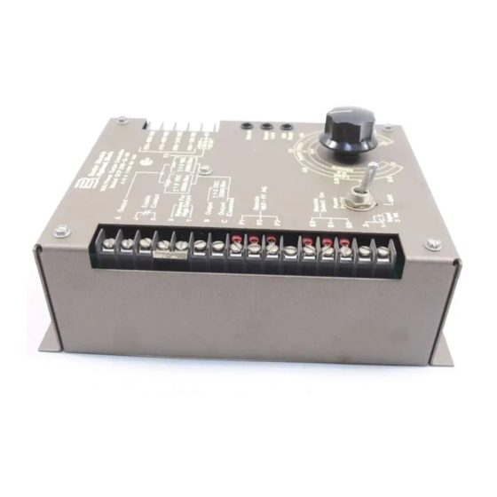
SECTION 2 • CONTROLS CONTROLS ILLUSTRATION AND DESCRIPTION SCP 250 controls are shown in Figure 2-1 and described in Table 2-1. Figure 2-1. SCP 250 Controls Table 2-1. Description of SCP 250 Controls Locator Control Description Mode Switch. This switch selects between var and power factor control. - Page 12 The control has two sets of calibration marks—one set for var control and one set for power factor control. The power factor calibration marks shown in Figure 2-1 are for an SCP 250-M and will differ from the power factor calibration marks on an SCP 250-G.
-
Page 13: Section 3 • Functional Description
Figure 3-1. SCP 250 Function Block Diagram INPUTS The SCP 250 has two inputs: a voltage input and a current input. The SCP 250 measures the real and reactive power based on these two inputs. The voltage input also supplies operating power to the SCP 250 power supply. -
Page 14: Voltage Limiting
When the external breaker is closed (52b contacts open), K1 de-energizes and enables the SCP 250 output. The SCP 250 control output is applied to the voltage regulator and the SCP 250 assumes a major portion of excitation control. -
Page 15: Section 4 • Installation
Highland, Illinois. MOUNTING The SCP 250 is intended for back-of-the-panel mounting in any plane. It should not be installed in a location where ambient operating temperature exceeds the range of –40 to 70°C (–40 to 158°F). SCP 250 dimensions are shown in Figure 4-1. All terminal screws are 6-32 on 0.375 inch (9.5 millimeter) centers. -
Page 16: Figure 4-1. Scp 250 Outline And Drilling Dimensions
Figure 4-1. SCP 250 Outline and Drilling Dimensions SCP 250 Installation 911000099Y Rev T... -
Page 17: Connections
CONNECTIONS SCP 250 connections will vary according to the application (generator or motor) and the type of voltage regulator used. The secondary voltage of the potential transformer used in an application determines which SCP 250 power connections are used. Input power (operating power and sensing voltage) is applied to terminal E1 and one of the following terminals: 120-139 Vac, 208-240 Vac, 416-480 Vac, or 520-600 Vac. -
Page 18: Figure 4-2. Avc63-12/Avc125-10 And Scp 250-G Connections
Figure 4-2. AVC63-12/AVC125-10 and SCP 250-G Connections SCP 250 Installation 911000099Y Rev T... -
Page 19: Figure 4-3. Kr-F/Kr-Ff And Scp 250-G Connections
Figure 4-3. KR-F/KR-FF and SCP 250-G Connections 911000099Y Rev T SCP 250 Installation... -
Page 20: Figure 4-4. Kr-F/Kr-Ff And Scp 250-M Connections
Figure 4-4. KR-F/KR-FF and SCP 250-M Connections SCP 250 Installation 911000099Y Rev T... -
Page 21: Figure 4-5. Mvc 236, Ra-70, And Scp 250-M Connections
Figure 4-5. MVC 236, RA-70, and SCP 250-M Connections 911000099Y Rev T SCP 250 Installation... -
Page 22: Figure 4-6. Sr-A And Scp 250-G Connections
Figure 4-6. SR-A and SCP 250-G Connections SCP 250 Installation 911000099Y Rev T... -
Page 23: Figure 4-7. Sr-A And Scp 250-M Connections
Figure 4-7. SR-A and SCP 250-M Connections 911000099Y Rev T SCP 250 Installation... -
Page 24: Figure 4-8. Sr-E/Sr-F/Sr-H And Scp 250-G Connections
Figure 4-8. SR-E/SR-F/SR-H and SCP 250-G Connections 4-10 SCP 250 Installation 911000099Y Rev T... -
Page 25: Figure 4-9. Sr-E/Sr-F/Sr-H And Scp 250-M Connections
Figure 4-9. SR-E/SR-F/SR-H and SCP 250-M Connections 911000099Y Rev T SCP 250 Installation 4-11... -
Page 26: Figure 4-10. Sse And Scp 250-G Connections
Figure 4-10. SSE and SCP 250-G Connections 4-12 SCP 250 Installation 911000099Y Rev T... -
Page 27: Figure 4-11. Sse And Scp 250-M Connections
Figure 4-11. SSE and SCP 250-M Connections 911000099Y Rev T SCP 250 Installation 4-13... -
Page 28: Figure 4-12. Ssr And Scp 250-G Connections
Figure 4-12. SSR and SCP 250-G Connections 4-14 SCP 250 Installation 911000099Y Rev T... -
Page 29: Figure 4-13. Xr2001/Xr2001F And Scp 250-G Connections
Figure 4-13. XR2001/XR2001F and SCP 250-G Connections 911000099Y Rev T SCP 250 Installation 4-15... -
Page 30: Figure 4-14. Xr2001/Xr2001F, Spm 2000, And Scp 250-G Connections
Figure 4-14. XR2001/XR2001F, SPM 2000, and SCP 250-G Connections 4-16 SCP 250 Installation 911000099Y Rev T... -
Page 31: Figure 4-15. Xr2002/Xr2002F And Scp 250-G Connections
Figure 4-15. XR2002/XR2002F and SCP 250-G Connections 911000099Y Rev T SCP 250 Installation 4-17... -
Page 32: Figure 4-16. Xr2003/Xr2003F And Scp 250-G Connections
Figure 4-16. XR2003/XR2003F and SCP 250-G Connections 4-18 SCP 250 Installation 911000099Y Rev T... -
Page 33: Remote Control Of The Scp 250
If user-supplied controls will be used, the controls installed on the SCP 250 chassis may be left in place. However, the controls must be disconnected from the SCP 250 by unsoldering and removing the control leads or taping the lead ends. - Page 34 This page intentionally left blank. 4-20 SCP 250 Installation 911000099Y Rev T...
-
Page 35: Section 5 • Operation
For example, in a 0.8 power factor load, reactive power is 75% of real power. This graph can be useful when adjusting the SCP 250 and evaluating system performance. This is particularly true when a varmeter and wattmeter are available but a power factor meter is not available. -
Page 36: Preliminary Adjustments For Power Factor Control
9. Set the Output Limit control for the variation that corresponds to about 5% more than the worst-case fluctuation of bus voltage. If the Output Limit control is set for too narrow a band, the SCP 250 may not provide control if bus voltage variation exceeds the percentage established by the Output Limit control. -
Page 37: Motor Applications
Adjust the Balance control until the system instrumentation indicates the desired power factor has been obtained. MOTOR APPLICATIONS The following procedures contain instructions for preliminary adjustment of the SCP 250 in motor applications. CAUTION Avoid establishing a lagging power factor so low as to cause the motor to pull out of synchronization. - Page 38 This page intentionally left blank. SCP 250Operation 911000099Y Rev T...
- Page 40 ROUTE 143, BOX 269 HIGHLAND, IL 62249 USA http://www.basler.com, info@basler.com PHONE +1 618-654-2341 FAX +1 618-654-2351...
Need help?
Do you have a question about the SCP 250 and is the answer not in the manual?
Questions and answers