
Related Manuals for Basler BE2000E


Summary of Contents for Basler BE2000E
- Page 1 INSTRUCTION MANUAL BE2000E Digital Voltage Regulator Publication: 9287500995 Revision: B Jan-15...
- Page 3 9287500995 Rev B Preface This instruction manual provides information about the installation and operation of the BE2000E Digital Voltage Regulator. To accomplish this, the following information is provided: • General information • Human-Machine Interface (HMI) • Functional description • Installation •...
- Page 4 The availability and design of all features and options are subject to modification without notice. Over time, improvements and revisions may be made to this publication. Before performing any of the following procedures, contact Basler Electric for the latest revision of this manual.
-
Page 5: Table Of Contents
Power Supply Inputs ..........................24 Chassis Ground ........................... 24 Power (Field) Output ..........................25 Relay Output ............................25 Communication Port ..........................25 BE2000E Connections for Typical Applications .................. 26 Preliminary Setup ............................ 31 Adjustments ............................. 31 Storage ..............................31 BESTCOMS™ Software ..........................33 Installation ............................... - Page 6 Changing Settings ........................... 36 Sending and Receiving Settings ......................36 Sending Settings ..........................36 Receiving Settings ..........................37 Saving Settings to BE2000E Memory....................37 Setting Definitions ............................ 37 System Configuration .......................... 37 System Settings ........................... 37 Setting Adjustments ..........................38 Control Gain ............................
- Page 7 9287500995 Rev B Metering ............................... 69 Environment ............................70 Type Tests ............................70 UL Approval ............................70 CSA Certification ..........................70 CE Compliance ............................ 70 Physical ..............................70 Revision History ............................71 BE2000E Contents...
- Page 8 9287500995 Rev B Contents BE2000E...
-
Page 9: General Information
The BE2000E is supplied in an encapsulated package designed for behind-the-panel mounting. The BE2000E is held in place by thread-forming screws that thread into its plastic shell. Front panel indicators (LEDs) annunciate regulator status and system conditions. BE2000E connections are made through quarter-inch, quick-connect terminals on the rear panel. - Page 10 9287500995 Rev B General Information BE2000E...
-
Page 11: Human-Machine Interface
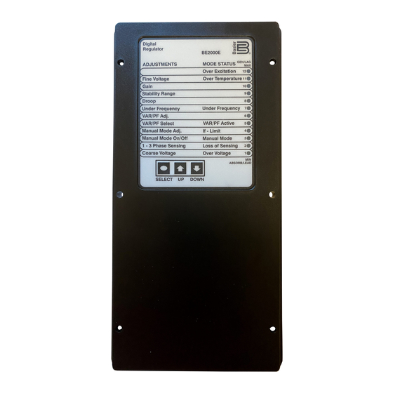
Front Panel Controls and Indicators BE2000E front panel controls and indicators consist of 12 red LEDs and three pushbuttons. Figure 1 illustrates the front panel controls and indicators of the BE2000E. The LEDs indicate control mode and status conditions and are also used when adjusting settings at the front panel. -
Page 12: Initial Adjustments
(80 V default) for 15 seconds. The BE2000E will shut down when an overexcitation condition is detected. The Over Excitation LED blinks for 5 seconds when the BE2000E is powered up following an overexcitation condition. -
Page 13: Making Settings Changes
0.1V. Successive presses of the “UP” or “DOWN” button shall continue to adjust the fine voltage setting. Pressing the “SELECT” button causes the regulator to exit the adjustment mode. Mode status LEDs blink approximately twice per second. Table 3. BE2000E Front Panel Adjustment Indicator Descriptions Indicator Description Fine Voltage This LED blinks slowly when the "Fine Voltage"... -
Page 14: Setting Level Indication
Coarse Voltage – LED #1 Blinking Slowly Maximum Adjustment Range Increment: 6 Vac Increase Decrease Minimum Maximum Minimum Maximum Value Value Value Value 600.00 Table 5. Sensing Mode (Single-phase/Three-phase) Select Single-phase/Three-phase select – LED #2 Blinking Slowly MODE Human-Machine Interface BE2000E... - Page 15 Manual Mode Adjust – LED #4 Blinking Slowly Adjustment Range: 0 to 3 Adc Increment: 0.01 Adc Minimum Value Maximum Value 2.75 2.50 2.74 2.25 2.49 2.00 2.24 1.75 1.99 1.50 1.74 1.25 1.49 1.00 1.24 0.75 0.99 0.50 0.74 0.25 0.49 0.24 BE2000E Human-Machine Interface...
- Page 16 Maximum Value * -100 * Minimum and maximum values may differ from the Table 9 values if the value has been changed in BESTCOMS™-BE2000E software. BESTCOMS-BE2000E has 0.5 percent resolution compared to the 1.0 percent resolution of the HMI. Human-Machine Interface...
- Page 17 -0.60 -0.66 † Minimum and maximum values may differ from the Table 10 values if the value has been changed in BESTCOMS-BE2000E software. BESTCOMS-BE2000E has 0.001 resolution compared to the 0.01 resolution of the HMI. Table 11. Underfrequency Adjustment Ranges Underfrequency Adjust –...
- Page 18 1.75 0.75 * Minimum and maximum values may differ from the Table 12 values if the value has been changed in BESTCOMS-BE2000E software. BESTCOMS-BE2000E has 0.01% resolution compared to the 0.25 percent resolution of the HMI. Table 13. Stability Range Selection Settings Stability Range Select –...
-
Page 19: Communication Port
Communication Port A communication port is located on the rear panel and consists of a female RS-232 (DB-9) connector. The communication port serves as an interface for programming (setup) of the BE2000E. Figure 2 illustrates the location of the communication port. - Page 20 9287500995 Rev B WARNING! LIVE TERMINALS AND HEATSINKS P 0007 - 41 Figure 2. Location of Communication Port Human-Machine Interface BE2000E...
-
Page 21: Functional Description
BE2000E functions are illustrated in the block diagram of Figure 3. A detailed description of each function block is provided in the paragraphs under the heading of BE2000E Function Blocks. BE2000E operating features include four operating modes, four protective functions, startup provisions, reactive droop compensation, underfrequency compensation, and an auxiliary analog input. -
Page 22: Contact Input Circuits
This input allows adjustment of the BE2000E regulation setpoint by the application of a positive or negative dc voltage across terminals A and B. Voltage up to +3 Vdc may be applied at this input. The circuit induces a 1,000-ohm burden on the dc source. -
Page 23: Communication Port
Closing a contact across terminals 52J and 52K disables var/power factor control. An open contact enables the BE2000E to control the generator reactive power in either the var or the power factor mode. For more information, refer to the Parallel Generator Compensation (52L/M) contact input. -
Page 24: Be2000E Operating Features
Var Control Mode In Var Control mode, the BE2000E maintains generator vars (volt-amperes, reactive) at a set level when paralleling with an infinite bus. The BE2000E calculates generator vars using the sensed generator output voltage and current quantities and then adjusts the dc excitation current to maintain vars at the setpoint. -
Page 25: Underfrequency
When generator frequency drops below the selected knee frequency setpoint, the voltage setpoint is automatically adjusted by the BE2000E so that generator voltage follows the selected PU (per unit) V/Hz curve. When operating on the selected PU V/Hz curve, the Underfrequency Active indicator flashes on the front panel and in BESTCOMS™-BE2000E software. -
Page 26: Generator Soft Start
Overexcitation Limiting (Field Current) The BE2000E has a field current limit that is factory preset at 6.5 amperes. The limit is adjustable from 0 to 7.5 amperes with an adjustable time delay that has a range of 0 to 10 seconds. Both settings are made through the Windows communication software. -
Page 27: Installation
9287500995 Rev B Installation The BE2000E is delivered in a sturdy carton to prevent shipping damage. Upon receipt, check the part number against the requisition and packaging list for agreement. Inspect for damage, and if there is evidence of such, immediately file a claim with the carrier and notify your sales representative or a sales representative at Basler Electric. - Page 28 9287500995 Rev B Figure 4. BE2000E Dimensions Installation BE2000E...
- Page 29 9287500995 Rev B Figure 5. Cutout and Drilling Dimensions BE2000E Installation...
-
Page 30: Connections
IBM compatible PCs and hand-held computers. Figure 6 shows the terminal connections located on the rear panel of the BE2000E. Except as noted above, connections should be made with minimum wire size of 14 AWG. - Page 31 9287500995 Rev B WARNING! LIVE TERMINALS AND HEATSINKS P 0007 - 41 Figure 6. BE2000E Rear Panel Terminals BE2000E Installation...
-
Page 32: Generator Voltage Sensing Inputs
This input allows adjustment of the BE2000E regulation setpoint by the application of a positive or negative dc voltage across terminals A and B. Voltage up to +3 Vdc may be applied at this input. The circuit induces a 1,000-ohm burden on the dc source. -
Page 33: Power (Field) Output
Table 17 identifies the RS-232 connector pin functions. A standard communication cable terminated with a DB-9 male connector is used for PC or hand-held computer interface with the BE2000E as shown in Figure 8. Figure 7. Communication Port Pin Assignments Table 17. -
Page 34: Be2000E Connections For Typical Applications
Figure 8. Personal Computer to BE2000E Connections BE2000E Connections for Typical Applications Figures 9 through 12 illustrate typical applications using the BE2000E. Figure 9 shows an application where the BE2000E is connected for three-phase voltage sensing. Figure 10 shows an application with single-phase voltage sensing while Figure 11 illustrates an application with a single-phase generator. - Page 35 9287500995 Rev B Figure 9. Typical Connections with ABC Rotation and Three-Phase Sensing BE2000E Installation...
- Page 36 9287500995 Rev B Figure 10. Typical Connections with ABC Rotation and Single-Phase Sensing Installation BE2000E...
- Page 37 9287500995 Rev B Figure 11. Typical Connections to a Single-Phase Generator BE2000E Installation...
- Page 38 9287500995 Rev B GEN 1 CTB1 CTB2 BE2000E LOAD ENABLE BE2000E CONTACT CTB1 CTB2 P0064-04 GEN 2 Figure 12. Cross-Current (Reactive Differential) Connections for Two Generators Figure 13. Cross-Current (Reactive Differential) Connections for Three or More Generators Installation BE2000E...
-
Page 39: Preliminary Setup
Dangerous voltage levels are present at the exposed heatsinks when the unit is energized. Tag and disconnect all wiring to the BE2000E. Be sure to insulate the wire terminals to prevent a short. Start the prime mover and perform all engine governor adjustments. - Page 40 9287500995 Rev B Installation BE2000E...
-
Page 41: Bestcoms™ Software
BESTCOMS-BE2000E provides a communication link between the BE2000E and the user. This software enables the user to enter all BE2000E settings and read all system metering values through an easy to use graphical interface. PID (Proportional + Integral + Derivative) software within the application enables the user to establish proper PID parameters based on a specified generator and/or exciter time constants. -
Page 42: Initial Adjustments
9287500995 Rev B Figure 14. BESTCOMS-BE2000E - Splash Screen Figure 15. System Configuration Screen Initial Adjustments Caution Read and understand the operation of the individual adjustments before attempting any initial adjustments. Before starting the generator, the procedures in the following paragraphs should be performed. -
Page 43: Establishing Communication
Open the BE2000E communication port by clicking on Communications on the menu bar, hovering the mouse pointer over Open Comm Port, and clicking RS-232 Port. Figure 16 illustrates the menu selections for opening the BE2000E communication port. -
Page 44: Changing Settings
Any setting changes made on a setting group screen must be sent to the BE2000E before viewing other screens. Otherwise, the setting changes will be lost. A single setting change can be sent to the BE2000E by pressing the Enter key on your PC keyboard. -
Page 45: Receiving Settings
Settings are saved in nonvolatile memory (EEPROM). In the event of a power loss, these are the settings that are active at power up. If settings are changed and sent to the BE2000E but not sent to EEPROM, the changed settings are lost if BE2000E operating power is lost. When exiting BESTCOMS-BE2000E or closing communication, you are asked if you want to save the settings to EEPROM. -
Page 46: Setting Adjustments
Generator CT Ratio. The ratio of the generator B-phase current transformer is entered in this setting field. This ratio allows the current displayed by the BE2000E to match the actual B-phase generator output current. A ratio of 1 to 1,000 may be entered in increments of 0.1. Note: A 500:5 CT has a ratio of 100. - Page 47 15 percent in 0.1 percent increments. Droop - Setpoint (%). This setting controls the reactive droop compensation feature of the BE2000E. The setpoint value is based on a 0.8 power factor load and determines the amount of change permitted in the generator voltage setpoint when the BE2000E responds to a reactive load.
- Page 48 This value defines the length of time that the Engine Unloading mode may be active before control is passed to the normal Underfrequency mode of operation. Droop time is adjustable from 1 to 5 seconds in 1 second increments. BESTCOMS™ Software BE2000E...
-
Page 49: Control Gain
Control gain settings are shown in Figure 24 and are described in the following paragraphs. Stability Range - This setting selects one of 7 preset stability ranges within the BE2000E. A guide for selecting the stability range is provided in Table 18. A setting of 21 enables the entry of custom stability settings through the BESTCOMS-BE2000E PID window. - Page 50 VAR/PF - PF Integral Gain KI. This setting adjusts the integral gain and determines the characteristic of the BE2000E dynamic response to a changed PF setting. PF KI values of 0 to 1,000 may be entered in increments of 0.01.
-
Page 51: Analysis
Figure 25 illustrates the settings, sensing values, and alarm signal indicators of the AVR tab. The settings of the AVR tab make it possible to increment and decrement the AVR setpoint of the BE2000E. The sensing values and alarm signal indicators of the AVR tab are also displayed by the other tabs of the Analysis screen. - Page 52 Figure 27 illustrates the settings, sensing values, and alarm signal indicators of the FCR tab. The settings of the FCR tab make it possible to increment and decrement the FCR setpoint of the BE2000E. The sensing values and alarm signal indicators of the FCR tab are also displayed by the other tabs of the Analysis screen.
- Page 53 If the FCR Analysis screen is left without returning to nominal setpoint a message box is shown (Figure 28) which allows the user to return to nominal setpoint by pressing YES or remain at the current setpoint by pressing NO. BE2000E BESTCOMS™ Software...
- Page 54 PF Setpoint field is selected by clicking the adjacent button. Clicking this button sends the PF Setpoint value to the BE2000E and changes the color of the button from gray to red. Power Factor Step Response - Increment of PF setpoint. This field indicates the increase that occurs to the PF setpoint when the corresponding increment button is clicked.
- Page 55 VAR Setpoint field is selected by clicking the adjacent button. Clicking this button sends the VAR Setpoint value to the BE2000E and changes the color of the button from gray to red. VAR Step Response - Increment of VAR setpoint. This field indicates the increase that occurs to the VAR setpoint when the corresponding increment button is clicked.
-
Page 56: Protection And Relay Settings
OEL - Current Level (A). The value of current in this field determines the excitation level that will cause the BE2000E to issue an overexcitation limit alarm. A current level of 0 to 7.5 A may be entered in 0.001 increments. -
Page 57: Metering, Operation And Alarms
Loss of Sensing Voltage - Time Delay (sec). The value of this field determines the time delay between when a loss of sensing voltage is recognized and the BE2000E responds according to the Hardware Shutdown and LOS Option options selected. A time delay of 0 to 25 seconds may be entered in 1 second increments. - Page 58 Figure 34. Metering, Operation and Alarms - Operation Tab Gen Frequency (Hz). This metering value indicates the frequency of the monitored generator voltage. Field Voltage (V). This metering value indicates the value of voltage being supplied from the BE2000E output (terminals F+ and F–) to the generator field.
- Page 59 External Adjust terminals (6D and 7 to decrease, 6U and 7 to increase) of the BE2000E. In AVR mode, each click of the Raise button increases the voltage setpoint 0.01 volts; each click of the Lower button decreases the voltage setpoint 0.01 volts.
-
Page 60: Pid Data
BESTCOMS-BE2000E enables generator stability to be set through the automatic calculation of PID parameters. PID stands for Proportional, Integral, Derivative. The word proportional means that the response of the BE2000E output is proportional or relative to the amount of change that is observed. BESTCOMS™ Software... -
Page 61: Pid Calculation Based On Input Values
9287500995 Rev B Integral means that the BE2000E output is proportional to the amount of time that a change is observed. Integral action eliminates offset. Derivative means that the BE2000E output is proportional to the required rate of excitation change. Derivative action avoids excitation overshoot. -
Page 62: Adding To The Pid List
BESTCOMS-BE2000E enables you to print a list of BE2000E settings, save BE2000E settings to a file, and open a settings file and upload those settings to a BE2000E. a settings file may also be opened and edited within any text editing software. -
Page 63: Saving Settings Files
Save. When the file command is given, a dialog box asks if you want to save the current settings into a BE2000E data file. Clicking Yes displays a Save As dialog box where the settings are assigned a file name and then saved. All BE2000E settings files are automatically given a *.BE2 extension by BESTCOMS-BE2000E. -
Page 64: Updating Embedded Firmware
Uploading Embedded Software. A warning window, Figure 40, will be displayed. The BE2000E should be disconnected from the generator and bus before continuing with this procedure and the current settings file should be backed up since uploading may replace some settings with defaults. - Page 65 Figure 41. Communication Settings Figure 42. Reading & Checking Settings Progress Bar The BE2000E Embedded Program Loader (Figure 43) will be displayed. Clicking the Get Device Information button displays the current device’s model number, style number, application program version, and serial number in the lower left hand corner of Figure 43.
- Page 66 Select the location of the embedded firmware update file, select the file, and click Open. The embedded firmware will begin transferring from the PC to the BE2000E. A progress bar, as displayed in Figure 46 marks the progress of the transfer.
-
Page 67: Terminating Communication
Close Comm Port. You are asked if you want to save the settings to EEPROM. This question is asked even if no changes were made to the BE2000E settings. When you execute the Close command (with a Yes or No to save settings to EEPROM), communication with the BE2000E is terminated. If you choose to exit BESTCOMS-BE2000E (by clicking File on the menu bar and then Exit) without first closing communication, you are still given the opportunity to save the settings to EEPROM. - Page 68 9287500995 Rev B BESTCOMS™ Software BE2000E...
-
Page 69: Maintenance And Troubleshooting
Basler Electric personnel. Troubleshooting If you do not get the results that you expect from the BE2000E, first check the programmable settings for the appropriate function. Use the following troubleshooting procedures when difficulties are encountered in the operation of your excitation system. -
Page 70: Low Generator Output Voltage
9287500995 Rev B Step 8. Replace the BE2000E unit. If replacing the BE2000E unit does not correct the malfunction, then the generator is defective. Consult with the generator manufacturer. Low Generator Output Voltage Step 1. Verify that the voltage adjustment is not set too low. -
Page 71: Poor Voltage Regulation
Step 1. Verify that the case of the BE2000E is properly grounded. If the BE2000E is not properly grounded, connect a dedicated ground wire to the quarter-inch fast-on connector labeled GND on the rear of the BE2000E case. If the BE2000E is properly grounded, proceed to Step 2. -
Page 72: Loss Of Generator Sensing Indicator Is Annunciating
If the generator is operating with a rated or less than rated load, proceed to Step 3. Step 3. Replace the BE2000E. If replacing the BE2000E does not correct the malfunction, proceed to Step 4. Step 4. Refer to the generator manual. Generator is defective. -
Page 73: No Droop
If the 52L/M contact input is open, proceed to Step 2. Step 2. Verify that the BE2000E 52J/K contact input is closed or the Var/PF function is disabled via the Windows® software. Var/PF operation must be disabled for droop operation. If Var/PF operation is disabled, proceed to Step 3. - Page 74 9287500995 Rev B Maintenance and Troubleshooting BE2000E...
-
Page 75: Specifications
9287500995 Rev B Specifications BE2000E electrical and physical specifications are listed in the following paragraphs. The adjustment increments shown apply to the PC software. Adjustment increments for the Front Panel Controls are listed in the Human-Machine Interface chapter. Operating Power Single-Phase ...... -
Page 76: Avr Operating Mode
Pickup ......... 0 to 250 Vdc Time Delay ......... 15 seconds (fixed) Field Overcurrent Protection Pickup Adjustment Range ...... 0 to 7.5 Adc Increment ........0.001 Adc Time Delay Adjustment Range ...... 0 to 10 seconds Increment ........1 second Specifications BE2000E... -
Page 77: Generator Overvoltage Protection
Accuracy........0.5% Power (Apparent, Real and Reactive) Range ......... 0 to 99 MVA, MW and Mvar Accuracy........3.0% Power Factor Range ......... –1.0 to –0.6, +0.6 to +1.0 Accuracy........0.02 Phase Angle Range ......... 0 to 360° Accuracy........2° BE2000E Specifications... -
Page 78: Environment
0.036” double amplitude (27 to 52 Hz) 5 G at 53 to 500 Hz Salt Fog .......... Tested per MIL-STD-810E UL Approval The BE2000E is recognized to applicable Canadian and US safety standards and requirements by UL. Standards used for evaluation: • UL6200 •... -
Page 79: Revision History
9287500995 Rev B Revision History BESTCOMS™ software changes are listed in Table 20. The corresponding revisions made to this instruction manual are summarized in Table 21. Revisions are listed in chronological order. Table 20. BESTCOMS Software Revision History Software Change Version and Date •... - Page 80 9287500995 Rev B Revision History BE1-11f...
- Page 82 12570 State Route 143 P.A.E. Les Pins No. 59 Heshun Road Loufeng District (N) 111 North Bridge Road Highland IL 62249-1074 USA 67319 Wasselonne Cedex Suzhou Industrial Park 15-06 Peninsula Plaza Tel: +1 618.654.2341 FRANCE 215122 Suzhou Singapore 179098 Fax: +1.618.654.2351...
Need help?
Do you have a question about the BE2000E and is the answer not in the manual?
Questions and answers