
Related Manuals for LifeFitness Club Seated Leg Curl Series


Summary of Contents for LifeFitness Club Seated Leg Curl Series
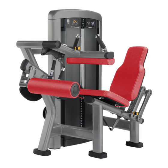
- Page 1 CLUB SERIES SEATED LEG CURL ASSEMBLY INSTRUCTIONS Part # 7138301 Revision: 10/12/01 Rev B...
-
Page 2: Table Of Contents
PARTS LIST PART # DESCRIPTION PART # DESCRIPTION 70435xx TOWER 3102922 3/8 X 2-3/4” BOLT 7041201 CABLE 3102904 3/8 X 3” BOLT 6692601 3 X 2 END CAP 3102942 3/8 X 3-1/2” BOLT 6714901 GUIDE ROD BUSHING 3102905 3/8 X 3-3/4” BOLT 3102903 3/8-16 X 2.5 BOLT 3102935... - Page 4 23 24 3/8 X 2-3/4” 14 3/8 X 3-3/4” 17 FIGURE 1 STEP 1: • LOOSELY assemble the top of the PIVOT ARM SUPPORT (2) to the TOWER (1) using four RH CAPS (30), two 3/8 X 2-3/4” BOLTS (14), four 3/8” SAE WASHERS (23), four 3/8” RH WASHERS (24) and two 3/8” LOW HEIGHT LOCK NUTS (21) as shown in FIGURE 1.
- Page 5 3/8 X 3-3/4” 17 FIGURE 2 STEP 2: • LOOSELY assemble the SEAT FRAME (9) to the PIVOT ARM SUPPORT (2) using four RH CAPS (30), two 3/8 X 3-3/4” BOLTS (17), four 3/8” SAE WASHERS (23), four 3/8” RH WASHERS (24), and two 3/8” LOW HEIGHT LOCK NUTS (21) as shown in FIGURE 2.
- Page 6 3/8 X 2-3/4” 14 17 3/8 X 3-3/4” FIGURE 3 STEP 3 • LOOSELY assemble the SEAT SUPPORT (8) to the SEAT FRAME (9) using four RH CAPS (30), two 3/8 X 3-3/4” BOLTS (17), four 3/8” SAE WASHERS (23), four 3/8” RH WASHERS (24) and two 3/8” LOW HEIGHT LOCK NUTS (21) as shown in FIGURE 3.
- Page 7 19 3/8 X 3” BUTTON HEAD FIGURE 4 STEP 4: • Slide one 2” ACCORDION SLEEVE (34), one 3” ACCORDIAN SLEEVE (35) and two PILLOW BLOCKS (27) over the shaft of the PIVOT ARM (4) as shown in FIGURE 4. •...
- Page 8 FIGURE 6 15 3/8 X 3” STEP 6: • SECURELY assemble the SEAT PAD (42) to the SEAT FRAME (9) using three RH CAPS (30), three 3/8 X 3” BOLTS (15) and three 3/8” RH WASHERS (24) as shown in FIGURE 6. 12 3/8 X 1-1/4”...
- Page 9 3/8 X 2-1/2” 13 3/8 X 3-1/2” 16 FIGURE 8 STEP 8: • SECURELY assemble the CAM SHROUD (6) to the PIVOT ARM SUPPORT (2) using four RH CAPS (30), four BLACK RH CAPS (46), two 3/8 X 3-1/2” BOLTS (16), two 3/8 X 2-1/2” BOLTS (13), eight 3/8” RH WASHERS (24) and four 3/8” LOW HEIGHT LOCK NUTS (21) as shown in FIGURE 8.
- Page 10 7039301=Adj. Plate 3203401=Bolt 3114502=Washer 3221501=Nut FIGURE 10 STEP 10: • Insert two 1/2” FLANGE BEARINGS (26) into the KNEE HOLD DOWN (3) as shown in FIGURE 10. FIGURE 11 1/2 X 3-1/4” 20 STEP 11: • Assemble the KNEE HOLD DOWN (3) to the KNEE HOLD DOWN SUPPORT (10) using one 1/2 X 3-1/4” SHOULDER BOLT (20), one 3/8”...
-
Page 11: Head Plate
FIGURE 12 HEAVY WEIGHT OPTION STEP 12: • Insert the two GUIDE RODS (38) (found in SHROUD KIT box) into the base of the TOWER (1) as shown in FIGURE 12. Lubricate the GUIDE RODS (38) with a slicon or teflon spray that is available at most hardware stores. •... -
Page 12: X 2-1/2" Bolt
FIGURE 13 13 3/8 X 2-1/2” TIGHTEN! STEP 13: • SECURELY assemble the GUIDE ROD SUPPORT (5) to the TOWER (1) using four RH CAPS (30), two 3/8 X 2-1/2” BOLTS (13), four 3/8” RH WASHERS (24) and two 3/8” LOW HEIGHT LOCK NUTS (21) as shown in FIGURE 13. (NOTE: Be sure to route cable through the hole of the GUIDE ROD SUPPORT (5) before tightening.) •... -
Page 13: X 4-1/2" Bolt
44 3/8 X 5” 3/8 X 4-1/2” 18 FIGURE 14 STEP 14: • Stabilize the PIVOT ARM (4) then SECURELY assemble the COUNTER BALANCE (7) to the PIVOT ARM (4) using two BLACK RH CAPS (46), one 3/8 X 4-1/2” BOLT (18), one 3/8 X 5” BOLT (44), three 3/8” SAE WASHERS (23), three 3/8” RH WASHERS (24) and one 3/8”... -
Page 14: Pillow Block
FIGURE 15 CABLE TIGHTEN! TIGHTEN! STEP 15: • Slide the end of the CABLE into the bushing on the PIVOT ARM (4) as shown in FIGURE 15. (NOTE: Make sure CABLE is properly aligned, then tighten set screws on PILLOW BLOCKS (27). •... - Page 15 FIGURE 16 STEP 16: • The WEIGHT STACK LABEL sheet (43) includes labels for both lbs. and kgs. for both the standard and optional weight stacks. • Peel the backing off the WEIGHT STACK LABELS (43), line up sheet to the right of the selector opening and apply labels to the WEIGHT PLATES (39 or 40), starting with the HEAD PLATE (11) as shown in FIGURE 16.
-
Page 16: Placard Label
FIGURE 17 STEP 17: • Assemble the PLACARD LABEL (36) or the FOREIGN LANGUAGE PLACARD LABEL (37) to the FRONT SHROUD as shown in FIGURE 17. -
Page 17: Guide Rod
• Upholstery with mild soap and water. • Guide rods with a cotton cloth. • Hand grips with mild soap and water. • Frame damage can be repaired with touch-up paint purchased from your LifeFitness customer service representative at (800)351- 3737. Inspect: •...
Need help?
Do you have a question about the Club Seated Leg Curl Series and is the answer not in the manual?
Questions and answers