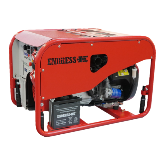
Endress ESE Series Original Operating Manual
Power generator
Hide thumbs
Also See for ESE Series:
- Translation of the operating instructions (452 pages) ,
- Use and maintenance manual (80 pages) ,
- Translation of the original operating manual (76 pages)
Table of Contents
Troubleshooting

Subscribe to Our Youtube Channel
Related Manuals for Endress ESE Series


Summary of Contents for Endress ESE Series
- Page 1 ESE Power Generator ORIGINAL OPERATING MANUAL ESE 1006 HG-GT ES Duplex Art-No. 113260 ESE 1006 DHG-GT ES Duplex Art-No. 113261 ESE 1306 DHG-GT ES Duplex Art-No. 113258 ESE 1506 DHG-GT ES Duplex Art-No. 113259 SEA 13 Art-No. 151747...
- Page 2 This documentation and parts thereof are subject to copyright. Any use or modi- fication beyond the restrictions of the Copyright Act is forbidden and subject to penalty without the consent of ENDRESS Elektrogerätebau GmbH. This applies in particular to copies, translations, microfilming, as well as storage and processing in electronic systems.
-
Page 3: Table Of Contents
Welcome to ENDRESS! ........ - Page 4 Starter battery ............52 9.3.1 Charging the battery .
-
Page 5: Directories
Directories Directories List of illustrations Fig. 3-1 Example of a type plate Fig. 3-2 Labels on the device Fig. 6-1 Views of the generator Fig. 6-2 Operating and exhaust-side components Fig. 6-3 Components on the engine and tank side Fig. 6-4 Control panel components full option Fig. -
Page 6: About This Manual
About this manual About this manual We would like to explain to you the safe and correct use of your generator in the best possible way through this operating manual. To do this we have oriented ourselves to the new European standard DIN EN 82079-1 for preparing the user manuals. - Page 7 About this manual the required distinctive warning notices at the correct point in time without impair- ing the legibility and comprehensibility of the operating manual. This is according to the regulations contained in the international standard DIN ISO 3864 de- scribes a fixed rule for all safety and warning notices, as shown in the following example.
- Page 8 About this manual Additional notices for operation or for function of a unit are marked with the adjacent symbol. NOTICE! The adjacent symbol is situated anywhere where the supplier documenta- tion must be read and observed and refers to, ► appropriate information, ►...
-
Page 9: Product Identification
Product identification Product identification Welcome to ENDRESS! We are pleased that you have made the decision to purchase a ENDRESS power generator. You have purchased a high-performance product into which we have embodied decades of our experience and have integrated many functions oriented on daily use. -
Page 10: Foreseeable Misuse
Product identification tion device. The power in the “On-site operation“ mode is taken through a spray water protected Schuko socket with a nominal voltage of 230V / 50 Hz 1~ or through a CEE 400V / 50 Hz 3~ socket, see Fig. 6-4 The generators must not be connected up directly to another energy distribution network (e.g. - Page 11 Product identification • The generator is never to be connected up to other energy distribution sys- tems (e.g. public power supply) or to other energy generation systems (e.g. other generators, solar plant, etc.). To start with this is usually not permitted by the energy supply company.
-
Page 12: Labels On The Generator
Product identification Labels on the generator An important part of the operating manual is in the form of labelling and notices on your generators. This The label must not be removed and must always be maintained in a legible condition. In a case of damage to the Labels can be or- dered from our customer service team. -
Page 13: Tab. 3-1 Meaning Of The Signs
Product identification Pos. Label Significance Note Tank capacity and fuel qual- Type plate Note Noise emissions Warning Dangers incurred during en- gine operation Potential equalisation (earthing for RCD) Warning signs Hot surfaces Risk of burns Note DGUV information Tab. 3-1 Meaning of the signs... -
Page 14: For Your Safety
For your safety For your safety The following chapter describes basic Safety instructions for safe operation of your generator. Your device is a very high-performance electrical machine which is potentially dangerous when operated if it has not been installed, commis- sioned, used, serviced and repaired according to the operating manual. - Page 15 For your safety Warning of corrosive substances This warning symbol indicates activities where a risk of chemical burns to the en- vironment as well as people exists, possibly with lethal consequences. Warning of environmentally damaging substances This warning symbol indicates activities where a risk of contaminating the envi- ronment exists, possibly with catastrophic consequences.
-
Page 16: General Safety Instructions
Residual risks As a manufacturer of EU-compliant machines, ENDRESS make great ef- forts to create designs which already eliminate possible risk potentials at the design stage. If this is not possible without significantly impairing the functions of a device, we implement suitable protective measures protect the user from injury. - Page 17 For your safety danger. Exactly impress upon yourself the identification marking of the four different danger levels in order to be able to reliably assess the dan- gers associated with the individual operating states and action steps when reading the operating manual. DANGER! DANGER describes a danger which represents a high level of risk,which can lead to death or severe injuries,when not avoided.
- Page 18 For your safety DANGER! Engine exhaust gases contain poisonous and partially invisible gases such as carbon monoxide (CO) and carbon dioxide (CO2). Risk of death due to poisoning or asphyxiation. ► Ensure that there is good ventilation during the whole period of operation. ►...
- Page 19 For your safety WARNING! Escaping corrosive acid fumes or sulphuric acid during and after the charging process. A risk of suffering severe or even deadly burns. ► Only work with acid-resistant protective equipment. ► Clean surfaces covered in acid immediately using adequate amounts of wa- ter.
- Page 20 For your safety NOTICE! Leaking engine oil and operating fluids can contaminate the soil and groundwater. ► Ensure that the generator is transported horizontally and mounted. ► Make all efforts, at all costs, to prevent escaping of operating fluids. ► Dispose of contaminated soil immediately and according to regulations. NOTICE! Use of wrong or outdated fuel damages or destroys the engine.
-
Page 21: Authorised Operating Personnel - Qualifications And Obligations
For your safety Authorised operating personnel – qualifications and obligations Your generators is a complex machine, the operation and maintenance of which requires exact knowledge of its functions and danger potentials. Therefore any work with or on the device, of any kind, may only be per- formed by authorised and instructed operating personnel. -
Page 22: Danger Zones And Work Areas
For your safety Danger zones and work areas In order to be able to consider all of a machine's safety aspects and to com- ply with the safety and health protection requirements of the applicable standards and EU directives, we have assessed the use of your generators in all of the phases that it will go through during its product service life (product life cycle). -
Page 23: Checking The Electrical Safety
Checking the electrical safety Checking the electrical safety Checking of electrical safety requires different measures to be taken which may only be undertaken by respectively authorised personnel. In doing so the respective, pertinent VDE provisions, EN and DIN standards, in their re- spectively valid versions, must be observed. -
Page 24: Tab. 5-1 Recommended Test Intervals
Checking the electrical safety NOTICE! The operating company is responsible for establishing and observing the periods between testing. Above all one must ensure observance of the re- spectively valid national regulations. We recommend the following checks and deadlines as general guideline values: When What / how First start-up at the op-... -
Page 25: Description Of The Device
Description of the device Description of the device Views The following section provides an overview of the designation and location of the most important components of your generator. It is important to make oneself familiar with these in order to further understand the de- scribed functions and operating steps and to be able to perform these safe- ly. -
Page 26: Operating And Exhaust-Side Components
Description of the device Operating and exhaust-side components Fig. 6-2 Operating and exhaust-side components Tank cover Control panel Fuse window Protective tank cover and fuse holder with compartment for operating manual Silencer and exhaust outlet Connection terminal Potential equalisa- tion / Earthing Starter battery 12 V Carrying handles (four) Alternator... -
Page 27: Components On The Engine And Tank Side
Description of the device Components on the engine and tank side Fig. 6-3 Components on the engine and tank side Oil dipstick Oil filling inlet Air filter housing Control panel Engine starter Air intake grille for engine cooling Engine hood Crane loading lug Exhaust grille Fuel tank... -
Page 28: Control Panel Components Full Option
Description of the device Control panel components full option Fig. 6-4 Control panel components full option Display Tank capacity Remote start socket (CPC) *** Insulation monitoring * Remote start socket fuse *** Multi-functional display Schuko attachment sockets 230V / 16A / CEE socket for 400V / 16A / 3~ CEE socket for 400V / 32A / 3~ Circuit breaker 32A... -
Page 29: Sea Control Panel Components
Description of the device SEA control panel components Fig. 6-5 SEA control panel components Display Tank capacity Remote start socket (CPC) *** Insulation monitoring Remote start socket fuse *** Multi-functional display Schuko sockets 230V / 16A / 1~ IP68 CEE socket for 400V / 16A / 3~ IP68 CEE socket for 400V / 32A / 3~ IP68 Circuit breaker 32A Circuit breaker 16A... -
Page 30: Commissioning
Commissioning Commissioning The following chapter describes the basic procedure for first time or re- peated putting into operation of the generator in "On-site operation" mode. Perform the following described steps when you put your generator into operation for the first time or put into operation again after transport. NOTICE! For start-up and operation of a generator on building and assembly sites, Deutsche Gesetzliche Unfallversicherung (DGUV) in DGUV Information... -
Page 31: Transport And Setup Of Your Generator
Commissioning • The same requirements apply to generators with an insulation monitoring de- vice (IMD). • Only rubber-insulated flexible cables of the type H07RN-F or H07BQ-F may be used on construction and assembly locations. • Electrical equipment must be spray water protected and meet the regulations for rough operation. -
Page 32: Fig. 7-1 Loading By Crane
Commissioning Carrying strap with sufficient load capacity is ready. DANGER! Danger of severe or mortal injuries being incurred from falling loads. ► Never stand under or close to a suspended load, also not to provide assis- tance. ► Ensure that there is no person in the area of swivel of the lifting device. ►... -
Page 33: Refuelling Your Generator
Commissioning Refuelling your generator Proceed as follows to the generator. Requirements The generator must be turned off The generator is cooled down There must be an adequate air supply and air removal All power consuming equipment must be disconnected or switched off DANGER! Leaking engine oil and fuel can burn or explode. -
Page 34: Starting The Generator
Commissioning Starting the generator This section describes how to start the generators for manual use, i.e. with consumers that are connected to the generators power sockets. The cold start device is designed to be either a hand choke or automatic choke, depending on the selected option. -
Page 35: Fig. 7-2 Engine Start On Control Panel
Commissioning Starting the motor Fig. 7-2 Engine start on control panel Manual choke 1. Pull the choke lever out to the stop. 2. Turn the engine start switch to the right stop in the "START" position. The engine starts. 3. Release the engine start switch and it will spring back into the "ON" position. 4. -
Page 36: Turning Off Your Power Generator
Commissioning NOTICE! Do not apply load to the generator immediately after a cold start. ► Allow the generator engine to warm up for a few minutes before switching on a load when the generator has not been operating for more than eight hours (or for very low external temperatures). -
Page 37: Turn Off Your Generator In The Event Of An Emergency
Commissioning Turn off your generator in the event of an EMER- GENCY Your generators is fitted with an EMERGENCY-STOP smash button, (this depends on the version) . It enables you to immediately switch the de- vice off in an EMERGENCY. CAUTION! The EMERGENCY-STOP smash button is only to be used in the event of a dangerous situation arising in an emergency. -
Page 38: Connection Of Power Consuming Equipment
Commissioning Connection of power consuming equipment DANGER! Mortal danger due to an electric shock if live parts are touched. ► Never operate generators if it is in a damaged condition. ► Never operate the electrical consumers and connecting cable (power con- suming equipment) in a damaged condition. - Page 39 Commissioning IMPORTANT INFORMATION REGARDING THE CONNECTING UP OF CONSUMERS Your generator is designed for mobile use and according to the protective mea- sure Protective separation with potential equalisation designed according to DIN VDE 0100-551:2017-02 (HD 60364-5-551 + A11:2016-05) DANGER! Risk of dangerous contact voltages occurring when several consumers are used from a single generator.
- Page 40 Commissioning CAUTION! Danger due to malfunctioning of the protective measures against hazard- ous shock voltages with an extended supply network! ► Keep the length of the connecting line as short as possible. ► Use as few sub-distributions as possible. ► Take note of the table below. Line max.
-
Page 41: The Device In-Use
The device in-use The device in-use Using the ECD 02 control display The control displays allow one to display the various operating states of the generator. The display starts automatically as soon as the generator has started. Fig. 8-1 Control Display ECD 02 1. -
Page 42: Optional Fittings
The device in-use Optional fittings The following chapter describes the function and operation of optional equipment features that you either ordered from the factory or purchased later on as accessories. Use your order documents to check which options were fitted to your generators. 8.2.1 ECOtronic (idle down) Proceed as follows to operate the generator with idling speed reduction. -
Page 43: Fig. 8-2 Fi Circuit Breaker (Rcd)
The device in-use It is essential to observe the regulations and safety instructions of the DGUV in- formation 203-032 mentioned in order to achieve body protection for all persons working in the connected distributor network. We strongly recommend that you also comply with the requirements of DGUV In- formation 203-032 for other purposes. -
Page 44: Insulation Monitoring, With Switching Off
The device in-use Symbol Significance POS 0 Protection switch triggers. FI circuit breaker is working correctly. The device has been tested in compliance with DIN VDE 0100-551. 1. Circuit breaker Fig. 8-2 - Move the circuit breaker back into POS I in order to be able to operate consumers from the generator again. - Page 45 The device in-use Lamp Result Significance lights up red Line circuit breaker jumps to Insulation monitoring POS 0 is OK stays off Line circuit breaker remains Insulation monitoring in POS 1 is defective stays off Line circuit breaker jumps to Lamp defective POS 0 The insulation monitoring function has been successfully tested.
-
Page 46: Remote Start Device
The device in-use WARNING! Risk of touching surfaces that are live due to faulty insulation. Danger of electric shock if a second insulation fault occurs. ► The relevant consumable is not to be used any more after an insulation fault has been determined. - Page 47 The device in-use Start the engine us- Proceed as follows to start the generator from the control panel on the ca- ing remote start ble remote control after connecting up as described above: 1. Turn the switch into the "ON" position. 2.
-
Page 48: Using An Exhaust Hose
The device in-use 8.2.5 Using an exhaust hose If you have purchased your generator with the optional exhaust hose, the silencer has a connection that enables you to channel the engine exhaust gases away from the generator's immediate vicinity. DANGER! Engine exhaust gases contain poisonous and partially invisible gases such as carbon monoxide (CO) and carbon dioxide (CO2). - Page 49 The device in-use Proceed as follows to disconnect the exhaust hose from the generator: Requirements The generator must be turned off The exhaust hose has cooled down sufficiently. CAUTION! Certain surfaces on the generators can get very hot whilst running. Risk of burns ►...
-
Page 50: Maintenance
Maintenance Maintenance generators maintenance is described in this section. It may only be per- formed by qualified specialist personnel. Maintenance and repair which is neither described in this operating manual nor in the possibly also delivered operating and maintenance instructions may only be undertaken by authorized service personnel from the manu- facturer. -
Page 51: Maintenance Work
Maintenance Maintenance work Maintenance interval according to time or operating hours [h] Item Every First Every 6 Every Every 2 8h /daily month / months year / years / Page / 100h 300h 500h Spark plug Test, ad- just Change Spark protection Cleaning Idle down... -
Page 52: Starter Battery
Maintenance CAUTION! Certain surfaces on the generators can get very hot whilst running. Risk of burns ► Never touch any engine parts (in particular the exhaust system) for a few min- utes after ceasing operation. ► Always leave hot engine parts to cool down before touching them. NOTICE! Also always read about the checking and maintenance work which con- cerns the electrical safety of the generators in the chapter “Checking the... -
Page 53: Replacing The Battery
Maintenance If the generator cannot be started after fully charging the battery, there is a defect in the starter power circuit of the generator. Contact your service partner. NOTICE! The starter battery from the factory is maintenance-free throughout its en- tire service life. -
Page 54: Engine Oil
Maintenance Fig. 9-1 Replacing the starter battery 1. Make ready a new starter battery (Observe the instructions from the battery manufacturer. 2. Place the starter battery in the battery compartment. 3. Attach the red cable to the battery's positive terminal FIRST and then pull the red protective cap over the terminal. -
Page 55: Checking The Oil Level
Maintenance Fig. 9-2 Viscosity grade of engine oil (source: HONDA) 9.4.1 Checking the oil level Your generator is fitted with an oil lack automatic switching off system to avoid engine damage occurring due to a low engine level. It has two functions: 1) it prevents the engine from starting for an inadequate engine oil level 2) it switches off the drive motor when the engine oil level falls below the mini- mum value while operating. -
Page 56: Changing The Engine Oil
Maintenance Fig. 9-3 Oil dipstick and oil drainage plug Oil drain screw Oil filling inlet Oil dipstick 9.4.2 Changing the engine oil The engine oil is subject to ageing and it must be changed periodically, depend- ing on the operating conditions, in order to be able to fulfil its lubricating, cleaning and internal engine cooling tasks. -
Page 57: 10 Storage
Storage 10 Storage It is important to store the device at a suitable storage location as soon as your generator is no longer being used. • The storage location must be roofed and must not be subjected to standing water, aggressive vapours or soiling as well as major accumulation of dust. •... -
Page 58: 11 Disposal
Pure b2b devices (devices which, for appropriate use, or exclusively are only used the commercial area) must not be disposed of over public collecting points in Germany and further EU countries. Speak to your authorised ENDRESS gen- erator dealer about handing back your recycling waste electrical equipment. The dealer is also your point of contact for any differing regulations on the respective country of deployment. -
Page 59: 12 Troubleshooting
Troubleshooting 12 Troubleshooting The following table is an aid for you to use in a case where faults arise during use. Based on experience a number of malfunctions can already be removed by operating personnel or the possible causes limited. In all other cases contact your service partner as described in the table. - Page 60 Troubleshooting Malfunction possible cause Correction Fuel level too low Top up with fuel The fuel filter is clogged. Replace the fuel filter. Engine oil level too low (oil lack auto- Bring the engine oil level up to The engine starts but stops matic switch-off) the maximum again shortly afterwards...
-
Page 61: Tab. 12-1 Troubleshooting
Please contact our customer service for further fault diagnosis as well as pro- curement of original spare parts and wear parts at Customer service: Tel. +49-(0)-7123-9737-44 Email: service@endress-generator.de www.endressparts.com (see Chapter 14 Have the item and serial number of your device ready for identification. You will... -
Page 62: 13 Technical Data
Technical data 13 Technical data The following table contains the technical data for your generator. Name Value Unit ESE 1006 ESE 1006 ESE 1306 ESE 1506 HG-GT DHG-GT DHG-GT DHG-GT ES Duplex ES Duplex ES Duplex ES Duplex Maximum power output [LTP] ~3 / [kVA] Continuous power output [PRP] ~3 [kVA]... - Page 63 Technical data The information given in the table applies to the following operating conditions (standard reference conditions): standard reference conditions Name Value Unit Setting up height above sea level Ambient temperature [°C] Relative air humidity The usable power output can deviate from the nominal values depending on the actual operating conditions.
-
Page 64: 14 Replacement Parts
Replacement parts 14 Replacement parts Maintenance and replacement parts can be obtained quickly and easily from your responsible ENDRESS service partner or ENDRESS dealer. You can alternatively obtain support from our central customer service by telephone: +49 (0) 71239737-44 by email: service@endress-stromerzeuger.de Have the item and serial number of your device ready for identification. - Page 65 Replacement parts NOTES...
-
Page 66: Keyword Index
Replacement parts Keyword index Air filter housing 27 Maintenance page 25 Air intake grille 27 Maximum line length 40 Maximum power output 62 misuses 10 Carrying handle 26 27 Multi-functional display 28 29 carrying handles 31 Circuit breaker 28 29 Control panel 26 Noise emissions 13 Engine starter 27... - Page 67 Replacement parts Warning notices 16 WEEE directive 58 Weight 62...
- Page 68 Elektrogerätebau GmbH Neckartenzlinger Str. 39 D-72658 Bempflingen, Germany Tel: +49 (0) 7123 /9737-0 Fax: +49 (0) 7123 /9737-50 Email: info@endress-stromerzeuger.de www: www.endress-stromerzeuger.de © 2018, ENDRESS Elektrogerätebau GmbH...
Need help?
Do you have a question about the ESE Series and is the answer not in the manual?
Questions and answers