Sign In
Upload
Download
Table of Contents
Contents
Add to my manuals
Delete from my manuals
Share
URL of this page:
HTML Link:
Bookmark this page
Add
Manual will be automatically added to "My Manuals"
Print this page
×
Bookmark added
×
Added to my manuals
Manuals
Brands
Endress Manuals
Inverter
Ecopower Series
Operating instructions manual
Endress Ecopower Series Operating Instructions Manual
Power generators
Hide thumbs
1
2
Table Of Contents
3
4
5
6
7
8
9
10
11
12
13
14
15
16
17
18
19
20
21
22
23
24
25
26
27
28
29
30
31
32
33
34
35
36
37
38
39
40
41
42
43
44
45
46
page
of
46
Go
/
46
Contents
Table of Contents
Troubleshooting
Bookmarks
Table of Contents
Table of Contents
1 About These Instructions
Signs and Symbols Used
General Signs / Symbols
Safety Symbols
2 General Safety Guidelines
Intended Use
Foreseeable Misuse and Incorrect Operation
Residual Risks
Qualifications and Duties
Personal Safety Equipment
Hazard Areas and Work Places
Labelling on the Power Generator
General Safety Instructions
3 Description
Function and Mode of Operation
4 Putting the Power Generator into Operation
Dismantle the Transport Safety Device
Transporting the Power Generator
Setting-Up the Power Generator
Fuelling the Power Generator
Filling the Power Generator with Motor Oil
Starting the Power Generator
Switching off the Power Generator
Shutting down Power Generator (Longer Term Shut Down)
5 Servicing the Power Generator
Service Plan
Servicing Work
Checking Electrical Safety
6 Trouble Shooting
7 Technical Data
8 Terms of Warranty
Advertisement
Quick Links
1
Function and Mode of Operation
2
Fuelling the Power Generator
3
Filling the Power Generator with Motor Oil
4
Trouble Shooting
5
Technical Data
Download this manual
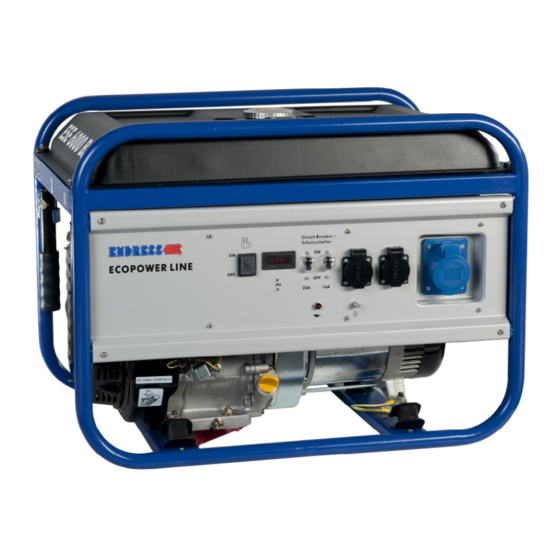
Power Generators
OPERATING
INSTRUCTIONS
ESE 3000 BS
240 209
ESE 6000 BS
240 210
ESE 6000 DBS
240 211
Table of
Contents
Previous
Page
Next
Page
1
2
3
4
5
Advertisement
Table of Contents
Need help?
Do you have a question about the Ecopower Series and is the answer not in the manual?
Ask a question
Questions and answers
Related Manuals for Endress Ecopower Series
Portable Generator Endress ECO Power Line ESE 3000 BS Translation Of The Original Operating Manual
(60 pages)
Inverter Endress ESE Series Use And Maintenance Manual
(80 pages)
Inverter Endress ESE Series Original Operating Manual
Power generator (68 pages)
Inverter Endress ESE Series Translation Of The Original Operating Manual
Power generator (64 pages)
Inverter Endress ESE 406 HG-GT ES DUPLEX Operating Instructions Manual
(79 pages)
Inverter Endress ESE 506 HG-GT DUPLEX Operating Instructions Manual
(79 pages)
Inverter Endress ESE 6000 DBS Operating Instructions Manual
Power generators (46 pages)
Inverter Endress ESE 604 DHG DIN Translation Of The Original Operating Instructions
(92 pages)
Inverter Endress ESE 607 DBG DIN Operating Manual
(79 pages)
Inverter Endress ESE 608 DHG ES DI DUPLEX Operating Instructions Manual
(56 pages)
Inverter Endress ESE 2000I Operating Manual
(40 pages)
Inverter Endress ESE Original Operating Manual
Power generator (58 pages)
Inverter Endress ESE 30YW/RS Original Operating Manual
(52 pages)
This manual is also suitable for:
Ese 3000 bs
Ese 6000 bs
Ese 6000 dbs
Table of Contents
Print
Rename the bookmark
Delete bookmark?
Delete from my manuals?
Login
Sign In
OR
Sign in with Facebook
Sign in with Google
Upload manual
Upload from disk
Upload from URL


Need help?
Do you have a question about the Ecopower Series and is the answer not in the manual?
Questions and answers