Endress ESE Series Translation Of The Original Operating Manual
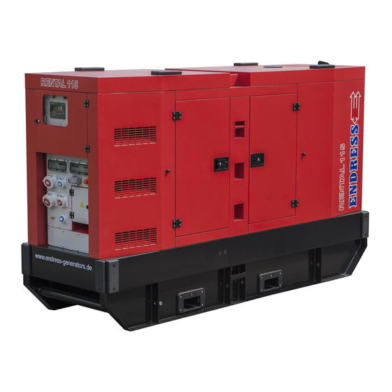
Power generator
Hide thumbs
Also See for ESE Series:
- Translation of the operating instructions (452 pages) ,
- Use and maintenance manual (80 pages) ,
- Translation of the original operating manual (76 pages)

Related Manuals for Endress ESE Series


Summary of Contents for Endress ESE Series
- Page 1 ESE Power Generator TRANSLATION OF THE ORIGINAL OPER- ATING MANUAL ESE 75-250 IW/AS Article-No.: 339280 - 339287...
- Page 2 This documentation and parts thereof are subject to copyright. Any use or modi- fication beyond the restrictions of the Copyright Act is forbidden and subject to penalty without the consent of ENDRESS Elektrogerätebau GmbH. This applies in particular to copies, translations, microfilming, as well as storage and processing in electronic systems.
-
Page 3: Table Of Contents
Welcome to ENDRESS! ........ - Page 4 8.4.2 Changing the engine oil..........52 Storage .
-
Page 5: Directories
Directories Directories List of illustrations Fig. 3-1 Example of a type plate Fig. 3-2 included in delivery Fig. 3-3 Labels on the device Fig. 6-1 Views of the generator Fig. 6-2 Components on the exhaust and operating side Fig. 6-3 Components on the exhaust and maintenance side Fig. -
Page 6: About This Manual
About this manual About this manual We would like to explain to you the safe and correct use of your generator in the best possible way through this operating manual. To do this we have oriented ourselves to the new European standard DIN EN 82079-1 for preparing the user manuals. -
Page 7: Using This Operating Manual
About this manual Using this operating manual In order to increase the legibility, comprehensibility and transparency of the document, certain information is highlighted or identified according a uniform system. The following particularly belong in this category: signs warning about dangers to life and limb Safety and warning notices are necessary at all locations where there is potential danger from the device which cannot be eliminated by design or operational measures. - Page 8 About this manual Symbols and formattings in the text In order to increase the legibility, comprehensibility and transparency of the doc- ument, various information and activities are awarded uniformly repeating bullets or formattings. The following example shows presentation of a sequence of ac- tions with established work steps: Example: ...
-
Page 9: Product Identification
Product identification Product identification Welcome to ENDRESS! We are pleased that you have made the decision to purchase a ENDRESS power generator. You have purchased a high-performance product into which we have embodied decades of our experience and have integrated many functions oriented on daily use. -
Page 10: Foreseeable Misuse
Product identification to DIN VDE 0100-551: 2017-02 is used as the protective separation measure. The protective conductor system from the attached consumers will take over the earthing function. The terminal strip (Fig. 6-4 ) is used for connecting up a suit- able earth (e.g. - Page 11 Product identification • Never refuel the generator’s own tank when it is hot. Overflowing fuel and outflowing fuel vapours can ignite on hot parts of the device. • The generator is never to be connected up to other energy distribution sys- tems (e.g.
-
Page 12: Included In Delivery
Product identification included in delivery Apart from the technical documentation mentioned in Chapter 2.1 the following articles are Scope of delivery of your generator: Fig. 3-2 included in delivery Item Name Supplier documentation Tool kit Coolant overflow tank (no image operating manual shown) -
Page 13: Labels On The Generator
Product identification Labels on the generator An important part of the operating manual is in the form of labelling and notices on your generator. These labels must not be removed and they must always be maintained in a legible condition. New labels can be ordered from our customer service team if the originals become damaged. - Page 14 Product identification Item Label Significance Warning Mortal danger from toxic combustion gases when the engine is running Risk of burns Hot surfaces Note Lift the unit only from here (crane loading eyes) Prohibition signs Smoking and open flames are prohibited Note Fuel quality Read the operating manual...
- Page 15 Product identification Item Label Significance Warning signs Dangerous voltage For electricians only Type plate Prohibition signs No naked flames Tab. 3-1 Labels on the device...
-
Page 16: For Your Safety
For your safety For your safety The following chapter describes basic Safety instructions for safe operation of your generator. Your device is a very high-performance electrical machine which is potentially dangerous when operated if it has not been installed, commis- sioned, used, serviced and repaired according to the operating manual. - Page 17 For your safety Warning of corrosive substances This warning symbol indicates activities where a risk of chemical burns to the en- vironment as well as people exists, possibly with lethal consequences. Warning of environmentally damaging substances This warning symbol indicates activities where a risk of contaminating the envi- ronment exists, possibly with catastrophic consequences.
-
Page 18: General Safety Instructions
Residual risks As a manufacturer of EU-compliant machines, ENDRESS make great ef- forts to create designs which already eliminate possible risk potentials at the design stage. If this is not possible without significantly impairing the functions of a device, we implement suitable protective measures protect the user from injury. - Page 19 For your safety danger. Exactly impress upon yourself the identification marking of the four different danger levels in order to be able to reliably assess the dan- gers associated with the individual operating states and action steps when reading the operating manual. DANGER! DANGER describes a danger which represents a high level of risk,which can lead to death or severe injuries,when not avoided.
- Page 20 For your safety DANGER! Mortal danger due to an electric shock if live parts are touched. ► Never operate the device if it is in a damaged condition. ► Never operate the electrical consumers and connecting cable (power con- suming equipment) in a damaged condition. ►...
- Page 21 For your safety WARNING! There is a risk of explosion and fire in the case of inappropriate handling and spark development when working with the battery. Danger from spraying sulphuric acid. Danger of suffering severe even deadly burns and chemical burns. Danger of being blinded. ►...
- Page 22 For your safety NOTICE! Leaking engine oil and operating fluids can contaminate the soil and groundwater. ► Ensure that the generator is transported horizontally and mounted. ► Make all efforts, at all costs, to prevent escaping of operating fluids. ► Dispose of contaminated soil immediately and according to regulations. NOTICE! Use of wrong or outdated fuel damages or destroys the engine.
-
Page 23: Authorised Operating Personnel - Qualifications And Obligations
For your safety Authorised operating personnel – qualifications and obligations Your Generators is a complex machine, the operation and maintenance of which requires exact knowledge of its functions and danger potentials. Therefore any work with or on the device, of any kind, may only be per- formed by authorised and instructed operating personnel. -
Page 24: Danger Zones And Work Areas
For your safety Danger zones and work areas In order to be able to consider all of a machine's safety aspects and to com- ply with the safety and health protection requirements of the applicable standards and EU directives, we have assessed the use of your Generators in all of the phases that it will go through during its product service life (product life cycle). -
Page 25: Checking The Electrical Safety
Checking the electrical safety Checking the electrical safety Checking of electrical safety requires different measures to be taken which may only be undertaken by respectively authorised personnel. The respec- tive valid versions of the appropriate and relevant standards must be ad- hered to. - Page 26 Checking the electrical safety When What / how First start-up at the op- • See Chapter 7 and also abide by the operating manual Operating erating location provided by the engine manufacturer personnel • Visual inspection for externally visible defects such as transport damage.
-
Page 27: Description Of The Device
Description of the device Description of the device Power generator view The following section provides an overview of the name and location of the most important components in your Generatorss. It is important that you become familiar with them in order to understand the functions and oper- ating steps explained below and to be able to implement them safely. -
Page 28: Components On The Connecting Side
Description of the device Components on the connecting side Fig. 6-2 Components on the exhaust and operating side Generator’s maintenance flap Crane loading lug Control panel Engine’s maintenance access point Oil drain pump Oil filter Fuel tank’s filling opening Forklift pockets... -
Page 29: Components On The Maintenance Side
Description of the device Components on the maintenance side Fig. 6-3 Components on the exhaust and maintenance side Engine’s maintenance doors Fuel filter Oil filling cap Oil dipstick Air filter... -
Page 30: Control Panel Components
Description of the device Control panel components Fig. 6-4 Components on the control panel EMERGENCY-STOP smash button Control module E-MCS 6.0 Main switch Control module’s ON / OFF switch Terminal strip cover (only to be ac- Terminal strip cessed by electricians!) -
Page 31: Commissioning
Commissioning Commissioning The following chapter explains the basic procedure for initial or repeated generator start-ups in "Manual" mode. Follow the working steps described below when you put your generator into operation for the first time or re- start it again after transporting it. Transporting and preparing your generator Choose the transporting vehicle and lifting gear so that the generator can be moved safely at all times according to its total mass (see Chapter 12 ). - Page 32 Commissioning Fig. 7-1 Transporting with a forklift Transporting with a 1. Move the lifting forks into the pockets in the base frame. lifting device 2. Insert the lifting forks as far as possible because of the machine’s heavy weight. 3. Raise the power generator slowly and evenly. 4.
-
Page 33: Refuelling Your Generator
Commissioning Fig. 7-2 Top Transporting by 1. Connect up to the crane eyes to the lifting device approved for use with crane the unit’s heavy weight and secure it against falling off. 2. Raise the power generator slowly and evenly. 3. - Page 34 Commissioning NOTICE! Leaking fuel can contaminate soil and groundwater. ► Take note of the residual quantity in the tank and its maximum filling capacity. ► Always bear in mind that the fuel gauge reacts only after a time delay. ► Fill the tank to a maximum of 95%. ►...
-
Page 35: Starting The Generator
Commissioning Starting the generator Starting the power generator in manual control mode (see Chapter 7.4 ) is described here. Proceed as follows to start the power generator directly from the E-MCS 5.0 con- trol module’s control panel. Fig. 7-3 Manually starting and stopping the power generator Requirements: ... - Page 36 Commissioning DANGER! Leaking engine oil and fuel can burn or explode. A risk of suffering severe even deadly burns. ► Prevent engine oil or fuel from leaking out. ► Remove leaked operating fluids immediately and appropriately. ► Never use an additional start aid. ►...
-
Page 37: Operating The E-Mcs 6.0 Control Module
Commissioning Operating the E-MCS 6.0 control module We will explain in detail how to operate the power generator via the control module in the following chapter, (see Fig. 6-4 ), and under various operating conditions. You will also learn how to display and edit various operating parameters and error messages. - Page 38 Commissioning NOTICE! Automatic mains switching is deactivated in the “ “ control mode. The power generator will not start if the power supply has failed. ► Only use the manual control mode for temporary purposes or if automatic mains switching is not needed. ►...
-
Page 39: Descriptions Of The Operating And Display Buttons
Commissioning 7.4.1 Descriptions of the operating and display buttons Fig. 7-5 Control module’s control panel Item Button Description START ENGINE Press this button to start the power generator if the control mode has been selected, see SWITCH OFF ENGINE as well Press this button oncein control mode and the control module will start the power generator’s cooling- down phase and it will be switched off afterwards. - Page 40 Commissioning Item Button Description CHANGE GENERATOR MODE (only with an external changeover contactor). Press this button to go to the control mode for supplying the con- nected distribution network from the power generator. CHANGING THE MAINS OPERATION (only with an external change- over contactor) Press this button to enter the control mode for supplying the con-...
-
Page 41: Display Window On The Control Module's Screen
Commissioning Item Description GENERATOR FAULT The red LED will flash if the power supply from the power generator is faulty. It will go out if the button is pressed after the problem has been eliminated. The fault is still present if it remains permanently lit. Tab. -
Page 42: Low Load Diesel Engine Operation
Commissioning Low load diesel engine operation Internal combustion engines normally run most economically and environmental- ly friendly when they have reached their optimum operating temperature (with a coolant temperature from approx. 80°C). Prolonged operation well below the op- erating temperature or without a specific minimum load will have a negative effect on the service life. -
Page 43: Turn Off Your Generator In The Event Of An Emergency
Commissioning Turn off your generator in the event of an EMER- GENCY Your Generators is fitted with an EMERGENCY-STOP smash button . It enables you to immediately switch off the device in an EMERGENCY in or- der to prevent other dangerous situations from occurring. CAUTION! The EMERGENCY-STOP smash button is only to be used in the event of a dangerous situation arising in an emergency. -
Page 44: Connection Of Power Consuming Equipment
Commissioning Connection of power consuming equipment DANGER! Mortal danger due to an electric shock if live parts are touched. ► Never operate the device if it is in a damaged condition. ► Never operate the electrical consumers and connecting cable (power con- suming equipment) in a damaged condition. -
Page 45: Maintenance
Maintenance Maintenance Generators maintenance is described in this section. It may only be per- formed by qualified specialist personnel. Maintenance and repair which is neither described in this operating manual nor in the possibly also delivered operating and maintenance instructions may only be undertaken by authorized service personnel from the manu- facturer. -
Page 46: Maintenance Work
Maintenance daily / after 8 hours (during operating times) Check the engine oil level Check the coolant level Check the cleanliness of the heat exchanger Check the cleanliness of the air filter Drain off the water from the fuel pre-filter ... -
Page 47: Starter Battery
Maintenance CAUTION! Certain surfaces on the device can get very hot whilst it is running. Risk of burns ► Never touch any engine parts (in particular the exhaust system) for a few min- utes after ceasing operation. ► Always leave hot engine parts to cool down before touching them. NOTICE! Also always read about the checking and maintenance work which con- cerns the electrical safety of the generators in the chapter “Checking the... -
Page 48: Replacing The Battery
Maintenance 1. Attach the starter battery according to the regulations from the battery and charger manufacturers. 2. Set a suitable charge current for the charger if necessary. 3. Switch off the charger of expiry of the charging time. 4. Disconnect the starter battery from the charger. 5. - Page 49 Maintenance Fig. 8-1 Starter battery requirements: Proceed as follows to change the starter battery: Power generator is switched off (switch 7.3 - is in the “OFF” position) Battery disconnecting switch is in the “OFF” position. You are wearing personal protective equipment 1.
-
Page 50: Engine Oil
Maintenance Engine oil The drive motor for your generator, like every internal combustion engine, requires the required engine oil for cooling and inner cooling. It is also very important to use the correct engine oil, both for refilling and when chang- ing the oil, and to adhere the stipulated maintenance intervals. - Page 51 Maintenance Fig. 8-3 Oil level checking and oil changing Oil drainage screw Pump lever and old oil suction pump Oil filling inlet Oil dipstick CAUTION! The engine and operating equipment on the generator can get very hot while running. Risk of burns ►...
-
Page 52: Changing The Engine Oil
Maintenance 8.4.2 Changing the engine oil Your generator's drive motor needs the engine oil and the oil filter to be changed at regular intervals. The first oil change is due after 50 hours and then every 600 hours under normal operating conditions (see Chapter 8.1 ). - Page 53 Maintenance NOTICE! The other procedures for changing the engine oil correspond with the de- tails given in the engine's operating and maintenance instructions. Take note of the other maintenance and disposal of operating equipment in- structions that can be found there.
-
Page 54: Storage
Storage Storage It is important to store the device at a suitable storage location as soon as your generator is no longer being used. • The storage location must be roofed and must not be subjected to standing water, aggressive vapours or soiling as well as major accumulation of dust. •... -
Page 55: 10 Disposal
Pure b2b devices (devices which, for appropriate use, or exclusively are only used the commercial area) must not be disposed of over public collecting points in Germany and further EU countries. Speak to your authorised ENDRESS gen- erator dealer about handing back your recycling waste electrical equipment. The dealer is also your point of contact for any differing regulations on the respective country of deployment. -
Page 56: 11 Troubleshooting
Troubleshooting 11 Troubleshooting The following table is an aid for you to use in a case where faults arise during use. Based on experience a number of malfunctions can already be removed by operating personnel or the possible causes limited. In all other cases contact your service partner as described in the table. - Page 57 Troubleshooting Malfunction possible cause Correction Fuel level too low Top up with fuel The fuel filter is clogged. Replace the fuel filter. Engine oil level too low (oil lack auto- Bring the engine oil level up to The engine starts but stops matic switch-off) the maximum again shortly afterwards...
- Page 58 Troubleshooting Please contact our customer service for further fault diagnosis as well as pro- curement of original spare parts and wear parts at Service hotline +52 (442) 192.9100 energy.latam@prettl.com or www.endressparts.com (see Chapter 13 )
-
Page 59: Technical Data
Technical data 12 Technical data The following table contains the technical data for your generator. Name Value Unit ESE 67 IW/AS ESE 125 IW/AS ESE 220 IW/AS Max. output [LTP] 75/60 125/100 226/180.8 [kVA/kW] Continuous output [PRP] 68/54.4 114/91.2 205/164 [kVA/kW] Nominal output factor ~3 [cosφ]... -
Page 60: 13 Replacement Parts
Replacement parts 13 Replacement parts Maintenance and replacement parts can be obtained quickly and easily from your responsible ENDRESS service partner or ENDRESS dealer. You can alternatively obtain support from our central customer service by telephone: +52 (442) 192.9100 by email: latam@prettl.com Have the item and serial number of your device ready for identification. - Page 61 Replacement parts NOTES...
- Page 62 Replacement parts NOTES...
-
Page 63: Keyword Index
Replacement parts Keyword index Starting 35 alarm list 41 Turning off 42 Control mode AUTO 38 under the operator's obligations 25 MANUAL 37 OFF 37 Warning notices 18 switching 39 WEEE directive 55 control mode 37 control module 37 Control panel 28 30 Crane loading lug 28 Customer service 60 DIN ISO 3864 7... - Page 64 Elektrogerätebau GmbH Neckartenzlinger Str. 39 D-72658 Bempflingen, Germany Tel: +49 (0) 7123 /9737-0 Fax: +49 (0) 7123 /9737-50 Email: info@endress-stromerzeuger.de www: www.endress-stromerzeuger.de © 2020, ENDRESS Elektrogerätebau GmbH...
Need help?
Do you have a question about the ESE Series and is the answer not in the manual?
Questions and answers