
Related Manuals for Endress ESE 30YW/RS


Summary of Contents for Endress ESE 30YW/RS
- Page 1 ORIGINAL OPERATING MANUAL ESE 20YW/RS Article No. 333 271 ESE 30YW/RS Article No. 333 272 ESE 35YW/RS Article No. 333 273 ESE 45YW/RS Article No. 333 274 ESE 50YW/RS Article No. 333 275...
-
Page 2: Endress
E135617 Publication date June 2016 Copyright © 2016, ENDRESS Elektrogerätebau GmbH This documentation and parts thereof are subject to copy- right. Any use or modification beyond the restrictions of the Copyright Act is forbidden and subject to penalty without the consent of ENDRESS Elektrogerätebau GmbH. -
Page 3: Table Of Contents
Table of Contents ENDRESS ......................... 2 Elektrogerätebau GmbH ....................2 About the instructions ..................6 Documentation ....................... 7 Safety symbols....................... 8 General hazard warning ....................8 Warning of potentially explosive materials ..............8 Warning of a dangerous electrical voltage ..............8 Warning of toxic substances .................. - Page 4 Setting up the generator ....................32 Refuelling the generator ....................32 Earth the generator......................33 Commissioning ....................34 Starting the generator ..................... 34 Starting the generator manually ..................35 Switching the generator off ..................... 36 Connecting up to consumers ..................37 Fuel cock / external fuelling ................
- Page 5 Table of Contents List of illustrations Figure 6-1: Views of the generator ..........19 Figure 6-2: Components in the interior (on the right side) ... 20 Fig. 6-3: Components in the interior (on the left side) ....21 Fig. 6-4 Connector panel/control panel ........22 Figure 6-5 E-MCS 6.0..............
-
Page 6: About The Instructions
About the instructions About the instructions These operating instructions must be read carefully and un- derstood before using the generator. These operating instructions are intended to familiarise you with the basic operation of the generator. These operating instructions contain important information on using the generator safely and appropriately. -
Page 7: Documentation
Documentation In addition to these operating instructions, the following doc- uments are relevant for the generator: Operating manual and maintenance instructions for the engine Operating manual for the alternator Circuit diagram for the generator Test protocol for the power generator ... -
Page 8: Safety Symbols
Dimensions Safety symbols General hazard warning This warning symbol indicates activities where several caus- es can lead to risks. Warning of potentially explosive materials This warning symbol indicates activities during which there is an explosive hazard, possibly with lethal consequences. Warning of a dangerous electrical voltage This warning symbol indicates activities during which there is the danger of an electric shock, possibly with lethal conse-... -
Page 9: General Safety Regulations
Whoever operates the generator or works with it must read this chapter and comply with its regulations in practice. Important safety warning ENDRESS generators are designed to operate electrical equipment with appropriate power output requirements. Oth- er applications can lead to injury to the operating personnel and to damage to the generator as well as other damage to equipment. -
Page 10: Intended Use
Dimensions WARNING! The following actions are not permitted. Operation in explosion-prone environments Operation in fire-prone environments Operation in confined areas Refuelling during operation Spraying with high-pressure cleaners fire- extinguishing equipment Removal of protective equipment ... - Page 11 Residual risks which cannot be avoided by implementing design measures during the whole life cycle of the generator can be: Risk of death Risk of injury Environmental hazards Material damage to the generator Material damage to other property ...
- Page 12 Dimensions Fire hazard Leaking battery acid electrical hazards Material damage to the Material damage to the generator can occur through: generator Inappropriate handling Overloading Overheating Too low/high oil level of the engine Non-compliance with the operating and maintenance specifications ...
-
Page 13: Operating Personnel - Qualifications And Obligations
Operating personnel – qualifications and obligations Only appropriately authorised personnel may work with or on the generator. The authorised operating personnel must: be of age. be trained in first aid and able to provide it. be familiar with the accident prevention regulations and generator safety instructions and be able to apply them. -
Page 14: Danger Zones And Work Areas
Dimensions Danger zones and work areas The danger zones and work places (work areas) around the generator are determined by the activities to be undertaken within the individual life cycles: Life cycle Activity Danger zone Work area Transport on vehicles Radius of 5.0 m 1.0 m from the outer edge... -
Page 15: General Safety Instructions
General safety instructions The generator's construction may not be modified in any way. The motor's nominal rpm has been set in the factory and may not be changed. All protective covers must be at hand and functional. All signs on the generator must be in place and be in a clear- ly legible condition. - Page 16 Dimensions Consumption of alcohol, drugs, medications, or other mind- altering substances is prohibited. The authorised personnel must be familiar with the generator components and their function and know how to use them. Transport The generator may only be moved or lifted using transport equipment which is suitable for its weight.
- Page 17 It is prohibited to clean the generator when it is still hot. Do not use a high pressure cleaner. Status at: June 2016 Rental Line...
- Page 18 Dimensions Operating personnel may only carry out the maintenance or Maintenance and repair repair work described in these operating instructions. work All other maintenance or repair tasks may only be carried out by specially trained and authorised specialists. Always disconnect the starter battery before beginning maintenance and/or repair work.
-
Page 19: Description Of The Generator
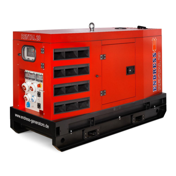
Description of the Generator The components and functionality of the generator are de- scribed in this section. Views of the generator at the on the rear right left front Figure 6-1: Views of the generator Alternator side Connector panel (control panel) Engine side Crane loading lug Forklift pockets... -
Page 20: Components In The Interior (On The Right Side)
Dimensions Components in the interior (on the right side) Figure 6-2: Components in the interior (on the right side) Filling opening (engine oil) Valve lever - drain oil Oil dipstick Fuel pre-filter with a water separator Engine oil filter Fuel pump Tank filling opening Fuel filter 3-way fuel valve with tap... -
Page 21: Components In The Interior (On The Left Side)
Components in the interior (on the left side) Fig. 6-3: Components in the interior (on the left side) (1) Main battery switch Oil suction pump (2) Hose to the oil drain points Air filter Starter battery Status at: June 2016 Rental Line... -
Page 22: Connector Panel (Control Panel)
Dimensions Connector panel (control panel) Fig. 6-4 Connector panel/control panel (1) Control module E-MCS 6.0 Piezo buzzer (acoustic warning) (3) Line and residual current circuit Sub-assembly with a Schuko socket (1 breaker piece) and CEE sockets (4 pieces) Remote start socket EMERGENCY-STOP switch Operating hours counter EMERGENCY-STOP switch... -
Page 23: Control Module E-Mcs 6.0
Control module E-MCS 6.0 Figure 6-5 E-MCS 6.0 Control button of the E-MCS 6.0 Operation displays for the E-MCS 6.0 Item Button Description START button. Only functional in the operating mode MAN. Press this button to initiate the starting process for the engine. STOP button. -
Page 24: Table 6-1 Control Buttons Of The E-Mcs 6.0
Dimensions HORN RESET button (reset horn). Use this button to deactivate the horn output without acknowledging the alarm. MODE LEFT button (mode left). Use this button to alter the operat- ing mode. This button is only functional if the main window is dis- played with the indicator of the currently selected operating mode. -
Page 25: Table 6-2 Operation Displays For The E-Mcs 6.0
LED diode lights up if the MCB (mains network circuit breaker) is switched on. The diode is actuated with the output MCB CLOSE/OPEN (AMF 8/9) or by the signal MCB Feedback (AMF 20/25). Mains voltage OK. The green LED diode lights up if there is a volt- age present from the mains network and its parameters lie within the limit values. - Page 26 Dimensions 3. The History log page shows the history log in the or- der in which the last recording is shown as the first. NOTE: The History pages and Set points are now only available if you select the interface Engineer (not User).
- Page 27 6.1.1.2 Alarms 6.1.1.3 Leaf through the ECU alarms Status at: June 2016 Rental Line...
- Page 28 Dimensions 6.1.1.4 Changing the setting value Rental Line Status at: June 2016...
- Page 29 6.1.1.5 Password display Status at: June 2016 Rental Line...
- Page 30 Dimensions 6.1.1.6 Information window of the controller Rental Line Status at: June 2016...
- Page 31 6.1.1.7 Adjustment of the display contrast Status at: June 2016 Rental Line...
-
Page 32: Preparation For Commissioning
Dimensions Preparation for commissioning Preparation for using the generator is described in this sec- tion. Transporting the generator Proceed as follows to transport the generator. Requirements The following requirements must be met: The generator must be turned off The generator must have cooled down. -
Page 33: Earth The Generator
WARNING! Leaking engine oil and diesel fuel can burn. Prevent leaking of engine oil and diesel. Generator is switched off. Generator has cooled down. Avoid open flames and sparks. WARNING! Leaking engine oil can contaminate the soil and groundwa- ter. -
Page 34: Commissioning
Dimensions Commissioning Starting the generator Requirements The following requirements must be met: checked and tested for electrical safety (12Checking the electrical safety there must be fuel in the tank (Figure 6-2: Components in the interior (on the right side)) ... -
Page 35: Starting The Generator Manually
Starting the generator manually 8.1.1.1 Figure 8-1: Starting the generator manually Selection switch Alternator off/on Mode button Start button Stop button Piezo buzzer (acoustic warning) Display of the operating mode manually Display of the operating mode automati- cally START 1. Move the selection switch into position. -
Page 36: Switching The Generator Off
Dimensions Switching the generator off Proceed as follows to shut down the generator. Fig. 8-2: Switching the generator off Selection switch Alternator off/on Mode button Start button Stop button Piezo buzzer (acoustic warning) Display of the operating mode manually STOP 1. -
Page 37: Connecting Up To Consumers
We request that you only switch off the device using the EMERGENCY-STOP switch in an emergency. Connecting up to consumers WARNING! Electric shocks cause injury or death. Check the functionality of the residual current circuit breaker using the test button 8.1.1.2 You can connect consumers with Schuko or CEE sockets. -
Page 38: Fig. 8-4: Connect Consumers Over A Terminal Strip
Dimensions 8.1.1.3 Connect consumers over a terminal strip WARNING! Electric shocks cause injury or death. L1 L2 L3 N PE The connection to the terminal strip may only be undertaken when supervised by an electrician. Fig. 8-4: Connect consumers over a terminal strip (1) Connection line Strain relief for outer sheath (3) Fixing for the single conductors... - Page 39 Status at: June 2016 Rental Line...
-
Page 40: Fuel Cock / External Fuelling
Dimensions Fuel cock / external fuelling In the course of supplying fuel you can select between the device's own tank and the refuelling device. Fig. 9-1: Fuel cock / fuelling device Switch position Operation EXTERNAL REFUELLING OWN TANK Table 9-1: Switching positions for the fuel cock / fuelling device Establish external fuelling as follows: 1. -
Page 41: Disposal
Observe all local laws and regulations concerning correct disposal of such parts and substances. Your author- ised ENDRESS generator dealer is happy to advise you. Please observe the pertinent environmental protection regu- lations when disposing of the old oil. We recommend bring- ing the oil in a closed container to an old oil collection centre for disposal. -
Page 42: Extended Functions
Dimensions Extended functions Remote start device The generator can be switched on and off over the remote start socket ( ). The diesel engine Fig. 10 1 Remote start socket can be started and stopped using a potential-free external contact. Standard function: Contact assignment 5 and 6 ... -
Page 43: Maintaining The Generator
Maintaining the generator Generator maintenance is described in this section. Only personnel from the manufacturer may carry out mainte- nance or repair work not described in this section. Maintenance plan / maintenance work Carry out all maintenance tasks specified in the maintenance plan according to the specifications in the enclosed operating and maintenance instructions for the engine. -
Page 44: Replacing The Starter Battery
Dimensions Replacing the starter battery 1. Switch off the main battery switch Figure 11-1: Replacing battery 2. Unscrew the battery cable. Push the protective terminal caps back for this purpose and loosen the screws. Al- ways disconnect the cable from the NEGATIVE terminal first and then disconnect the cable from the POSITIVE terminal. -
Page 45: Motor Oil
Observe all local laws and regulations concerning correct disposal of such parts and substances. Your author- ised ENDRESS generator dealer is happy to advise you. Please observe the pertinent environmental protection regu- lations when disposing of the old oil. We recommend bring- ing the oil in a closed container to an old oil collection centre for disposal. -
Page 46: Checking The Electrical Safety
Dimensions Checking the electrical safety Only specifically authorised personnel may check the electri- cal reliability. The electrical reliability must be checked in accordance with the applicable VDE regulations, EN and DIN standards and especially the current version of the accident prevention reg- ulations. -
Page 47: Troubleshooting
Troubleshooting This section describes problems during operation that au- thorized personnel can remove. Each occurring problem is described with its possible cause and the respective corrective measure. The authorised personnel must immediately shut down the generator and inform the responsible and authorised service personnel if a problem cannot be solved with the aid of the following table. -
Page 48: Table 13-1: Problems Arising During Generator Operation
Dimensions Malfunction Possible cause Correction Battery terminals oxi- Clean battery terminals and, if necessary, apply terminal dized. grease. Starter battery is not being Alternator / charge regulator Call service staff. charged. defective. The engine does not rotate. Engine defective. Call service staff. The engine produces white Coolant has found its way into Call service staff... -
Page 49: Technical Specifications
Technical Specifications The technical specifications are described in this section. Table 14-1:Generator technical data Standard terms of Name Value Unit subscription Type ESE … 20 YW 30 YW 35 YW 45 YW 50 YW Nominal output 400V / 3~ (PRP) 17.9 30.5 30.5... - Page 50 Dimensions Rental Line Status at: June 2016...
-
Page 51: Dimensions
Dimensions Status at: June 2016 Rental Line... -
Page 52: Fig. 15-1 Dimensions 20Yw-50Yw
Dimensions Fig. 15-1 Dimensions 20YW-50YW Rental Line Status at: June 2016...
Need help?
Do you have a question about the ESE 30YW/RS and is the answer not in the manual?
Questions and answers