Table of Contents

Related Manuals for Fluke ESA614


Summary of Contents for Fluke ESA614
- Page 1 ESA614 Electrical Safety Analyzer Users Manual FBC-0110 August 2018, Rev.1 © 2018 Fluke Corporation. All rights reserved. Specifications are subject to change without notice. All product names are trademarks of their respective companies.
- Page 2 Fluke Biomedical warrants this instrument against defects in materials and workmanship for one year from the date of original purchase OR two years if at the end of your first year you send the instrument to a Fluke Biomedical service center for calibration.
-
Page 3: Notices
Copyright Release Fluke Biomedical agrees to a limited copyright release that allows you to reproduce manuals and other printed materials for use in service training programs and other technical publications. If you would like other reproductions or distributions, submit a written request to Fluke Biomedical. - Page 4 Fluke Biomedical, we recommend using United Parcel Service, Federal Express, or Air Parcel Post. We also recommend that you insure your shipment for its actual replacement cost. Fluke Biomedical will not be responsible for lost shipments or instruments that are received in damaged condition due to improper packaging or handling.
- Page 5 Restrictions and Liabilities Information in this document is subject to change and does not represent a commitment by Fluke Biomedical. Changes made to the information in this document will be incorporated in new editions of the publication. No responsibility is assumed by Fluke Biomedical for the use or reliability of software or equipment that is not supplied by Fluke Biomedical, or by its affiliated dealers.
-
Page 7: Table Of Contents
Table of Contents Title Page Notices ........................... 3 Introduction ........................1 Intended Use ........................2 Safety Information ......................2 Unpack the Product ......................5 Instrument Familiarization ....................6 How to Hold the Product ....................10 Connect to Line Power ....................10 Turn On the Product ....................... - Page 8 ESA614 Users Manual Set the Date ......................18 Set the Time......................18 Set the GFCI Limit ....................19 Set Polarity Switching Delay ..................19 Set the Date Format ....................19 Set the Time Format ....................20 Set the Language ...................... 20 Set the Beeper ......................
- Page 9 Contents (continued) Measure Voltage ....................... 48 Measure Resistance ....................48 Measure Current ......................49 How to Simulate ECG Waveforms ................. 49 Memory .......................... 51 Test Sequences ......................51 Factory Supplied Test Sequences ................51 How to Make a Test Sequence.................. 53 Make a New Test Sequence .................
- Page 10 ESA614 Users Manual...
-
Page 11: Introduction
• Insulation resistance before you use the Product. • Ground leakage The Fluke Biomedical ESA614 Electrical Safety Analyzer • Chassis leakage (the Product) is a full-featured, compact, portable • Lead to Ground and Lead to Lead leakage analyzer, designed to verify the electrical safety of medical devices. -
Page 12: Intended Use
ESA614 Users Manual Intended Use Safety Information The Product is an electronic signal source and In this manual, a Warning identifies conditions and measurement device for verifying the electrical safety of procedures that are dangerous to the user. A Caution medical devices. - Page 13 Electrical Safety Analyzer Safety Information • Comply with local and national safety • Do not use the Product around explosive codes. Use personal protective gas, vapor, or in damp or wet equipment (approved rubber gloves, face environments. protection, and flame-resistant clothes) •...
- Page 14 ESA614 Users Manual • Only use probes, test leads, and • Replace the mains power cord if the accessories that have the same insulation is damaged or if the insulation measurement category, voltage, and shows signs of wear. amperage ratings as the Product.
-
Page 15: Unpack The Product
Table 1. Symbols (cont.) Carefully unpack all items from the box and check that Symbol Description you have these items: Conforms to European Union directives. • ESA614 Conforms to relevant Australian EMC • Getting Started Manual requirements. • Carrying case •... -
Page 16: Instrument Familiarization
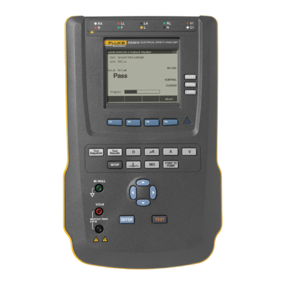
ESA614 Users Manual Instrument Familiarization Figure 1 and Table 2 show the front-panel controls and connections of the Product. gtv116.eps Figure 1. Front-Panel Controls and Connections... - Page 17 Electrical Safety Analyzer Instrument Familiarization Table 2. Top-Panel Controls and Connections Item Name Description Equipment Outlet Controls the configuration of the equipment outlet. Opens and closes the neutral and Configuration Buttons ground connection and reverses the polarity of the neutral and hot connection. Illuminates when high voltage is applied to the ECG/Applied Parts posts, RED V/e/A High Voltage Indicator ...
- Page 18 ESA614 Users Manual Figure 2 and Table 3 describe the side and top-panel connections of the Product. gtv110.eps Figure 2. Side and Top-Panel Connections...
- Page 19 Electrical Safety Analyzer Instrument Familiarization Table 3. Side and Top-Panel Connections Item Name Description Equipment Outlet Specified to the version of the Product, which supplies a DUT connection. USB A Controller Port For external keyboard, barcode reader, or printer. ...
-
Page 20: How To Hold The Product
ESA614 Users Manual Connect to Line Power How to Hold the Product When you move the Product, use the handle on the XWWarning bottom case to hold it. See Figure 3. To prevent possible electrical shock, fire, or personal injury: •... -
Page 21: Turn On The Product
Electrical Safety Analyzer Turn On the Product Use the power cord for your country mains supply that is not more than the voltage or power rating of the product. Connect the cord into the power input connector and then to the mains outlet. Turn On the Product Note To make sure the high-voltage indicator works,... -
Page 22: How To Access The Product Functions
ESA614 Users Manual How to Access the Product Functions For each test and setup function, the Product uses a series of menus to access different Product tests and setup variables. The example shown in Figure 5, shows different leakage current tests along the bottom of the display. -
Page 23: Connect A Dut To The Product
Electrical Safety Analyzer Connect a DUT to the Product Connect a DUT to the Product You can connect a Device Under Test (DUT) a number of different ways for a full electrical safety test. Table 4 shows a DUT connected to the test receptacle, applied parts posts, and a connection to the enclosure or protective earth ground of the DUT. - Page 24 Table 4. DUT Connections gtv113.eps Item Description Connect the ESA614 to grounded mains socket. Connect to protective earth or any exposed conductive surface on the enclosure. Connect the DUT ac power cord to the equipment outlet on the Analyzer.
-
Page 25: Connect A Pc To The Product
Electrical Safety Analyzer Connect a PC to the Product Connect a PC to the Product Plug in an XStick wireless USB dongle to your PC USB To connect the Product to a PC: port. Products available over wireless will be listed by Connect a USB port on your PC or laptop to the Mini B serial number. - Page 26 ESA614 Users Manual gtv129.bmp Figure 6. Product to PC Connection...
-
Page 27: Set Up The Product
Electrical Safety Analyzer Set Up the Product Set Up the Product Set a New Operator Name From the Operator list, push the New softkey. There are a number of Product parameters that are adjusted through the setup function. To access the first Note Setup menu, push . -
Page 28: Delete An Operator Name
ESA614 Users Manual Set the Time Delete an Operator Name From the Setup menu, push or until the Time To delete an operator name: value is highlighted. From the Setup menu, push or until the Push . -
Page 29: Set The Gfci Limit
Electrical Safety Analyzer Set Up the Product Set Polarity Switching Delay Set the GFCI Limit When the test receptacle of the Product is switched, a The GFCI (Ground Fault Current Interrupter) protects the delay can be set to control the actual switch time. To set DUT from short circuits when it is connected to the test the polarity delay: receptacle of the Analyzer. -
Page 30: Set The Time Format
ESA614 Users Manual Set the Time Format Set the Beeper From the Setup menu, push the Instrument Setup To enable or disable the beeper: softkey. From the Setup menu, push the Instrument Setup Push or until the Time Format variable is softkey. -
Page 31: Set Up The Printer
Electrical Safety Analyzer Set Up the Product Set up the Printer Set the Print Header Set the printer type and configure print settings. Use the print header to print a company name or other standard information at the top of each printout. Print Set the Printer Type headers on label printers are limited to 26 characters. -
Page 32: Set The Print Rotation
ESA614 Users Manual Set the Print Rotation Set the Test Interval Set the print rotation for label printers: Set the test interval for label printers. From the Setup menu, push the Printer Settings From the Setup menu, push the Printer Settings softkey. -
Page 33: How To View Instrument Information
Electrical Safety Analyzer How to View Instrument Information How to View Instrument Information Ground Wire Resistance Test The Ground Wire Resistance test measures the To show model number, serial number, firmware version, impedance between the PE terminal of the test receptacle and last calibration date of the Product, push . - Page 34 ESA614 Users Manual WX Warning To do a ground wire resistance test: To prevent electrical shock, remove the null Make sure the power cord from the DUT is post adapter from the ∅/Null jack after a test connected into the test receptacle.
- Page 35 Electrical Safety Analyzer How to Do Electrical Safety Tests Table 5. Ground Wire Resistance Measurement Connections gtv112.eps Item Description Connect to protective earth or any exposed conductive surface on the enclosure. Connect the DUT ac power cord to the equipment outlet on the Analyzer. ...
- Page 36 ESA614 Users Manual Table 6. Schematic Abbreviations Abbreviation Meaning Measurement Device (ESA614 Analyzer) Functional Earth Protective Earth Mains Mains voltage supply Live conductor Neutral conductor Device Under Test DUT_L1 Device Under Test live conductor DUT_L2 Device Under Test neutral conductor...
- Page 37 Electrical Safety Analyzer How to Do Electrical Safety Tests DEVICE UNDER TEST DUT_L1 APPLIED PART DUT_L2 DUT_PE CONDUCTIVE PART TEST LEAD faw26.eps Figure 7. Ground Wire Resistance Measurement Schematic...
-
Page 38: Insulation Resistance Test
ESA614 Users Manual Insulation Resistance Test The five Insulation Resistance Tests measure mains (L1 and L2) to Protective earth, applied parts to Protective earth, mains to applied parts, mains to non-earthed conductive points, and applied parts to non-earthed conductive points. - Page 39 Electrical Safety Analyzer How to Do Electrical Safety Tests DEVICE UNDER TEST DUT_L1 APPLIED PART DUT_L2 DUT_PE CONDUCTIVE PART faw17.eps Figure 9. Mains to Protective-Earth Insulation Resistance Test Schematic...
- Page 40 ESA614 Users Manual DEVICE UNDER TEST DUT_L1 APPLIED PART DUT_L2 DUT_PE CONDUCTIVE PART faw18.eps Figure 10. Applied Parts to Protective-Earth Insulation Test Schematic...
- Page 41 Electrical Safety Analyzer How to Do Electrical Safety Tests DEVICE UNDER TEST DUT_L1 APPLIED PART DUT_L2 DUT_PE CONDUCTIVE PART faw19.eps Figure 11. Mains to Applied-Parts Insulation Test Schematic...
- Page 42 ESA614 Users Manual DEVICE UNDER TEST DUT_L1 APPLIED PART DUT_L2 DUT_PE CONDUCTIVE PART TEST LEAD faw20.eps Figure 12. Mains to Non-Earth Accessible Conductive Points Schematic...
- Page 43 Electrical Safety Analyzer How to Do Electrical Safety Tests DEVICE UNDER TEST DUT_L1 APPLIED PART DUT_L2 DUT_PE CONDUCTIVE PART TEST LEAD faw21.eps Figure 13. Applied Parts to Non-Earth Conductive Points Schematic...
-
Page 44: Equipment Current Test
ESA614 Users Manual Ground Wire Leakage Current Equipment Current Test To measure the current that flows in the protective earth To measure the current consumed by the DUT, push circuit of the DUT, push the Ground Wire softkey from the . - Page 45 Electrical Safety Analyzer How to Do Electrical Safety Tests DEVICE UNDER TEST MAINS DUT_L1 APPLIED PART MAINS DUT_L2 DUT_PE CONDUCTIVE PART faw27a.eps Figure 14. Ground Wire Leakage Current Test Schematic...
-
Page 46: Chassis Leakage Test
ESA614 Users Manual Chassis Leakage Test The Chassis Leakage test can be done with different fault conditions on the test receptacle. Push to switch The Chassis Leakage Test measures the current that the test receptacle between Normal, Off, Reverse, and flows between the enclosure of the DUT and protective Off. - Page 47 Electrical Safety Analyzer How to Do Electrical Safety Tests DEVICE UNDER TEST MAINS DUT_L1 APPLIED PART MAINS DUT_L2 EARTH DUT_PE CONDUCTIVE PART TEST LEAD faw28a.eps Figure 15. Chassis Leakage Current Test Schematic...
-
Page 48: Lead-To-Ground Leakage Test
ESA614 Users Manual The Lead-to-Ground Leakage test can be done with Lead-to-Ground Leakage Test different fault conditions on the test receptacle. Push The Lead-to-Ground Leakage Current test measures the to switch the test receptacle between Normal, Off, current that flows between in one applied part, a group of Reverse, and Off. - Page 49 Electrical Safety Analyzer How to Do Electrical Safety Tests DEVICE UNDER TEST MAINS DUT_L1 APPLIED PART MAINS DUT_L2 EARTH DUT_PE CONDUCTIVE PART LEAD SELECT RELAY* LEAD GND SELECT RELAY (REMOTE ONLY) *Leads not selected are open. gtv29.eps Figure 16. Lead-to-Ground Leakage Current Test Schematic...
-
Page 50: Lead-To-Lead Leakage Tests
ESA614 Users Manual Lead-to-Lead Leakage Tests To measure the leakage current through each applied part or lead and combination of lead connections (all other or between two), push the Lead to Lead softkey from the Leakage Test main menu. Figure 18 shows the electrical connections between the Product and the DUT when it fis107.eps... - Page 51 Electrical Safety Analyzer How to Do Electrical Safety Tests MAINS DEVICE UNDER TEST DUT_L1 APPLIED PART MAINS DUT_L2 EARTH DUT_PE CONDUCTIVE PART + LEAD SELECT RELAY* - LEAD SELECT RELAY* LEAD GND SELECT RELAY* (REMOTE ONLY) *Leads not selected are open. gtv30.eps Figure 18.
-
Page 52: Lead Isolation Leakage Test
ESA614 Users Manual The outlet conditions below apply when you do this test: Push the Select softkey. • Normal Polarity Push the Lead Isolation softkey. • Normal Polarity, Open Neutral Push or to set the desired applied part connection. - Page 53 Electrical Safety Analyzer How to Do Electrical Safety Tests DEVICE UNDER TEST MAINS DUT_L1 APPLIED PART MAINS DUT_L2 DUT_PE CONDUCTIVE PART TEST LEAD MAP (ISOLATION) TRANSFORMER LEAD SELECT RELAY* *Leads not selected are open. gtv31.eps Figure 19. Lead Isolation Leakage Test Schematic...
-
Page 54: How To Use The 1-To-10 Adapter
ESA614 Users Manual The common lead from the Adapter is plugged into the RA How to Use the 1-to-10 Adapter jack (1 jack) of the Product. Using four sheathed test The 1-to-10 Adapter, an optional accessory, increases the leads with alligator clips, connect the two defibrillator... - Page 55 Defibrillator/Pacer ESA614 do not apply more than 30 V dc to the AP (ECG). DEFIB PACER Check unkown connections using a DMM before connecting to the ESA614. 1-to-10 and BJ2ECG Alligator Clips snap adapters Use leads shorted for electrical safety testing only.
- Page 56 ESA614 Users Manual When you do an applied parts test with the AAMI/NFPA-99 standard, the normal connections of RA, LL, LA, and RL are made to their related input jacks. Four adapters from the Universal Snap to Banana Adapter set will be necessary for the first four connections.
- Page 57 Electrical Safety Analyzer How to Use the 1-to-10 Adapter ECG Monitor ESA614 1-to-10 and BJ2ECG snap adapters Use leads shorted for electrical safety testing only. Do not short leads for ECG simulation. gtv121a.eps Figure 21. ECG Lead Connection with 1-to-10 Adapter...
-
Page 58: How To Do Point-To-Point Measurements
ESA614 Users Manual Measure Voltage How to Do Point-To-Point Measurements To make a voltage measurement: The Product can make voltage, resistance, and low current measurements through its Point-to-Point function. Push the Voltage softkey from the Point-To-Point To access the Point-to-Point function menu shown in menu. -
Page 59: Measure Current
Electrical Safety Analyzer How to Simulate ECG Waveforms Measure Current Note If the ECG monitor/interpreter has banana posts, The Product can make dc only, ac only, and ac+dc current use the optional universal snap to banana measurements to a maximum of 10 mA. To do a current adapter to connect to the Product. - Page 60 ESA614 Users Manual ECG Monitor BJ2ECG Adapter gtv115.eps Figure 23. ECG Monitor Connections...
-
Page 61: Memory
Electrical Safety Analyzer Memory Memory To install the memory card: Insert the card with the contacts toward the back. The Product keeps test results data and test sequences on an SD memory card. The memory card holds a Push the card all the way in until you hear it click. minimum of 100 test sequences and 1000 test results. - Page 62 ESA614 Users Manual Table 7. Factory Supplied Test Sequences Test Sequence Description NFPA99 Patient Monitor Class I, 5 ECG NFPA99 Defibrillator Class I, 2 Paddles and 3 ECG NFPA99 Infusion Device Class II, 1 No AP NFPA99 Ultrasound Device Class I, 1 Probe...
-
Page 63: How To Make A Test Sequence
Electrical Safety Analyzer Test Sequences How to Make a Test Sequence Note A USB keyboard or barcode reader can be used You can make a new test sequence from a different test to type in the AP name. sequence or make a new one. If the DUT does not have applied parts, push the Next Make a New Test Sequence Step softkey to skip the applied parts configuration. - Page 64 ESA614 Users Manual Edit test settings. Table 8 is a list of test settings with their descriptions and default values. gtv127.bmp Figure 24. Input Position ICON To set one of the test settings, push or to highlight a test setting and push . After you To put a DUT applied part on each of the Product change the setting, push the Done softkey.
- Page 65 Electrical Safety Analyzer Test Sequences Table 8. Test Settings for Test Sequences Default Test Setting Description Value If set to Yes, delays the start of the test by the time set in the Power on delay Pause after power on parameter when power is applied to the DUT.
- Page 66 ESA614 Users Manual Table 0-8. Test Settings for Test Sequences (cont.) Default Test Setting Description Value Multiple PE Tests If set to Yes, the Product prompts you to repeat PE tests or continue. Multiple Non-Earth If set to Yes, the Product prompts you to repeat non-earth leakage tests or Leakage continue.
-
Page 67: Make A Test Sequence From A Test Sequence In The Test Library
Electrical Safety Analyzer Test Sequences Make a Test Sequence from a Test Sequence in the Push the Edit softkey. Test Library Go through each setup step of the test sequence and accept the parameters or change them for the new To make a test sequence from a test sequence already in test sequence. -
Page 68: Do A Test Sequence
ESA614 Users Manual Do a Test Sequence Note A USB keyboard or barcode reader can be used To do a test sequence: to type in the DUT information. You can use a Push to show the test sequence screen. -
Page 69: Show Test Results
Electrical Safety Analyzer Test Sequences Show Test Results Print Test Results To show test results in the display: With a PCL5 compatible printer connected to the USB A Controller Port, you can print a test results record on a Push . letter or A4 sheet of paper. -
Page 70: Delete A Set Of Test Results
ESA614 Users Manual Delete a Set of Test Results Maintenance To delete a test result: XW Warning Push . To prevent possible electrical shock, fire, or personal injury: Push or to highlight a test result name. • Turn off the Product and remove the Note mains power cord. -
Page 71: Fuse Test And Fuse Replacement
Applicable fuse ratings are posted on the case bottom label of the Product. Table 9 is a list of available fuses with Fluke Biomedical part numbers. Reinstall the fuse door and secure it with the screw. -
Page 72: How To Clean The Product
ESA614 Users Manual How to Clean the Product XW Warning To prevent electric shock, do not clean the Product plugged into mains or attached to a DUT. W Caution Do not pour fluid onto the Product surface. Fluid in the electrical circuitry can cause the Product to fail. -
Page 73: Replaceable Parts
Replaceable Parts Table 9 is a list of replaceable parts for the Product. Table 9. Replaceable Parts Fluke Biomedical Item Part Number ESA614 Getting Started Manual 5006602 15 A Mains Power Cord 2238644 Null Post Adapter 3326842 Ansur, CD with demo version... -
Page 74: Accessories
ESA614 Users Manual Accessories Table 10 is a list of available accessories for the Product. Table 10. Accessories Item Fluke Biomedical Part Number Test Leads with Retractable Sheath 1903307 Ground Pin Adapters 2242165 1–to–10 ECG Adapter 3392119 Universal Snap to Banana Adapter... -
Page 75: Specifications
Electrical Safety Analyzer Specifications Specifications Temperature Operating ............10 °C to 40 °C (50 °F to 104 °F) Storage ..............-20 °C to 60 °C (-4 °F to 140 °F) Humidity ..............10 % to 90 % non-condensing Altitude 100 V/115 V ac mains supply voltage ....5000 m 230 V ac mains supply voltage ...... -
Page 76: Detailed Specifications
ESA614 Users Manual Safety General ............... IEC 61010-1: Overvoltage Category II, Pollution Degree 2 Measurement ............IEC 61010-2-030: CAT II 300 V IP Rating ..............IEC 60529: IP20 Electromagnetic Compatibility (EMC) International ............IEC 61326-1: Basic Electromagnetic Environment CISPR 11: Group 1, Class A Group 1: Equipment has intentionally generated and/or uses conductively-coupled radio frequency energy that is necessary for the internal function of the equipment itself. - Page 77 Electrical Safety Analyzer Detailed Specifications Ground Wire Resistance Modes..............2-Wire Test Current ............>200 mA ac Range ..............0.000 Ω to 2.000 Ω Accuracy.............. ±(2 % of reading + 0.015 Ω) Equipment Current Range ..............0.0 A to 20.0 A ac rms Accuracy..............
- Page 78 ESA614 Users Manual Accuracy DC to 1 kHz ............. ±(1 % of reading + (1 μA or 1 LSD, whichever is greater)) 1 kHz to 100 kHz ..........±(2 % of reading + (1 μA or 1 LSD, whichever is greater)) 1 kHz to 5 kHz (current >...
- Page 79 Electrical Safety Analyzer Detailed Specifications ECG Performance Waveforms Accuracy Frequency ............±2 % Amplitude ............±5 % of 2 Hz square wave only, fixed @ 1 mV Lead II configuration Waveforms ECG Complex ..........30, 60, 120, 180, and 240 BPM Ventricular Fibrillation Square wave (50 % duty cycle) .......
- Page 80 ESA614 Users Manual...
Need help?
Do you have a question about the ESA614 and is the answer not in the manual?
Questions and answers