Table of Contents

Related Manuals for Fluke ESA615


Summary of Contents for Fluke ESA615
- Page 1 ESA615 Electrical Safety Analyzer Users Manual FBC-0026 February 2012, Rev. 1 © 2012 Fluke Corporation. All rights reserved. Specifications are subject to change without notice. All product names are trademarks of their respective companies.
- Page 2 Fluke Biomedical warrants this instrument against defects in materials and workmanship for one year from the date of original purchase OR two years if at the end of your first year you send the instrument to a Fluke Biomedical service center for calibration.
-
Page 3: Unpacking And Inspection
Copyright Release Fluke Biomedical agrees to a limited copyright release that allows you to reproduce manuals and other printed materials for use in service training programs and other technical publications. If you would like other reproductions or distributions, submit a written request to Fluke Biomedical. - Page 4 To ensure the accuracy of the Product is maintained at a high level, Fluke Biomedical recommends the product be calibrated at least once every 12 months. Calibration must be done by qualified personnel. Contact your local Fluke Biomedical representative for calibration.
- Page 5 Restrictions and Liabilities Information in this document is subject to change and does not represent a commitment by Fluke Biomedical. Changes made to the information in this document will be incorporated in new editions of the publication. No responsibility is assumed by Fluke Biomedical for the use or reliability of software or equipment that is not supplied by Fluke Biomedical, or by its affiliated dealers.
- Page 7 Table of Contents Title Page Introduction ........................1 Intended Use........................3 Safety Information ......................3 Unpack the Product......................5 Instrument Familiarization ....................6 How to Hold the Product ....................10 How to Connect to Line Power ..................10 How to Connect a DUT to the Product ................11 How to Turn the Product On...................
- Page 8 ESA615 Users Manual Set the Test Standard ....................16 Set the GFCI Limit ....................16 Set Polarity Switching Delay ..................17 Set the Date Format....................17 Set the Time Format ....................17 Set the Language...................... 17 Set the Beeper ......................18 Set the Display Contrast ...................
- Page 9 Contents (continued) Measure Resistance....................57 Measure Current......................58 How to Simulate ECG Waveforms ................. 58 Memory .......................... 61 Test Sequences ......................61 Factory Supplied Test Sequences................61 How to Make a Test Sequence.................. 64 Make a New Test Sequence................. 64 Make a Test Sequence from a Test Sequence in the Test Library .......
- Page 10 ESA615 Users Manual...
-
Page 11: List Of Tables
List of Tables Table Title Page Symbols..........................2 Top-Panel Controls and Connections..................6 Side and Top-Panel Connections..................9 Schematic Abbreviations ....................... 23 Test Names Based on Selected Standard................31 Factory Supplied Test Sequences..................62 Test Settings for Test Sequences ..................66 Replaceable Parts ......................... - Page 12 ESA615 Users Manual...
-
Page 13: List Of Figures
List of Figures Figure Title Page Front-Panel Controls and Connections ................. 6 Side and Top-Panel Connections..................8 Product Handle........................10 Product Ready for Operation....................11 DUT Connections to the Product................... 12 Leakage Current Menu......................13 Setup Menu ........................... 14 Operator List Screen ......................14 Mains Voltage Test Menu...................... - Page 14 ESA615 Users Manual Mains to Applied-Parts Insulation Test Schematic..............28 Mains to Non-Earth Accessible Conductive Points Schematic ..........29 Applied Parts to Non-Earth Conductive Points Schematic............ 30 Leakage Current Main Menu ....................32 Earth Leakage Current Test Schematic ................34 Enclosure Leakage Current Test Schematic.................
-
Page 15: Introduction
“safety information” • Ground Wire (Protective Earth) resistance before you use the Product. • Equipment current The Fluke Biomedical ESA615 Electrical Safety Analyzer • Insulation resistance (the Product) is a full-featured, compact, portable • Ground (Earth) leakage analyzer, designed to verify the electrical safety of medical devices. - Page 16 Conforms to relevant Australian EMC requirements. Conforms to European Union directives. Do not dispose of this product as unsorted municipal waste. Go to Fluke’s website for recycling information. IEC Measurement Category II – CAT II equipment designed to protect against...
-
Page 17: Safety Information
Electrical Safety Analyzer Intended Use Safety Information Intended Use In this manual, a Warning identifies conditions and The Product is an electronic signal source and procedures that are dangerous to the user. A Caution measurement device for verifying the electrical safety of identifies conditions and procedures that can cause medical devices. - Page 18 ESA615 Users Manual • • Do not use test leads if they are Remove the null post adapter from the ∅/Null jack after a test lead zero is damaged. Examine the test leads for damaged insulation, exposed metal, or if performed.
-
Page 19: Unpack The Product
Carefully unpack all items from the box and check that shows signs of wear. you have these items: • Comply with local and national safety • codes. Use personal protective ESA615 equipment (approved rubber gloves, face • Getting Started Manual protection, and flame-resistant clothes) • Users Manual CD to prevent shock and arc blast injury •... -
Page 20: Instrument Familiarization
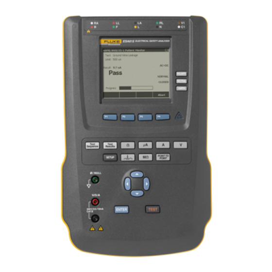
ESA615 Users Manual Instrument Familiarization Figure 1 and Table 2 show the front-panel controls and connections of the Product. gtv116.eps Figure 1. Front-Panel Controls and Connections... - Page 21 Electrical Safety Analyzer Instrument Familiarization Table 2. Top-Panel Controls and Connections Item Name Description Equipment Outlet Controls the configuration of the equipment outlet. Opens and closes the neutral and Configuration Buttons ground connection and reverses the polarity of the neutral and hot connection. Illuminates when high voltage is applied to the ECG/Applied Parts posts or L1 and High Voltage Indicator L2 of the Test Receptacle.
- Page 22 ESA615 Users Manual Figure 2 and Table 3 describe the side and top-panel connections of the Product. gtv110.eps Figure 2. Side and Top-Panel Connections...
- Page 23 Electrical Safety Analyzer Instrument Familiarization Table 3. Side and Top-Panel Connections Item Name Description Equipment outlet, specified to the version of the Product, which supplies a DUT Equipment Outlet connection. USB A Controller Port For external keyboard or barcode reader. USB Device Port Digital connection to control the Product from a PC or instrument controller.
-
Page 24: How To Hold The Product
ESA615 Users Manual How to Connect to Line Power How to Hold the Product When you move the Product, use the handle on the XWWarning bottom case to hold it. See Figure 3. To prevent possible electrical shock, fire, or personal injury: •... -
Page 25: How To Connect A Dut To The Product
Electrical Safety Analyzer How to Connect a DUT to the Product The Product is intended for use with single-phase, grounded power. It is not intended for dual, split-phase or three-phase power configurations. It can be used with a power system that supplies the correct voltages for single-phase and is grounded, or is an isolated power system. - Page 26 ESA615 Users Manual To protective earth or any exposed conductive surface on the enclosure gtv113.eps Figure 5. DUT Connections to the Product...
-
Page 27: How To Access The Product Functions
Electrical Safety Analyzer How to Access the Product Functions The self-test measures the ac mains input for correct polarity, ground integrity and voltage level. The high voltage indicator illuminates briefly during the self test. If the polarity is reversed, the Product shows this condition and sets the polarity to be reversed internally. -
Page 28: How To Set Up The Product
ESA615 Users Manual How to Set Up the Product There are a number of Product parameters that are adjusted through the setup function. To access the first Setup menu shown in Figure 7, push Q. gtv123.jpg Figure 8. Operator List Screen... -
Page 29: Delete An Operator Name
Electrical Safety Analyzer How to Set Up the Product Set a New Operator Name Delete an Operator Name From the Operator list, push the New softkey. To delete an operator name: From the setup menu, push G or H until the Note Operator name is highlighted. -
Page 30: Set The Date
ESA615 Users Manual Set the Date Push the Done softkey. From the setup menu, push G or H until the Date value Note is highlighted. Push the Backspace softkey to delete the last character in the date field. Push e. -
Page 31: Set Polarity Switching Delay
Electrical Safety Analyzer How to Set Up the Product Set Polarity Switching Delay Push e. When the test receptacle of the Product is switched, a Push G or H to highlight 12 Hour or 24 Hour. delay can be set to control the actual switch time. To set Push e. -
Page 32: Set The Beeper
ESA615 Users Manual Set the Beeper How to View Instrument Information To enable or disable the beeper: To show model number, serial number, firmware version, From the setup menu, push the Instrument Setup and last calibration date of the Product, push Q. Next softkey. -
Page 33: Set The Test Standard
Electrical Safety Analyzer How to Do Electrical Safety Tests Set the Test Standard The electrical safety tests in the Product are specified by different safety standards: AAMI ES1/NFPA99, IEC62353, IEC60601-1, and AN/NZS 3551. AAMI is set as the default standard. To select different standard: From the setup menu, push H until the Standard variable is highlighted. -
Page 34: Ground Wire (Protective Earth) Resistance Test
ESA615 Users Manual null post adapter in the ∅/Null jack, and clamp the Ground Wire (Protective Earth) Resistance Test alligator clip to the null post adapter. The Ground Wire (Protective Earth) Resistance test measures the impedance between the PE terminal of the... - Page 35 Electrical Safety Analyzer How to Do Electrical Safety Tests After you make the connections to the DUT, the Figure 11 shows the electrical connections between the measured resistance shows in the display. See Product and the DUT. Table 4 is a list of the abbreviations Figure 10.
- Page 36 ESA615 Users Manual To protective earth or any exposed conductive surface on the enclosure gtv112.eps Figure 11. Ground Wire (Protective Earth) Resistance Measurement Connections...
- Page 37 Electrical Safety Analyzer How to Do Electrical Safety Tests Table 4. Schematic Abbreviations Abbreviation Meaning Measurement Device (ESA615 Analyzer) Functional Earth Protective Earth Mains Mains voltage supply Live conductor Neutral conductor Device Under Test DUT_L1 Device Under Test live conductor...
- Page 38 ESA615 Users Manual DEVICE UNDER TEST DUT_L1 APPLIED PART DUT_L2 DUT_PE CONDUCTIVE PART TEST LEAD faw26.eps Figure 12. Ground Wire (Protective Earth) Resistance Measurement Schematic...
-
Page 39: Insulation Resistance Test
Electrical Safety Analyzer How to Do Electrical Safety Tests Insulation Resistance Test The five Insulation Resistance Tests measure mains (L1 & L2) to Protective earth, applied parts to Protective earth, mains to applied parts, mains to non-earthed conductive points, and applied parts to non-earthed conductive points. To access the Insulation Resistance Test menu, push M. - Page 40 ESA615 Users Manual DEVICE UNDER TEST DUT_L1 APPLIED PART DUT_L2 DUT_PE CONDUCTIVE PART faw17.eps Figure 14. Mains to Protective-Earth Insulation Resistance Test Schematic...
- Page 41 Electrical Safety Analyzer How to Do Electrical Safety Tests DEVICE UNDER TEST DUT_L1 APPLIED PART DUT_L2 DUT_PE CONDUCTIVE PART faw18.eps Figure 15. Applied Parts to Protective-Earth Insulation Test Schematic...
- Page 42 ESA615 Users Manual DEVICE UNDER TEST DUT_L1 APPLIED PART DUT_L2 DUT_PE CONDUCTIVE PART faw19.eps Figure 16. Mains to Applied-Parts Insulation Test Schematic...
- Page 43 Electrical Safety Analyzer How to Do Electrical Safety Tests DEVICE UNDER TEST DUT_L1 APPLIED PART DUT_L2 DUT_PE CONDUCTIVE PART TEST LEAD faw20.eps Figure 17. Mains to Non-Earth Accessible Conductive Points Schematic...
- Page 44 ESA615 Users Manual DEVICE UNDER TEST DUT_L1 APPLIED PART DUT_L2 DUT_PE CONDUCTIVE PART TEST LEAD faw21.eps Figure 18. Applied Parts to Non-Earth Conductive Points Schematic...
-
Page 45: Equipment Current Test
Electrical Safety Analyzer How to Do Electrical Safety Tests Equipment Current Test on each connected applied part and combinations of connected applied parts. To measure the current consumed by the DUT, push A. The Product shows the current that flows through The available leakage tests are set by the standard you the mains connections of the test receptacle. -
Page 46: Earth Leakage Current
ESA615 Users Manual Earth Leakage Current Note The Ground Wire (Earth) Leakage test is available for AAMI, 60601, and not IEC 62353. To measure the current that flows in the protective earth circuit of the DUT, push the Ground Wire softkey from the leakage current main menu. - Page 47 Electrical Safety Analyzer How to Do Electrical Safety Tests The outlet conditions below apply when you do this test: • Normal Polarity • Normal Polarity, Open Neutral • Reversed Polarity • Reversed Polarity, Open Neutral IEC60601-1 specifies that the applied parts must be connected for this measurement.
- Page 48 ESA615 Users Manual DEVICE UNDER TEST MAINS DUT_L1 APPLIED PART MAINS DUT_L2 DUT_PE CONDUCTIVE PART APPLIED PART faw27.eps Figure 20. Earth Leakage Current Test Schematic Note Ground wire leakage is the same schematic without the Applied Parts switch.
-
Page 49: Chassis (Enclosure) Leakage Test
Electrical Safety Analyzer How to Do Electrical Safety Tests Chassis (Enclosure) Leakage Test • Normal Polarity, Open Neutral • Reversed Polarity Note • Reversed Polarity, Open Earth The Chassis (Enclosure) Leakage test is only • Reversed Polarity, Open Neutral available for the IEC60601 or ANSI/AAMI ES1 1993 standard selections. - Page 50 ESA615 Users Manual DEVICE UNDER TEST MAINS DUT_L1 APPLIED PART MAINS DUT_L2 EARTH DUT_PE CONDUCTIVE PART TEST LEAD APPLIED PART faw28.eps Figure 21. Enclosure Leakage Current Test Schematic...
-
Page 51: Lead-To-Ground (Patient) Leakage Test
Electrical Safety Analyzer How to Do Electrical Safety Tests Lead-to-Ground (Patient) Leakage Test P to switch the test receptacle between Normal, Off, Reverse, and Off. Push N to open and close the Note neutral connection to the receptacle. Push D to open The Lead-to-Ground (Patient) Leakage Current and close the earth connection in the receptacle. - Page 52 ESA615 Users Manual DEVICE UNDER TEST MAINS DUT_L1 APPLIED PART MAINS DUT_L2 EARTH DUT_PE CONDUCTIVE PART LEAD SELECT RELAY* LEAD GND SELECT RELAY (REMOTE ONLY) *Leads not selected are open. gtv29.eps Figure 22. Lead-to-Ground (Patient) Leakage Current Test Schematic...
-
Page 53: Lead-To-Lead (Patient Auxiliary) Leakage Tests
Electrical Safety Analyzer How to Do Electrical Safety Tests Lead-to-Lead (Patient Auxiliary) Leakage Tests Note The Lead-to-Lead (Patient Auxiliary) leakage test is available when the IEC60601 or ANSI/AAMI ES1-1993 standard is selected. To measure the leakage current through each applied part fis107.eps or lead and combination of lead connections (all other or Figure 23. - Page 54 ESA615 Users Manual MAINS DEVICE UNDER TEST DUT_L1 APPLIED PART MAINS DUT_L2 EARTH DUT_PE CONDUCTIVE PART + LEAD SELECT RELAY* - LEAD SELECT RELAY* LEAD GND SELECT RELAY* (REMOTE ONLY) *Leads not selected are open. gtv30.eps Figure 24. Lead-to-Lead (Patient Auxiliary) Leakage Current Test Schematic...
-
Page 55: Lead Isolation (Mains On Applied Part) Map Leakage Test
Electrical Safety Analyzer How to Do Electrical Safety Tests The outlet conditions below apply when you do this test: Push B. • Normal Polarity Push the More softkey. • Normal Polarity, Open Neutral Set the applied part groupings with G and H. •... - Page 56 ESA615 Users Manual Push E and F to scroll through the applied part connections or groupings. Push T for each connection configuration to thoroughly test the DUT. The outlet conditions below apply when you do this test: • Normal Polarity •...
- Page 57 Electrical Safety Analyzer How to Do Electrical Safety Tests DEVICE UNDER TEST MAINS DUT_L1 APPLIED PART MAINS DUT_L2 DUT_PE CONDUCTIVE PART TEST LEAD MAP (ISOLATION) TRANSFORMER LEAD SELECT RELAY* *Leads not selected are open. gtv31.eps Figure 25. Lead Isolation (Mains On Applied Parts) Leakage Test Schematic...
-
Page 58: Alternative Equipment Leakage Test
ESA615 Users Manual Alternative Equipment Leakage Test The outlet conditions below apply when you do this test: • Closed Earth Note • Open Earth The alternative equipment leakage test is available when the EN62353 standard is Note selected. If there are more than five applied parts to... - Page 59 Electrical Safety Analyzer How to Do Electrical Safety Tests DEVICE UNDER TEST DUT_L1 APPLIED PART DUT_L2 CONDUCTIVE PART DUT_PE TEST LEAD faw22.eps Figure 26. Alternative Equipment Leakage Current Test Schematic...
-
Page 60: Direct Equipment Leakage Test
ESA615 Users Manual To do an alternative applied part leakage test: The Direct Equipment Leakage Current test measures the leakage current between all applied parts and the exposed Push B. conductive surface on the housing to mains earth. Push the More softkey. - Page 61 Electrical Safety Analyzer How to Do Electrical Safety Tests DEVICE UNDER TEST DUT_L1 APPLIED LEAD PART SELECT RELAY* DUT_L2 *Leads not selected are open. DUT_PE CONDUCTIVE PART TEST LEAD gtv23.eps Figure 27. Alternative Applied Part Leakage Test Schematic...
-
Page 62: Direct Applied Part Leakage Test
ESA615 Users Manual Direct Applied Part Leakage Test Figure 29 shows the electrical connections between the Product and the DUT for a Direct Applied Part Leakage Note Current Test. The Direct Applied Part Leakage test is available The outlet conditions below apply when you do this test: when the EN62353 standard is selected. - Page 63 Electrical Safety Analyzer How to Do Electrical Safety Tests MAINS DEVICE UNDER TEST DUT_L1 APPLIED PART MAINS DUT_L2 DUT_PE CONDUCTIVE PART TEST LEAD faw24.eps Figure 28. Direct Equipment Leakage Test Schematic...
- Page 64 ESA615 Users Manual DEVICE UNDER TEST MAINS DUT_L1 LEAD APPLIED SELECT PART RELAY* MAINS DUT_L2 *Leads not selected are open. DUT_PE CONDUCTIVE PART gtv25.eps Figure 29. Direct Applied Parts Leakage Current Test Schematic...
-
Page 65: Differential Leakage Current Test
Electrical Safety Analyzer How to Do Electrical Safety Tests Differential Leakage Current Test Note The Differential Leakage Current test is available when the EN62353 standard is selected. The differential leakage current test measures the magnitudes of the differential current that flows in the Equipment Outlet live and neutral, with power applied to the equipment outlet. - Page 66 ESA615 Users Manual DEVICE UNDER TEST MAINS DUT_L1 APPLIED PART MAINS DUT_L2 EARTH DUT_PE CONDUCTIVE PART TEST LEAD gtv32.eps Figure 30. Differential Leakage Current Test Schematic...
-
Page 67: How To Use The 1210 Adapter
Electrical Safety Analyzer How to Use the 1210 Adapter How to Use the 1210 Adapter The 1210 Adapter, an optional accessory, increases the number of lead or applied parts connections to the Product from 5 to 14. The adapter connects a maximum of 10 leads together into a one lead that is connected to one of the input jacks of the Product. - Page 68 ESA615 Users Manual Caution: To prevent damage to the Product, Defibrillator/Pacer ESA615 do not apply more than 30 V dc to the AP (ECG). DEFIB PACER 1210 gtv120.eps Figure 31. 1210 Adapter Connections...
- Page 69 Electrical Safety Analyzer How to Use the 1210 Adapter When you do an applied parts test with the AAMI/NFPA- 99 standard, the normal connections of RA, LL, LA, and RL are made to their related input jacks. Four adapters from the Universal Snap to Banana Adapter set will be necessary for the first four connections.
- Page 70 ESA615 Users Manual ECG Monitor ESA615 1210 gtv121.eps Figure 32. EGC Lead Connection with 1210 Adapter...
-
Page 71: How To Do Point-To-Point Measurements
Electrical Safety Analyzer How to Do Point-To-Point Measurements How to Do Point-To-Point Measurements The Product measures a maximum of 300 volts ac. Measure Resistance The Product can make voltage, resistance, and low current measurements through its Point-to-Point function. To make a resistance measurement: To access the Point-to-Point function menu shown in Push the Resistance softkey from the Point-To-Point Figure 33, push R. -
Page 72: Measure Current
ESA615 Users Manual Measure Current To access the ECG Simulation Waveform menu shown in Figure 34, push C. From this menu, a number of The Product can make dc only, ac only, and ac+dc current waveforms are set through F1, and the rate or frequency measurements to a maximum of 10 mA. - Page 73 Electrical Safety Analyzer How to Simulate ECG Waveforms For all waveforms but VFIB and Triangle, the rate or frequency of the waveform is adjusted through the Frequency or Rate softkey. For some waveforms, there are more than two frequency or rate selections. For those waveforms, push the Frequency or Rate softkey to open a scroll box above the softkey label with K next to it.
- Page 74 ESA615 Users Manual ECG Monitor BJ2ECG Adapter gtv115.eps Figure 35. ECG Monitor Connections...
-
Page 75: Test Sequences
Electrical Safety Analyzer Memory Memory test sequence that is already in the test library and change it to make a new test sequence. The test sequences and The Product keeps test results data and test sequences test results are kept on the memory card. on an SD memory card. - Page 76 ESA615 Users Manual Table 6. Factory Supplied Test Sequences Test Sequence Description 60601-1 Patient Monitor Ed., Class I, 5 ECG 60601-1 Defibrillator Ed., Class I, 2 Paddles and 3 ECG 60601-1 Infusion Device Ed., Class II, 1 Syringe 60601-1 Ultrasound Device Ed., Class I, 1 Probe...
- Page 77 Electrical Safety Analyzer Test Sequences Table 6. Factory Supplied Test Sequences (cont.) Test Sequence Description NFPA-99 (Hospital) Ultrasound Device Class I, 1 Probe NFPA-99 (Hospital) Generic Device Class I, No AP ANSI/AAMI ES-1 Patient Monitor Class I, 5 ECG ANSI/AAMI ES-1 Defibrillator Class I, 2 Paddles and 3 ECG ANSI/AAMI ES-1 Infusion Device Class II, 1 Syringe...
-
Page 78: How To Make A Test Sequence
ESA615 Users Manual How to Make a Test Sequence parts, you can use the 1210 adapter. See the How to Use the 1210 Adapter section to learn more. You can make a new test sequence from a different test If you attach multiple applied parts to one input, then sequence or make a new one. - Page 79 Electrical Safety Analyzer Test Sequences Push the Done softkey to complete the applied part configuration. To edit an applied part configuration, use G or H to highlight the A.P. configuration and push e. Edit test settings. Table 7 is a list of test settings with their descriptions and default values.
- Page 80 ESA615 Users Manual Table 7. Test Settings for Test Sequences Default Test Setting Description Value Pause after power on If set to yes, delays the start of the test by the time set in the Power on delay parameter when power is applied to the DUT.
- Page 81 Electrical Safety Analyzer Test Sequences Table 7. Test Settings for Test Sequences (cont.) Default Test Setting Description Value Multiple PE Tests If set to Yes, the Product prompts you to repeat PE tests or continue. Multiple Results When set to Store all, all results are put into the test results. If set to Store storage worst/last, only the worst measured value is put into the test results.
-
Page 82: Make A Test Sequence From A Test Sequence In The Test Library
ESA615 Users Manual Make a Test Sequence from a Test Sequence in the Edit a Test Sequence Test Library To change one or more steps of a test sequence: To make a test sequence from a test sequence already in Push s. -
Page 83: Do A Test Sequence
Electrical Safety Analyzer Test Sequences Do a Test Sequence Note To see the details of the test sequence you are To do a test sequence: about to start, push the Sequence Details Push s to show the test sequence screen in softkey. -
Page 84: Show Test Results
ESA615 Users Manual When the test sequence step is a visual inspection, you Push the Back softkey to go back to the test results must push the Pass, Fail, or N/A softkey to move on to list. the subsequent test step. -
Page 85: Maintenance
Electrical Safety Analyzer Maintenance Maintenance Fuse Test and Fuse Replacement XW Warning XW Warning To prevent electric shock, remove all power To prevent possible electrical shock, fire, or cords and test leads from the Product before personal injury: you open the fuse door. •... -
Page 86: How To Clean The Product
Applicable fuse ratings are posted on the case bottom label of the Product. Table 8 is a list of available fuses with Fluke Biomedical part numbers. Reinstall the fuse door and secure it with the screw. -
Page 87: Replaceable Parts
Electrical Safety Analyzer Replaceable Parts Replaceable Parts Table 8 is a list of replaceable parts for the Product. Table 8. Replaceable Parts Item Fluke Biomedical Part Number ESA615 Getting Started Manual 4105845 ESA615 Users Manual CD 4105850 USA/Japan 2238680 2238596... - Page 88 ESA615 Users Manual Table 8. Replaceable Parts (cont.) Item Fluke Biomedical Part Number 5-to-5 Banana jack to ECG (BJ2ECG) adapter 3359538 Carrying Case 2248650 Data Transfer Cable 4034393 USA-115, Japan WT20A 250V Fuse (Time Lag), 1¼″ x ¼″ 2183691 Australia, China, 109298 WT10A 250V Fuse (Time Lag), 1¼″...
-
Page 89: Accessories
Electrical Safety Analyzer Accessories Accessories Table 9 is a list of available accessories for the Product. Table 9. Accessories Item Fluke Biomedical Part Number Test Leads with Retractable Sheath 1903307 Ground Pin Adapters 2242165 1–to–10 ECG Adapter 3392119 Universal Snap to Banana Adapter... -
Page 90: Specifications
ESA615 Users Manual Specifications Temperature Operating ............10 °C to 40 °C (50 °F to 104 °F) Storage ............... -20 °C to 60 °C (-4 °F to 140 °F) Humidity..............10 % to 90 % non-condensing Altitude 120 V ac mains supply voltage ......5000 m 230 V ac mains supply voltage ...... -
Page 91: Detailed Specifications
Electrical Safety Analyzer Detailed Specifications Detailed Specifications Test Standard Selections ........ANSI/AAMI ES-1, IEC62353, IEC60601-1, and AN/NZS 3551 Voltage Ranges (Mains voltage) ........90.0 V to 132.0 V ac rms 180.0 V to 264.0 V ac rms Range (Point-to-point voltage) ......0.0 V to 300.0 V ac rms Accuracy..............±(2 % of reading + 0.2 V) Earth Resistance Modes..............2-Wire... - Page 92 ESA615 Users Manual Patient Load Selection ........AAMI ES1-1993 Fig. 1 IEC 60601: Fig. 15 Crest factor ............≤3 Ranges..............0.0 μA to 199.9 μA 200 μA to 1999 μA 2.00 mA to 10.00 mA Accuracy DC to 1 kHz............. ±(1 % of reading + (1 μA or 1 LSD, whichever is greater)) 1 kHz to 100 kHz..........
- Page 93 Electrical Safety Analyzer Detailed Specifications Insulation resistance Ranges ..............0.5 to 20.0 MΩ 20.0 to 100.0 MΩ Accuracy 20 MΩ Range ..........±(2 % of reading + 0.2 MΩ) 100 MΩ Range ..........±(7.5 % of reading + 0.2 MΩ) Source test voltage ..........500 or 250 V dc (+20 %, -0 %) 2.0 ±0.25 mA short-circuit current Maximum load capacitance.........1 μF ECG Performance Waveforms Accuracy...
- Page 94 ESA615 Users Manual Factory-Supplied Test Sequences 60601-1 2 Edition Patient Monitor 60601-1 2 Edition Defibrillator 60601-1 2 Edition Infusion Pump 60601-1 2 Edition Ultrasound Device 60601-1 2 Edition Generic Edition 60601-1 2 Edition System 62353 Patient Monitor 62353 Defibrillator 62353 Infusion Pump...
Need help?
Do you have a question about the ESA615 and is the answer not in the manual?
Questions and answers