Chapters
Table of Contents

Related Manuals for New England Arbors Elysium


Summary of Contents for New England Arbors Elysium
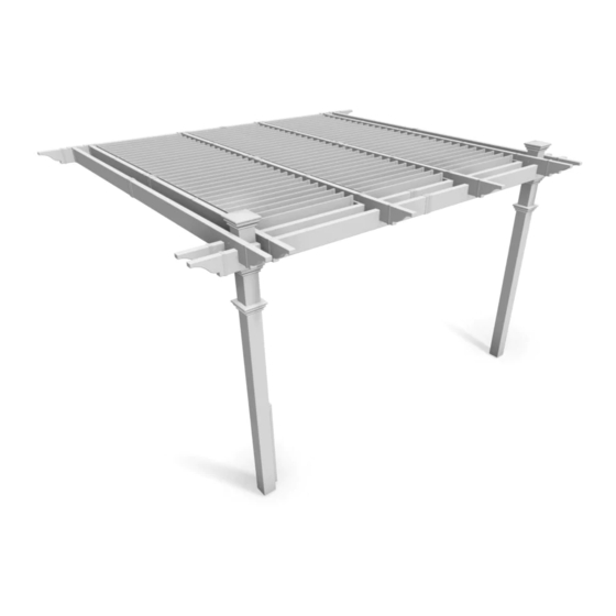
- Page 1 12 x 12 Flat Top Attached Louvered Pergola A S S E M B L Y G U I D E Elysium Model: O P T I O N A L A C C E S S O R I E S : •...
- Page 2 Ta b l e o f Co n t e n t s PAGE 12 x 12 Flat Top Attached Louvered Pergola Introduction & Overview……………………………..........………..Pergola Materials Overview……………………….
-
Page 3: Introduction & Overview
1 800 282 9346,(Mon to Fri 8:00 A.M to 4:00 P.M. Planning & Preparing EST). The Elysium Pergola is designed to be attached to an existing structure such as your house. Please follow this instructions closely and plan ahead to avoid confusions and issues during installation. - Page 4 Elysium Pergola Materials Overview www.newenglandarbors.com 1. Post Caps (2) 11. One Way 4”x4 “ Internal Wood Post Guides (4) 2. Main Column Tops (2) 12. Louver Turn Bar (1) 3. Post Trims (4) 13. Turn Bar Holder (1) - Found in Box 7 4.
- Page 5 Elysium Pergola Materials Breakdown Check Boxes (Total of 7) for These Contents www.newenglandarbors.com In the event of missing or defective parts please call our customer service dept. at 1 800 282 9346 (Mon. to Fri. 8:00 AM to 4:00 PM EST).
-
Page 6: Louver
Pergola Additional Materials List www.newenglandarbors.com Hardware (in plastic bag) NOTE: WE HAVE INCLUDED 10% EXTRA SCREWS BEYOND WHAT IS IDENTIFIED BELOW All Screws Included with this Kit are Self-Auguring. A. Tube of Vinyl Weld Glue (2) B. 5/8” Self-Auguring Stainless Steel Screws (72) (to lock Louver Assembly to Steel Holder Brackets ) C. - Page 7 Wood Post Layout & Installation for attached Pergola This pergola can also be installed on a pre-existing wood or concrete surface using our bolt down bracket system with Overhead View a 4x4 wood post (sold separate). See page eight for more details. 136 3/8 in.
- Page 8 O P T I O N A L S T E P Wood Post Layout & Installation using 135 3/4 in Bolt Down Brackets for Concrete or 344.9 cm Wood Surface for Attached Pergola * Orientate brackets accordingly to reduce Measure and mark out the location of the bolt down brackets using offset motion of posts.
-
Page 9: Main Column
*Ensure that hole at top of column are orientated correctly for S T E P T H R E E future beam and rafter placement. Vinyl Column Assembly & Installation Over Wood Posts Using the vinyl weld glue, insert the One Way 4”x4” Internal Wood Post Guide in the one end of the main column posts. -
Page 10: Main Support
At this stage, the columns should be properly installed as per the following illustration, with the columns 134” in. (340.4 cm) apart. Critical: Note the opening direction of the holes on the top of the posts. 135 5/8 in. 344.4 cm. 134 in. - Page 11 S T E P S I X www.newenglandarbors.com Main Support Beam Assembly for Attached Wall Side Pre-drilled holes Insert one 2x6x12 pressure treated wood into a beam followed at the top of the main support beam by the joiner and another beam section. Critical Note: Note the location of the pre-drilled holes on the top of the main support beams.
-
Page 12: Rafter Assembly
S T E P S E V E N www.newenglandarbors.com Rafter Assembly To accomodate the notches on the rafters, first the wood inserts must be cut down and notched out as shown below: 143 in 3 1/2 in 13 in (min) Six will be needed. - Page 13 S T E P S E V E N Ledger Boards and Main Support Beam Placement Using a helper and two ladders proceed to complete the following steps: Position and place the two main support beams onto both sides of the posts. Fasten the two beams to the post by using the bolt assembly that comes with the hardware kit.
-
Page 14: Main Support Beams And Rafter Placement
S T E P E I G H T Main Support Beams & Rafter Placement Using a helper and two ladders proceed to complete the following steps: Mount the main support beam which has the rafter hangers onto the wood beam as shown. The top of the wood beam should be flush with the top of the support beam. -
Page 15: Fastening Pergola Ends And Caps
S T E P N I N E Fastening Pergola ends and Caps Install decorative pergola end caps using vinyl weld. Final position your post trims. To glue decorative end caps place: 1. Apply a generous amount of vinyl glue to the decorative end caps as shown. To position post trim in place: 2. -
Page 16: Louver Assembly
Pre-Assembled Louver Bars with Long Louver Bar S T E P T E N Louver Assembly This kit contains four different pre-assembled Louver Bars as shown Note the difference in distance to the first Louver Bracket below and aside: 3 x Pre-Assembled Louver Bars (plain) 6 x Pre-Assembled Louver Bars with Long Louver Bar* 3 x Pre-Assembled Louver Bars with Short Louver Bar *) There are two variations of Louver Bar Assemblies with Long Louver Bar. - Page 17 Louver Assembly S T E P E I G H T www.newenglandarbors.com Insert the Louver Boards one by one. Make sure each board is inserted completely into the brackets. Attach the matching Pre-assembled Louver Bar. Pressure fit the boards one by one. The ends of the louver bars with large space should be at the same end.
- Page 18 Louver Assembly www.newenglandarbors.com Place twelve Steel Holder Brackets as shown below and care- fully lower the Louver assembly onto the steel brackets. Do not screw the Steel Holder Brackets in place at this point. Steel Holder Brackets Install in order (one row at a time) Fasten the Short Louver Bar using two nuts as shown.
- Page 19 Louver Assembly Slide the Steel Holder Brackets to a spot which will not interfere with the operations of the louvers. ‘Open’ and ‘Close’ the louvers to test and make sure the steel brackets are not constraining the operation. From the top, fasten the steel brackets in place using 5/8”...
- Page 20 Louver Assembly www.newenglandarbors.com Repeat for other two rows. Place the Post Caps onto the posts. 12 x 12 Flat Top Louvered Attached Pergola...
-
Page 21: Turn Bar Holder Installation
S T E P E L E V E N www.newenglandarbors.com Turn Bar Holder Installation The Turn Bar Holder is packaged in box 7 kit and is designed to provide a place to keep the Turn Bar when not in use. Pick a location that is easily accessible and out of the way of the louvers operation. - Page 22 O P E R AT I O N S To adjust the positions of the louvers, slide the Turn Bar in between two louver boards and turn in a circular motion to the desired position. Excessive force should not be required. For best leverage, push with the arm of the Turn Bar as opposed to ‘prying’...
Need help?
Do you have a question about the Elysium and is the answer not in the manual?
Questions and answers