Advertisement
Quick Links
Download this manual
See also:
Instruction Manual
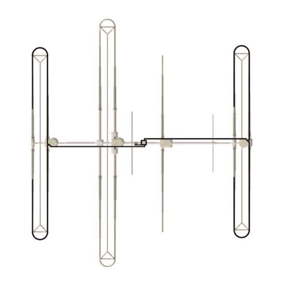
80m Dipole
for the
Dream Beam 36
Assembly Manual
2112 116TH AVE NE SUITE 1-5, BELLEVUE WA, 98004 WWW.STEPPIR.COM TEL: (425)-453-1910 FAX: (425)-462-4415
Advertisement

Related Manuals for SteppIR 80m Dipole


Summary of Contents for SteppIR 80m Dipole
- Page 1 80m Dipole for the Dream Beam 36 Assembly Manual 2112 116TH AVE NE SUITE 1-5, BELLEVUE WA, 98004 WWW.STEPPIR.COM TEL: (425)-453-1910 FAX: (425)-462-4415...
- Page 2 30” 4 conductor control cable 09-0001 Electrical tape 66’ X 3/4” 4 position terminal strip ( only used if Connector Box Option 20-6020-4 was not purchased ) 2112 116TH AVE NE SUITE 1-5, BELLEVUE WA, 98004 WWW.STEPPIR.COM TEL: (425)-453-1910 FAX: (425)-462-4415...
- Page 3 This Option is an add on to the DB 36 and can be installed after or during the buiding process of the DB 36. Some hardware for installing the 80m Dipole will be used from the DB 36. Also with the purchase of the 80m Dipole it includes 2 X 30m/40m truss option. Hardware from both the truss kits and 80m dipole will be needed to complete the assembly.
- Page 4 QTY 2: 5/16” Nylock nut 60-0046 DRIVEN ELEMENT HOUSING QTY 2: 5/16” X 3 1/4” SS hex bolt 60-0075 22 1/4” 80m Dipole Antenna Switch Connector Box Option 2112 116TH AVE NE SUITE 1-5, BELLEVUE WA, 98004 WWW.STEPPIR.COM TEL: (425)-453-1910 FAX: (425)-462-4415...
- Page 5 Also mount the Truss Attachment Plates to the outside of the boom. These will be used to anchor the 80m dipole rope. Use the existing mounting bolts on the EHU/ ERT for securing the Truss attachment Plate...
- Page 6 QTY 1: 30m/40m Truss support 10-1054-01 Hardware from the Bolts form DB 36 truss option assembly QTY 1: Truss Attachment Plate 10-1607-01 Hardware from the truss option 15” 2112 116TH AVE NE SUITE 1-5, BELLEVUE WA, 98004 WWW.STEPPIR.COM TEL: (425)-453-1910 FAX: (425)-462-4415...
- Page 7 3/16” washer that comes with eye bolt Keep plenty of threads to allow for tighting QTY 1: 10-24 Nylock nut Dacron Rope 60-0111 2112 116TH AVE NE SUITE 1-5, BELLEVUE WA, 98004 WWW.STEPPIR.COM TEL: (425)-453-1910 FAX: (425)-462-4415...
- Page 8 3 half hitches and Secure lug to brass cover with electrical tape terminal and weather proof with COAX seal 2112 116TH AVE NE SUITE 1-5, BELLEVUE WA, 98004 WWW.STEPPIR.COM TEL: (425)-453-1910 FAX: (425)-462-4415...
- Page 9 Once the dacron rope has been secured to the Quick Links at the antenna switch finish wrap- ping the 80m dipole conductor around the dacron rope. Wrap the conductor approximately 3 times around the dacron rope per foot. This will prevent any sagging of the conductor.
- Page 10 Reflector side of the dipole will be inserted into the bottom grommet. Refer to Figure 8 for wiring the 80m dipole if you do not have the connector box option. Refer to Figure 9 for wiring the 80m dipole if you have the connector box option.
- Page 11 Figure 8 Wiring Diagram for non connector box instullations Figure 9 Wiring Diagram for connector box instullations 2112 116TH AVE NE SUITE 1-5, BELLEVUE WA, 98004 WWW.STEPPIR.COM TEL: (425)-453-1910 FAX: (425)-462-4415...
- Page 12 Plug the 6 ft COAX jumper from the driven element on the DB 36 to the “OUT” plug on the 80m dipole Antenna Switch. Plug the COAX cable coming up the tower in the “IN” plug on the 80m dipole antenna switch. Refer to Figure 10 for correct installation.
- Page 13 2112 116TH AVE NE SUITE 1-5, BELLEVUE WA, 98004 WWW.STEPPIR.COM TEL: (425)-453-1910 FAX: (425)-462-4415...
- Page 14 2112 116TH AVE NE SUITE 1-5, BELLEVUE WA, 98004 WWW.STEPPIR.COM TEL: (425)-453-1910 FAX: (425)-462-4415...
Need help?
Do you have a question about the 80m Dipole and is the answer not in the manual?
Questions and answers