Table of Contents
Advertisement
Quick Links
DB42 MonstIR PRO Installation Manual
This assembly manual is intended to be
COLOR
printed in full
printed in
black and
portant details could be lost.
SteppIR Antennas 2112 116th Ave NE #1-5, Bellevue, WA 98004 Tel: 425.453.1910 www.steppir.com
Mikhail Mogutuv
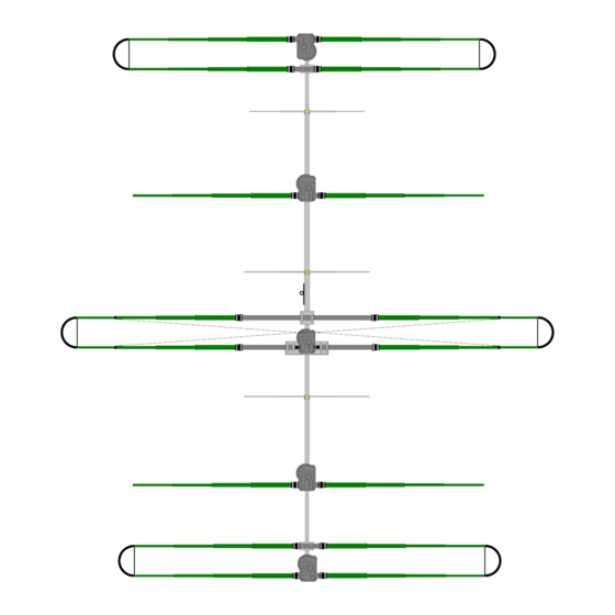
DB42 4 stack
. If the manual is
white, many im-
REV 10.0
02/20/2013
Advertisement
Table of Contents

Related Manuals for SteppIR DB42 MonstIR PRO


Summary of Contents for SteppIR DB42 MonstIR PRO
- Page 1 COLOR printed in full . If the manual is REV 10.0 printed in black and white, many im- 02/20/2013 portant details could be lost. SteppIR Antennas 2112 116th Ave NE #1-5, Bellevue, WA 98004 Tel: 425.453.1910 www.steppir.com...
- Page 2 80M (option) 25.5 23.2 12.4 12.4 10.1 22.0 10.0 23.2 10.8 23.2 10.7 21.9 11.0 25.7 10.6 20.0 11.9 24.1 10.4 12.2 20.0 10.5 11.7 6M w/passive opt. 14.0 25.0 Page 2 Tech Support: www.steppir.com/support Tel: 425.891.6134 support@steppir.com...
-
Page 3: Table Of Contents
Attach the EST’s to the mounting plate SECTION 3.3 Secure the Director 1 EHU to the mounting plate 32—33 SECTION 3.4 Install the CPVC inner-guide tubes 34—35 SECTION 3.5 Return tube assembly—Director 1 36 –38 Page 3 Tech Support: www.steppir.com/support Tel: 425.891.6134 support@steppir.com... - Page 4 Attach the truss mast SECTION 8.3 Attach the truss mast plate to the truss mast SECTION 8.4 Attach the truss boom to the truss mast plate SECTION 8.5 Phillystran truss assembly 55—57 Page 4 Tech Support: www.steppir.com/support Tel: 425.891.6134 support@steppir.com...
- Page 5 Wiring the connector junction box 68—70 Connect the cable from coax switch to the connector junction box SECTION 11.2 Connect the control cable to the dSub splice 72—73 SECTION 11.3 Wiring Test 74—75 Page 5 Tech Support: www.steppir.com/support Tel: 425.891.6134 support@steppir.com...
- Page 6 Mount the DB42 onto the tower mast 91—92 Last steps—read before attaching antenna mast tower mast! CHAPTER SIXTEEN—TROUBLESHOOTING TIPS 93—96 SECTION 16.0 Troubleshooting tips 93—94 Warranty Information SteppIR Contact information Page 6 Tech Support: www.steppir.com/support Tel: 425.891.6134 support@steppir.com...
-
Page 7: Preamble
3. Do a complete inventory of every part, nut and bolt. Yes it takes time, but it also allows you to noti- fy SteppIR if anything is missing and allow time to get it to you before you start assembly of the antenna. -
Page 8: Preamble
OK - - - NOW WHAT? (continued) (Sage advice from Jim Streible, K4DLI—SteppIR Technical Support Guru) 5. Take the controller and power supply out of their wrappings and connect them. The controller does not have to be connected to the antenna in order to familiarize yourself with it. In fact, it is best to get familiar with the controller when it is not connected to the antenna. - Page 9 **If you order the remote driver board option, the ALP board will NOT be mounted inside the SDA 100 controller. In this situation, the ALP board is then part of the remote driver board. Page 9 Tech Support: www.steppir.com/support Tel: 425.891.6134 support@steppir.com...
- Page 10 STONE CHAMFERING TOOL, POLE TIP PREP 09-1022 COAX Seal 10-1029-01 Connector protector packet 10-1510-01 Element Truss Clamp (halves) 72-0030-61 Sweep Hardware Kit 21-7002-01 95' OF 3/16” DACRON ROPE 21-8002 78 FEET OF 2100 PHILLYSTRAN Page 10 Tech Support: www.steppir.com/support Tel: 425.891.6134 support@steppir.com...
- Page 11 1/4”-20 X 3-1/2” SS BOLT 60-0041 1/4” SS WASHER 60-0030 1/4” NYLOK NUT 60-0075 5/16” X 3-1/4” SS BOLT 60-0065 5/16” X 3-1/2” SS BOLT 60-0114 5/16” X 3-3/4” SS BOLT Page 11 Tech Support: www.steppir.com/support Tel: 425.891.6134 support@steppir.com...
- Page 12 2-1/2” X 44” BOOM SECTION 10-1202-81 3” X 72” (.25” WALL) BOOM SECTION 10-1610-23 11-1/2” X 11-1/2” X .25” BOOM TO MAST PLATE 10-1054-02 36” TRUSS SUPPORT FOR D1, 49' LOOP ELEMENT Page 12 Tech Support: www.steppir.com/support Tel: 425.891.6134 support@steppir.com...
- Page 13 ANTI SEIZE PACKET 09-0001 ELECTRICAL TAPE 60-0112 SET SCREW *The parts shown represent a single truss kit. There will be two of these kits, one for each 39 ft end element. Page 13 Tech Support: www.steppir.com/support Tel: 425.891.6134 support@steppir.com...
- Page 14 10-1029-01 CONNECTOR PROTECTOR 60-0117 CABLE CLIP WITH ADHESIVE BACK 60-0112 10-32 X 1/4” SET SCREW With 80m dipole option customer 10-1054-02 36” Element Truss Supports 72-0018-31 39' Element Truss Kit Page 14 Tech Support: www.steppir.com/support Tel: 425.891.6134 support@steppir.com...
- Page 15 You can be assured that the stainless steel fasteners we provide with our products are manufactured of very high quality. Page 15 Tech Support: www.steppir.com/support Tel: 425.891.6134 support@steppir.com...
-
Page 16: Preparing To Build The Db42 Yagi
There is one exception to using the anti-seize - do NOT use the anti-seize compound when connecting the plastic sweeps coupler to the pole ends. This will be covered in more detail later in the manual. Page 16 Tech Support: www.steppir.com/support Tel: 425.891.6134 support@steppir.com... -
Page 17: Element Configuration Drawing
PREAMBLE DB 42 ELEMENT CONFIGURATION DRAWING REVERSE DIRECTION (180 deg) MAST PLATE BOOM FORWARD DIRECTION (Normal) Page 17 Tech Support: www.steppir.com/support Tel: 425.891.6134 support@steppir.com... -
Page 18: Section 1.0 Boom Assembly Overview
1/4” Flat washer 1/4” Flat washer 1/4” Flat washer 5/16” flat washer 1/4” Flat washer 1/4” Flat washer 1/4” Flat washer Note: Check the following page for information on washer placement Page 18 Tech Support: www.steppir.com/support Tel: 425.891.6134 support@steppir.com... - Page 19 1/4” Flat washers FIG. 1.03—EZ Eyebolt configuration Top of boom FIG. 1.04 QTY 1: 60-0151 No washers are required 3/8”x4-1/2” for the eyebolt Stainless Eyebolt QTY 1: 60-0050 3/8” Nylock nut Page 19 Tech Support: www.steppir.com/support Tel: 425.891.6134 support@steppir.com...
-
Page 20: Section 1.1 Measuring And Marking The Boom
Boom truss bracket Remainder of boom 20.75” 0.75” 30.75” 70.125” 84.75” FIG. 1.11 Long side of boom Short side of boom EZ Eyebolt is NOT at the center of the boom Page 20 Tech Support: www.steppir.com/support Tel: 425.891.6134 support@steppir.com... -
Page 21: Boom Marking Table
Boom truss clamp 474.75 inch (474-3/4”) 1205.87 cm Director 3 return 494.75 inch (494-3/4”) 1256.66 cm 39 ft Truss support / 80m Dipole Support 497.75 inch (497-3/4”) 1264.29 cm Director 3 Page 21 Tech Support: www.steppir.com/support Tel: 425.891.6134 support@steppir.com... -
Page 22: Section 2.0 Center-To-Center Spacing Measurements
MOUNTING THE EHU’S ON THE BOOM SECTION 2.0 CENTER-TO-CENTER SPACING MEASUREMENTS It is critically important that the center-to-center spacing is correct when assembling your SteppIR Ya- gi. Use figure 2.01 for placement of each of the elements. Start from the left edge of the boom and measure from there. -
Page 23: Element Housing Unit (Ehu) Wiring Overview
TROLLER IS CONNECTED TO THE CONTROL CABLE. Even if the power is turned off of the con- troller, damage can occur. This is the number one cause of antenna installation failures, so please be sure to heed the advice. Figure 2.10 gives an overview of the inside of a SteppIR EHU. FIG. 2.10 Element support tube... - Page 24 6 Pin Header Wiring Sequence 4 Pin Header Wiring Sequence (EHU’s with Relays) (EHU’s without Relays) BLACK GREEN WHITE BLUE BROWN BLACK GREEN WHITE TERMINAL PLUG FIG. 2.14 TERMINAL HEADER Page 24 Tech Support: www.steppir.com/support Tel: 425.891.6134 support@steppir.com...
- Page 25 Repeat wiring and coax seal preparation for each EHU. When finished, the EHU’s will be secured to the aluminum element mounting plates. This is covered in detail in the next chapter. FIG. 2.17 FIG. 2.15 FIG. 2.16 FIG. 2.18 FIG. 2.19 Page 25 Tech Support: www.steppir.com/support Tel: 425.891.6134 support@steppir.com...
- Page 26 5/16” x 5” Hex head bolt 10-1608-01 Element return plate 70-2029-01 1-3/4” X 60-3/4” EST tube 10-1601-61 3” Aluminum saddle half 70-2028-01 1-3/4” x 66-3/8” EST tube 10-1606-01 2-1/4” x 0.125” Reinforcement plate Page 26 Tech Support: www.steppir.com/support Tel: 425.891.6134 support@steppir.com...
- Page 27 49 feet in length too. This is the he ba- sis for one of the SteppIR patents and is fundamental in the outstanding performance the DB42 delivers on the 40m and 30m bands while being 40% shorter than a full sized Yagi on those bands.
- Page 28 FIG. 3.04 FIG. 3.03 FIG. 3.05 REFLECTOR DIRECTOR FIG. 3.06 FIG. 3.08 FIG. 3.07 FIG. 3.09 FIG. 3.10 Page 28 Tech Support: www.steppir.com/support Tel: 425.891.6134 support@steppir.com...
- Page 29 2” Aluminum saddle half 10-1601-11 2” x 3” Reinforcing tube 70-2029-01 1-3/4” x 60-3/4” EST tube 60-0066 5/16” x 4” Hex head bolt 60-0141 5/16” x 5” Hex head bolt Page 29 Tech Support: www.steppir.com/support Tel: 425.891.6134 support@steppir.com...
- Page 30 PREPARE MOUNTING PLATE FOR ATTACHING THE EST’s All of the SteppIR EHU’s have a “diverter” inside them to direct each half of the copper-beryllium strip in the correct direction. The Driven element on the DB42 is quite a bit longer than the normal loops, so a different diverter system must be employed.
- Page 31 EST’s ready for the EHU to be mounted. FIG. 3.22 FIG. 3.20 FIG. 3.23 FIG. 3.21 FIG. 3.27 FIG. 3.26 FIG. 3.25 FIG. 3.24 FLUSH w/ END CENTERED ON SADDLE Page 31 Tech Support: www.steppir.com/support Tel: 425.891.6134 support@steppir.com...
-
Page 32: Secure The Director 1 Ehu To The Mounting Plate
#10 Nylock nut 60-0018 #10 Flat washer 10-1502-12 EHU gasket 10-1022-21 EHU lid 60-0017 #10 x 3/4” machine screw 60-0017-10 #10 x 3/4” Flat head screw FIG. 3.30 70-3409-01 Director 1 EHU Page 32 Tech Support: www.steppir.com/support Tel: 425.891.6134 support@steppir.com... -
Page 33: Secure The Director 1 Ehu To The Mounting Plate
ON THE MOUNTNG PLATE FIG. 3.35 Key QTY Part # Description 60-0101 #10 x 3/4” Machine screw with locking strip on threads (see PIC XX) 60-0018 #10 Flat washer 10-1613-11 1/4” Aluminum spacer Page 33 Tech Support: www.steppir.com/support Tel: 425.891.6134 support@steppir.com... - Page 34 FIG. 3.40 GLUE GOES HERE FIG. 3.44 FIG. 3.41 FIG. 3.42 FIG. 3.43 FIG. 3.45 Driven Element EST— Inner guide tube assembly (Drawing is shown as a cut-away for visual purposes) Page 34 Tech Support: www.steppir.com/support Tel: 425.891.6134 support@steppir.com...
- Page 35 CPVC inner guide tubes will extend when glued together. This is why we recommend you wait until much later in the process to complete the guide tube assembly. FIG. 3.46 FIG. 3.47 FIG. 3.48 FIG. 3.49 FIG. 3.50 Page 35 Tech Support: www.steppir.com/support Tel: 425.891.6134 support@steppir.com...
- Page 36 5/16” Nylock nut 10-1601-22 2” Aluminum saddle half 10-1601-41 2-1/2” Aluminum saddle half 10-1630-21 2” x 12” Stress relief sleeve 70-2028-01 1-3/4” x 66-3/8” EST return tube 10-1608-01 Element return plate Page 36 Tech Support: www.steppir.com/support Tel: 425.891.6134 support@steppir.com...
- Page 37 Do not forget to use anti-seize on all stainless steel fasteners, and also re- member to install a set screw into each saddle pair (one set screw per saddle pair). FIG. 3.52 FIG. 3.53 FIG. 3.54 FIG. 3.57 FIG. 3.55 FIG. 3.56 Page 37 Tech Support: www.steppir.com/support Tel: 425.891.6134 support@steppir.com...
- Page 38 3.64. This will stabilize the boom as you continue with construction of the antenna. FIG. 3.59 FIG. 3.60 FIG. 3.61 FIG. 3.58 FIG. 3.63 FIG. 3.62 FIG. 3.64 Page 38 Tech Support: www.steppir.com/support Tel: 425.891.6134 support@steppir.com...
- Page 39 D (x8) C (x10) E (x8) WARNING! Extra bracket used in this section if installing the 80m dipole. Refer to the 80m dipole instruc- FIG. 4.01 tions for further detail. Page 39 Tech Support: www.steppir.com/support Tel: 425.891.6134 support@steppir.com...
-
Page 40: Secure Mounting Plate And Ehu To Boom—Reflector
EHU housing. Measure the proper distance from the edge of the boom to the center point of the element (5.0 inches) as (A tip from Adam Blackmer K7EDX, SteppIR operations manager— use the mold spline shown in figure 4.06. - Page 41 (one set screw per saddle pair). Figure 4.15 shows the completed director EHU and return bracket. FIG. 4.12 FIG. 4.11 FIG. 4.10 FIG. 4.13 FIG. 4.14 FIG. 4.15 Page 41 Tech Support: www.steppir.com/support Tel: 425.891.6134 support@steppir.com...
-
Page 42: Section 5.0 Driven Element Assembly Drawing
#10 Nylock nut 60-0065 5/16”x3-1/2” Hex head bolt C (x10) 60-0046 5/16” Nylock nut 70-3412-01 Driven Element EHU 10-1502-01 Element housing gasket 10-1015-11 Element mounting plate 10-1601-22 2” Aluminum saddle half Page 42 Tech Support: www.steppir.com/support Tel: 425.891.6134 support@steppir.com... - Page 43 EHU housing. Measure the proper distance (116 inches) from the center-point of the Driven element to the center-point of (A tip from Adam Blackmer K7EDX, SteppIR operations manager— use the mold the Director 1 element.
-
Page 44: Director 2 Ehu Assembly Drawing
#10 Nylock nut 60-0114 5/16”x3-3/4” Hex head bolt 60-0046 5/16” Nylock nut 70-3408-01 Director 2 EHU C (x10) 10-1502-01 Element housing gasket 70-2030-11 Element mounting plate 10-1601-32 2-1/4” Aluminum saddle half Page 44 Tech Support: www.steppir.com/support Tel: 425.891.6134 support@steppir.com... - Page 45 EHU housing. Measure the proper distance (150 inches) from the center-point of the Driven element to the center-point of (A tip from Adam Blackmer K7EDX, SteppIR operations manager— use the mold the Director 1 element.
- Page 46 10-1015-11 EST Return tube this section if installing the 80m dipole. Refer to 60-0114 5/16” x 3-3/4” Hex head bolt the 80m dipole instruc- Boom counterweight tions for further detail. Page 46 Tech Support: www.steppir.com/support Tel: 425.891.6134 support@steppir.com...
- Page 47 Level the EHU as shown in figure 7.09 and tighten the aluminum saddles firmly. FIG. 7.02 FIG. 7.03 FIG. 7.04 FIG. 7.05 FIG. 7.06 FIG. 7.08 FIG. 7.09 FIG. 7.07 Page 47 Tech Support: www.steppir.com/support Tel: 425.891.6134 support@steppir.com...
-
Page 48: Section 7.1 Return Tube Assembly—Director 3
Figure 7.18 shows the completed Director 3 EHU and return assembly. FIG. 7.13 FIG. 7.12 FIG. 7.10 FIG. 7.11 FIG. 7.14 FIG. 7.15 FIG. 7.17 FIG. 7.16 FIG. 7.18 Page 48 Tech Support: www.steppir.com/support Tel: 425.891.6134 support@steppir.com... -
Page 49: Section 8.0
60-0145 3/8” Stainless steel eyebolt 60-0141 5/16” x 5” Hex head bolt 60-0046 5/16” Nylock nut 60-0050 3/8” Nylock nut 10-1601-61 3” Aluminum saddle half 10-1610-22 11-1/2” Aluminum mast plate Page 49 Tech Support: www.steppir.com/support Tel: 425.891.6134 support@steppir.com... -
Page 50: Section 8.0
EZ-Eye. Position the mast plate to the boom, sliding the 5” threaded bolt through the eyebolt as shown in figure 8.09. FIG. 8.04 FIG. 8.02 FIG. 8.03 FIG. 8.06 FIG. 8.07 FIG. 8.05 FIG. 8.08 FIG. 8.09 Page 50 Tech Support: www.steppir.com/support Tel: 425.891.6134 support@steppir.com... -
Page 51: Secure The Mast Plate To The Boom
Only the exposed half of the saddles will require a set screw. Figure 8.15 shows the completed mast plate assembly. FIG. 8.10 FIG. 8.12 FIG. 8.11 FIG. 8.15 FIG. 8.14 FIG. 8.13 Page 51 Tech Support: www.steppir.com/support Tel: 425.891.6134 support@steppir.com... -
Page 52: Attach The Truss Mast
Part # Description 10-1618-41 48” Boom truss support mast FIG. 8.25 60-0115 5/16” x 4-1/2” Hex head bolt 10-1601-03 1-3/4” Aluminum saddle half 10-1613-11 1/4” aluminum spacer 60-0046 5/16” Nylock nut Page 52 Tech Support: www.steppir.com/support Tel: 425.891.6134 support@steppir.com... -
Page 53: Attach The Truss Mast Plate To The Truss Mast
Be sure to install the set screws and tighten them as shown in figure 8.33. FIG. 8.32 FIG. 8.30 FIG. 8.31 FIG. 8.33 ANTENNA MAST GOES HERE Page 53 Tech Support: www.steppir.com/support Tel: 425.891.6134 support@steppir.com... -
Page 54: Attach The Truss Boom To The Truss Mast Plate
Tighten firmly. Install and tighten the set screws. Figure 8.43 figure 8.44 shows the completed truss mast plate assembly. FIG. 8.40 FIG. 8.41 FIG. 8.42 FIG. 8.43 FIG. 8.44 Page 54 Tech Support: www.steppir.com/support Tel: 425.891.6134 support@steppir.com... -
Page 55: Phillystran Truss Assembly
FIG. 8.52 QTY 1: 60-0152 QTY 2: 60-0144 3/8” x 1.75” 7/16” Galvanized Hex head bolt washer FIG. 8.53 QTY 1: 60-0050 3/8” Nylock nut QTY 2: 60-0070 6” Galvanized turnbuckle Page 55 Tech Support: www.steppir.com/support Tel: 425.891.6134 support@steppir.com... -
Page 56: Phillystran Truss Assembly
(or your fingers). Secure the Phillystran pieces at the end of the wire clips with electrical tape as shown in figure 8.55. FIG. 8.53 FIG. 8.51 FIG. 8.52 FIG. 8.54 FIG. 8.55 Page 56 Tech Support: www.steppir.com/support Tel: 425.891.6134 support@steppir.com... - Page 57 When the thimble is attached, be sure to bend the ends back so that it cannot fall off, as shown in figure 8.60. FIG. 8.58 FIG. 8.56 FIG. 8.56 FIG. 8.60 FIG. 8.59 Page 57 Tech Support: www.steppir.com/support Tel: 425.891.6134 support@steppir.com...
-
Page 58: Double Truss Overview Drawing
5/16” x 3.5” Hex head bolt 60-0046 5/16” Nylock nut 2 (x 2) 60-0083 6” Galvanized turnbuckle 4 (x 2) 60-0044 Phillystran end cap 78 ft 21-8002 Phillystran 2100I (trim as you go) Page 58 Tech Support: www.steppir.com/support Tel: 425.891.6134 support@steppir.com... -
Page 59: Phillystran Double Truss Installation
3 portions of the boom truss. When all of the Phillystran is secured, the boom can be leveled. FIG. 8.63 FIG. 8.62 FIG. 8.61 FIG. 8.64 FIG. 8.65 FIG. 8.66 Page 59 Tech Support: www.steppir.com/support Tel: 425.891.6134 support@steppir.com... -
Page 60: Phillystran Double Truss Installation
8.69. Secure with electrical tape. Figure 8.70 figure 8.71 show the completed Phillystran truss ends. FIG. 8.69 FIG. 8.68 FIG. 8.67 FIG. 8.71 FIG. 8.70 Page 60 Tech Support: www.steppir.com/support Tel: 425.891.6134 support@steppir.com... - Page 61 Passive Element reach total length element length (per side) 110.5 inch 26.25 inch (26-1/4”) 108.25 inch 25.125 inch (25-1/4”) 106.125 inch 24.06 inch (24-1/16”) FIG. 9.02 FIG. 9.03 FIG. 9.04 Page 61 Tech Support: www.steppir.com/support Tel: 425.891.6134 support@steppir.com...
- Page 62 EHU to 6m passive 117.5 inches 2 inch 5/16 x 3.25 inch 275.0 inches 3 inch 5/16 x 4.5 inch 432.0 inches 2 inch 5/16 x 3.25 inch Page 62 Tech Support: www.steppir.com/support Tel: 425.891.6134 support@steppir.com...
-
Page 63: Mounting The Coax Switch Housing
It is not required, but you may want to tin the ends of the control cable, to prevent fraying of the copper strands. FIG. 10.01 FIG. 10.02 FIG. 10.03 FIG. 10.04 FIG. 10.05 FIG. 10.06 FIG. 10.07 Page 63 Tech Support: www.steppir.com/support Tel: 425.891.6134 support@steppir.com... -
Page 64: Coax Switch Wiring
Additionally, a tie wrap works well. FIG. 10.10 FIG. 10.11 SHIELD BLACK DO NOT USE WHITE FIG. 10.12 FIG. 10.13 Page 64 Tech Support: www.steppir.com/support Tel: 425.891.6134 support@steppir.com... -
Page 65: Sealing And Securing The Coax Switch Housing
You will likely need to take the lid off for the final wiring test, but leaving it in place is necessary in or- der to protect the components of the coax switch housing while completing assembly of the antenna. FIG. 10.21 FIG. 10.20 FIG. 10.22 FIG. 10.23 FIG. 10.24 FIG. 10.25 Page 65 Tech Support: www.steppir.com/support Tel: 425.891.6134 support@steppir.com... -
Page 66: Attach The Coax Jumpers And Feed Line
Coax IN (if no 80m dipole DIR2 DIR1 OUT 2: 11 ft 6 inch (PN 21-6301-96) OUT 3: 8 ft (PN 21-6301-80) OUT 1: 15 ft Coax Jumper (PN 21-6301-98) Page 66 Tech Support: www.steppir.com/support Tel: 425.891.6134 support@steppir.com... -
Page 67: Wiring The Connector Junction Box
11.04. The hinged cover needs to open from the bottom, as shown figure 11.05. Figure 11.06 shows the connector junction box mounted on the mast plate. FIG. 11.01 FIG. 11.02 FIG. 11.03 FIG. 11.04 FIG. 11.05 FIG. 11.06 Page 67 Tech Support: www.steppir.com/support Tel: 425.891.6134 support@steppir.com... -
Page 68: Wiring The Connector Junction Box
Pin 25 is NOT USED. COAX SWITCH 4 wire control cable; the green wire needs to be trimmed and taped; HOUSING R1 is NOT USED. 3 total wires used, plus shield wire. Page 68 Tech Support: www.steppir.com/support Tel: 425.891.6134 support@steppir.com... -
Page 69: Section 11.1
1 2 3 4 5 6 7 8 9 10 11 12 13 14 P2 Plug 15 16 17 18 19 20 21 22 23 24 25 Not used CUTOUT CUTOUT CUTOUT 4 wire control cable key 6 wire control cable key Page 69 Tech Support: www.steppir.com/support Tel: 425.891.6134 support@steppir.com... -
Page 70: Section 11.1
WHITE / BLACK-RED RED / BLACK-WHITE BLACK / WHITE-RED WHITE / RED STRIPE RED / BLACK STRIPE RED / GREEN STRIPE NOT USED! Page 70 Tech Support: www.steppir.com/support Tel: 425.891.6134 support@steppir.com... - Page 71 LOCATED INSIDE PN 70-2038 LOCATED INSIDE PN 70-3002-01 CONNECTOR JUNCTION BOX 80M DIPOLE ANTENNA SWITCH HOUSING Shield Black FACTORY INSTALLED JUMPER Green Page 71 Tech Support: www.steppir.com/support Tel: 425.891.6134 support@steppir.com...
- Page 72 CONNECTING CONTROL CABLE TO dSUB FIELD SPLICE The DB25 control cable splice allows for much more convenient connection of control cable to the SteppIR controller. By utilizing this connector splice, there is no need to cut the DB25 connector off and re-solder when running cable through conduit.
- Page 73 WHITE / RED STRIPE RED / BLACK STRIPE RED / GREEN STRIPE NOT USED! GND (SHIELD GOES HERE) GND (SHIELD CAN GO HERE TO0) Page 73 Tech Support: www.steppir.com/support Tel: 425.891.6134 support@steppir.com...
-
Page 74: Wiring Test
The Driven EHU will show a short between the coax connector center pin and the copper tape and D2 will show an open circuit from the coax connector to the copper tape. Page 74 Tech Support: www.steppir.com/support Tel: 425.891.6134 support@steppir.com... -
Page 75: Wiring Test
Remove control cable and then set controller to 6m. Wait for tuning to stop and the plug the control cable back in and hit the retract button. The antenna will now be retracted and ready to be installed. Page 75 Tech Support: www.steppir.com/support Tel: 425.891.6134 support@steppir.com... - Page 76 THIS PAGE INTENTIONALLY LEFT BLANK Page 76 Tech Support: www.steppir.com/support Tel: 425.891.6134 support@steppir.com...
- Page 77 Each line needs to change in color to ensure even adhesion temperatures . FIG. 12.01 TRIM THE TIP OF EACH POLE FOR AN OVERALL LENGTH OF 212.75 INCHES FIG. 12.03 FIG. 12.02 FIG. 12.04 FIG. 12.06 FIG. 12.05 FIG. 12.07 Page 77 Tech Support: www.steppir.com/support Tel: 425.891.6134 support@steppir.com...
- Page 78 Be sure there is no overlap of the grip tape – it should be fine from the factory but the OD of poles var- ies slightly, so if there is overlap, make sure you trim the tape so there is a gap, as shown in figure 12.08, Step FIG. 10.08 FIG. 12.08 Page 78 Tech Support: www.steppir.com/support Tel: 425.891.6134 support@steppir.com...
- Page 79 These screws will be completely tightened later, tightening to this point provides a framework for the ensuing steps. FIG. 12.10 FIG. 12.11 Figure 1.07 FIG. 12.12 0.25” GAP Page 79 Tech Support: www.steppir.com/support Tel: 425.891.6134 support@steppir.com...
- Page 80 When completely tightened, the sweep couplers should have just a slight gap, as shown in figure 12.16. FIG. 12.14 FIG. 12.15 FIG. 12.13 FIG. 12.16 FIG. 12.17 FIG. 12.18 Page 80 Tech Support: www.steppir.com/support Tel: 425.891.6134 support@steppir.com...
-
Page 81: Mount The Fiberglass Spreaders On The Sweep Couplers
Tighten the Nylock nuts firmly. Be sure to use anti-seize on these screws or they very likely will gall and have to be replaced. Repeat the above steps for the remaining sweeps. Figure 12.23 shows the completed sweep assembly. FIG. 12.21 FIG. 12.22 FIG. 12.20 FIG. 12.23 Page 81 Tech Support: www.steppir.com/support Tel: 425.891.6134 support@steppir.com... - Page 82 12.32. Be sure that the plas- tic housing bottoms out on the pole tip, as shown in figure 12.33. Repeat for the other non-loop telescoping pole tips. FIG. 12.30 FIG. 12.31 FIG. 12.32 FIG. 12.33 Page 82 Tech Support: www.steppir.com/support Tel: 425.891.6134 support@steppir.com...
-
Page 83: Chapter Thirteen
GLUE ends of the 39-7/8” pipe GLUE FIG. 13.04 FIG. 13.03 FIG. 13.02 3/4” FIG. 13.06 FIG. 13.07 FIG. 13.05 Page 83 Tech Support: www.steppir.com/support Tel: 425.891.6134 support@steppir.com... -
Page 84: Chapter Thirteen
Quick disconnect boot locking ring (these are molded into the base section of each telescoping pole and are used to keep the pole from sliding out of the quick disconnect boots in high wind situations) Page 84 Tech Support: www.steppir.com/support Tel: 425.891.6134 support@steppir.com... -
Page 85: Section 13.1
Reflector element. Repeat the above steps for Director 2. The instructions are exactly the same with the exception of the orientation of the EHU and return tube. FIG. 13.11 FIG. 13.12 FIG. 13.13 FIG. 13.14 FIG. 13.16 FIG. 13.15 FIG. 13.18 FIG. 13.17 Page 85 Tech Support: www.steppir.com/support Tel: 425.891.6134 support@steppir.com... -
Page 86: Section 14.0 Installing The Truss Support Mast
14.05. The stainless steel washers are both positioned between the eye of the outside turnbuckle and the Nylock nut as shown in figure 14.06. FIG. 14.01 FIG. 14.02 FIG. 14.03 FIG. 14.04 FIG. 14.05 FIG. 14.06 Page 86 Tech Support: www.steppir.com/support Tel: 425.891.6134 support@steppir.com... -
Page 87: Section 14.1 Attach The Truss Couplers
Dacron rope is secured to the truss line as shown in figure 14.18. FIG. 14.12 FIG. 14.10 FIG. 14.11 FIG. 14.13 FIG. 14.14 FIG. 14.15 Dacron Rope FIG. 14.18 FIG. 14.17 FIG. 14.16 Page 87 Tech Support: www.steppir.com/support Tel: 425.891.6134 support@steppir.com... -
Page 88: Routing The Dacron Truss Cord
“stacked” one on top of the other as shown in figure 14.25. Tighten the wire clips firmly. FIG. 14.20 FIG. 14.22 FIG. 14.21 FIG. 14.23 FIG. 14.25 FIG. 14.24 Page 88 Tech Support: www.steppir.com/support Tel: 425.891.6134 support@steppir.com... -
Page 89: Routing The Dacron Truss Cord
When the position of the loops are as desired, tighten the quick disconnect boots firmly. Wait 30 minutes and tighten again. FIG. 14.26 FIG. 14.27 FIG. 14.28 FIG. 14.29 FIG. 14.31 FIG. 14.30 Page 89 Tech Support: www.steppir.com/support Tel: 425.891.6134 support@steppir.com... -
Page 90: Secure The Cables Onto The Boom
FIG. 15.03 FIG. 15.02 FIG. 15.01 Page 90 Tech Support: www.steppir.com/support Tel: 425.891.6134 support@steppir.com... -
Page 91: Mount The Db42 Onto The Tower Mast
15.10. In most cases the tower mast is 2 inches in diameter, but occasionally the mast size may be different, depending on the customers situation. SteppIR offers saddle sizes in 1-3/4”, 2”, 2-1/4”, 2- 1/2” and 3”. Since the vast majority of installations of the DB42 will be utilizing the standard 2 inch saddles, that is the verbiage used in the instructions that follow. - Page 92 11. Check to be sure that the elements are level with the boom— a level antenna looks much better when suspended in the air than one that is not! 12. Get the DB42 Yagi on that tower so you can work some good DX! Page 92 Tech Support: www.steppir.com/support Tel: 425.891.6134 support@steppir.com...
- Page 93 SECTION 16.0 TROUBLESHOOTING TIPS SteppIR antennas are all powered by stepper motors, hence the name. Stepper motors function by rotating the shaft a specific number of “steps” per revolution. The SDA 100 is simply counting the steps, of which for each step sequence there is a known length that the antenna is adjusting. If for some reason the anten- na gets out of calibration, the method for recalibrating is pretty simple.
- Page 94 Again, be careful NOT to short the pins. Even if the controller is turned off, there is always voltage going to the pins with a SteppIR controller. We do this to “lock” the step- per motors, and minimize the need to calibrate the antenna on a regular basis.
- Page 95 SteppIR will pay for standard shipping back to the buyer. The manufacturer assumes no further liability beyond repair or replace- ment of the product.
-
Page 96: Steppir Contact Information
SteppIR Contact Information Email : New orders or questions about your current order: sales@steppir.com Existing customers requiring technical or product support services: support@steppir.com Information and questions about our products: sales@steppir.com Phone / Fax: Phone: 425-453-1910—9:30am to 4:30pm Pacific Standard Time Fax : 425-462-4415 Tech Support: 425-891-6134—10:00am to 5:00pm Eastern Standard Time... - Page 97 Page 97 Tech Support: www.steppir.com/support Tel: 425.891.6134 support@steppir.com...
- Page 98 Page 98 2112 116th Ave NE #1-5, Bellevue, WA 98004 Tel: 425.453.1910 email: sales@steppir.com Tech Support: www.steppir.com/support Tel: 425.891.6134 support@steppir.com...
Need help?
Do you have a question about the DB42 MonstIR PRO and is the answer not in the manual?
Questions and answers