Table of Contents
Advertisement
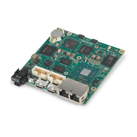
HARDWARE INSTALLATION MANUAL
CompactRIO Single-Board
Controller with NI-DAQmx
Use this document to do the following:
•
Design mounting and installation solutions for the CompactRIO Single-Board Controller
with DAQmx
•
Ground the single-board controller
•
Connect the single-board controller to power and to a host computer
•
Manage and design thermal solutions for the single-board controller
Note
For information about designing systems and fixtures using the single-board
controller, programming and configuring the single-board controller, and designing a
RIO mezzanine card connector, refer to the CompactRIO Single-Board Controller
with DAQmx System Development Manual on ni.com/manuals.
Table 1. CompactRIO Single Board Controller with NI-DAQmx Models
Digital I/O Models
sbRIO-9603
sbRIO-9608
sbRIO-9609
Contents
CompactRIO Single-Board Controller Concepts......................................................................2
Block Diagrams.........................................................................................................................4
Multifunction I/O Models
sbRIO-9628
sbRIO-9629
sbRIO-9638
Advertisement
Table of Contents

Related Manuals for National Instruments CompactRIO sbRIO-9603


Summary of Contents for National Instruments CompactRIO sbRIO-9603
- Page 1 HARDWARE INSTALLATION MANUAL CompactRIO Single-Board Controller with NI-DAQmx Use this document to do the following: • Design mounting and installation solutions for the CompactRIO Single-Board Controller with DAQmx • Ground the single-board controller • Connect the single-board controller to power and to a host computer •...
-
Page 2: Table Of Contents
sbRIO-96xx Features......................10 Ports and Connectors...................... 10 RESET Button.........................22 LEDs..........................24 Internal Real-Time Clock (RTC)..................26 Real-Time Clock (RTC) Battery..................26 Mounting a sbRIO-960x Model....................27 sbRIO-960x Dimensions....................28 sbRIO-960x Mounting Direction Options..............32 Mounting a sbRIO-962x/sbRIO-963x Model................. 34 sbRIO-962x/sbRIO-963x Dimensions................35 sbRIO-962x/sbRIO-963x Mounting Direction Options.......... - Page 3 Onboard I/O Module refers to the distinct onboard modules designed into the sbRIO-96xx. sbRIO I/O Module In this document, sbRIO I/O Module refers to both onboard I/O and C Series modules. CompactRIO Single-Board Controller with NI-DAQmx Hardware Installation Manual | © National Instruments | 3...
- Page 4 Block Diagrams Figure 1. sbRIO-9603 Block Diagram sbRIO-9603 RS-232 UART RS-232 1 GB XCVR Console Out DDR3L RJ-45 TSN Gigabit 4 GB Intel Atom E3805 Ethernet Port eMMC Disk Dual-Core RJ-45 TSN Gigabit 1.33 GHz Processor Watchdog Ethernet Port USB 2.0 Device Temperature Type-C Connector Sensors...
- Page 5 NI-DAQmx Technology Processor Data Path LabVIEW FPGA API Data Path NI-DAQmx API Data Path 9-30 VDC Power Path On-board Power Input Power Selection and Supplies Protection CompactRIO Single-Board Controller with NI-DAQmx Hardware Installation Manual | © National Instruments | 5...
- Page 6 Figure 3. sbRIO-9609 Block Diagram sbRIO-9609 2 GB DDR3L 4 GB eMMC Disk RS-232 UART RS-232 XCVR Console Out Watchdog RJ-45 TSN Gigabit Temperature Intel Atom E3845 Ethernet Port Sensors Quad-Core 1.91 GHz Processor RJ-45 TSN Gigabit Ethernet Port USB 2.0 Device Battery Holder Type-C Connector (BR1632)
- Page 7 16x Multiplexed Analog Input Optional System Power 9-30 VDC 4x Analog NI-DAQmx NI-DAQmx Output Technology Technology 9-30 VDC On-board Power Input Power Selection and Supplies Protection CompactRIO Single-Board Controller with NI-DAQmx Hardware Installation Manual | © National Instruments | 7...
- Page 8 Figure 5. sbRIO-9629 Block Diagram sbRIO-9629 RS-232 UART 2 GB RS-232 XCVR DDR3L RS-232 UART 4 GB RS-232 XCVR eMMC Disk Console Out RS-485 UART XCVR Watchdog RS-485 Processor Data Path LabVIEW FPGA API Data Path Temperature RJ-45 TSN Gigabit Intel Atom E3845 Sensors NI-DAQmx API Data Path...
- Page 9 Configurable per Module 4x Digital I/O (5 V Tolerant) 16x Multiplexed Analog Input 4x Analog On-board Power 9-30 VDC Input NI-DAQmx Output Power Selection and Technology Supplies Protection CompactRIO Single-Board Controller with NI-DAQmx Hardware Installation Manual | © National Instruments | 9...
-
Page 10: Sbrio-96Xx Features
sbRIO-96xx Features Ports and Connectors Figure 7. sbRIO-960x Ports and Connectors 1. Power terminal 5. RS-232 serial port with Console Out (ASRL1) 2. CAN port 6. RJ-45 Gigabit Ethernet ports 3. USB Type-C 2.0 device port 7. RMC connector 4. USB Type-C 3.1 host port (with DisplayPort on the sbRIO-9609) 10 | ni.com | CompactRIO Single-Board Controller with NI-DAQmx Hardware Installation Manual... - Page 11 Samtec SEAM connectors come in multiple heights, indicated in millimeters by the XX.X portion of the SEAM-40- -S-06-2 example part number. You can order a mating XX.X CompactRIO Single-Board Controller with NI-DAQmx Hardware Installation Manual | © National Instruments | 11...
- Page 12 connector for the RMC connector from Samtec, the connector manufacturer, or from a distributor such as Arrow or Avnet. The height of the mating connector you select to mate to the RMC connector determines the height of the standoffs you need. Samtec requires that standoffs be 0.15 mm (0.006 in.) taller than the combined height of the RMC and mating connectors.
- Page 13 AGND AGND AGND AGND AGND AGND AGND AGND DGND DIO0 DGND DIO1 DGND DIO2 DGND DIO3 Connector1 (DIO Port) Use Connector1 port for digital input/output configurations. CompactRIO Single-Board Controller with NI-DAQmx Hardware Installation Manual | © National Instruments | 13...
- Page 14 Figure 10. Connector1 Pinout DGND DIO4 DGND DIO5 DGND DIO6 DGND DIO7 DGND DIO8 DGND DIO9 DGND DIO10 DGND DIO11 DGND DIO12 DGND DIO13 DGND DIO14 DGND DIO15 DGND DIO16 DGND DIO17 DGND DIO18 DGND DIO19 DGND DIO20 DGND DIO21 DGND DIO22 DGND...
- Page 15 Console Out startup option is enabled. Figure 12. RS-232 Serial Port Pinout Shield Table 6. RS-232 Serial Port Accessories Accessory Part Number NI Single-Board RIO 10-pin header to 9-pin D-SUB 153158-10 CompactRIO Single-Board Controller with NI-DAQmx Hardware Installation Manual | © National Instruments | 15...
- Page 16 RS-485 Serial Port The RS-485 serial port implements a shrouded header, 10-position modular jack to connect displays or input devices. Use Serial VIs to read from and write to the serial port. Refer to the LabVIEW Help for information about the Serial VIs. Find examples on how to use NI-Serial or NI-VISA to perform serial communication in the NI Example Finder.
- Page 17 RIO Mezzanine Card Connector Figure 14. sbRIO-960x RMC Connector Location and Dimensions 98.4 mm (3.87 in.) 96.7 mm (3.81 in.) 0.0 mm (0.00 in.) CompactRIO Single-Board Controller with NI-DAQmx Hardware Installation Manual | © National Instruments | 17...
- Page 18 Figure 15. sbRIO-962x/sbRIO-963x RMC Connector Location and Dimensions 98.4 mm (3.87 in.) 96.7 mm (3.81 in.) 0.0 mm (0.00 in.) Caution RMCs are not hot-swappable. Disconnect power before mating or unmating. 18 | ni.com | CompactRIO Single-Board Controller with NI-DAQmx Hardware Installation Manual...
- Page 19 Use the RMC Connector Feature Set Compatibility table to determine if a previously designed RMC is compatible with the new RMC pinout and as guidance on how to design an RMC for compatibility with future generations of the RMC. CompactRIO Single-Board Controller with NI-DAQmx Hardware Installation Manual | © National Instruments | 19...
- Page 20 Table 8. RMC Connector Feature Set Compatibility sbRIO-96xx (CompactRIO sbRIO-96x7 Single-Board (Previous Controllers with NI- Future Design Feature Set Generation) DAQmx) Compatibility DIO[0..63] DIO[64..95] Not guaranteed FPGA_CONF USB_D+/- RST# SYS_RST# 3.3V FPGA_VIO VBAT Not guaranteed RS-232 Not guaranteed Processor I/O via Visit ni.com/r/sbrio DIO[0..95]...
- Page 21 USB-to-IDE adapters, keyboards, mice, and USB cameras. Note To use DisplayPort Alt Mode and USB at the same time, use an appropriate adapter that breaks out into both ports. CompactRIO Single-Board Controller with NI-DAQmx Hardware Installation Manual | © National Instruments | 21...
-
Page 22: Reset Button
Table 11. NI USB Type-C Adapters for sbRIO-96xx Adapter Length Part Number USB to DVI Adapter with Retention, USB Type-C Male to DVI-D 0.5 m 143558-0R5 Female USB to VGA Adapter with Retention, USB Type-C Male to VGA 0.5 m 143557-0R5 Female USB Cable with Retention, Type-C Male to Type-A Female, USB... - Page 23 Press and hold RESET button for < 5 s • Network settings reset Safe Mode • RT Startup App disabled • FPGA Startup App disabled Press and hold RESET button for ≥ 5 s CompactRIO Single-Board Controller with NI-DAQmx Hardware Installation Manual | © National Instruments | 23...
-
Page 24: Leds
LEDs Figure 19. sbRIO-960x LEDs 1. Power LED 3. User1 LED 2. Status LED 4. User FPGA1 LED Figure 20. sbRIO-962x/sbRIO-963x LEDs 1. Power LED 4. User FPGA1 LED 2. Status LED 5. SD In USE LED 3. User1 LED POWER LED Indicators Table 14. - Page 25 The sbRIO-96xx is in run mode. Software is installed and the operating system is running. User LEDs Note You can define the USER1 and USER FPGA1 LEDs to meet the needs of your application. CompactRIO Single-Board Controller with NI-DAQmx Hardware Installation Manual | © National Instruments | 25...
-
Page 26: Internal Real-Time Clock (Rtc)
Table 16. User LEDs LED Color Description USER1 Green Use LabVIEW Real-Time to define the USER1 LED with the RT LEDs VI. For more information about the RT LEDs VI, refer to the LabVIEW Help. USER Green Use the LabVIEW FPGA Module and NI-RIO Device Drivers FPGA1 software to define the USER FPGA1 LED. -
Page 27: Mounting A Sbrio-960X Model
Some mounting methods might require custom fasteners or unique assembly techniques to maintain required connector stack heights and enable improved thermal and structural design for rugged environments. CompactRIO Single-Board Controller with NI-DAQmx Hardware Installation Manual | © National Instruments | 27... -
Page 28: Sbrio-960X Dimensions
sbRIO-960x Dimensions Figure 21. Primary-Side Dimensions 80.8 mm (3.18 in.) 75T FPGA 81.7 mm (3.22 in.) 200T FPGA 80.1 mm (3.15 in.) 76.7 mm (3.02 in.) 73.3 mm (2.89 in.) 200T NAND Flash 59.2 mm (2.33 in.) NI ASIC 1 51.7 mm (2.04 in.) 46.2 mm (1.82 in.) 39.5 mm (1.55 in.) - Page 29 26.7 mm (1.05 in.) 0.0 mm (0.00 in.) 73.6 mm (2.90 in.) Note Holes and keepouts are sized for M3 standoff (4.5 mm Hex) or 4-40 standoff (3/16-in. Hex). CompactRIO Single-Board Controller with NI-DAQmx Hardware Installation Manual | © National Instruments | 29...
- Page 30 Figure 23. Front Dimensions 13.6 mm (0.53 in.) 16.1 mm (0.64 in.) 10.6 mm (0.42 in.) 9.4 mm (0.37 in.) 6.2 mm (0.24 in.) 2.2 mm (0.09 in.) 5.3 mm (0.21 in.) 0.0 mm (0.00 in.) For two-dimensional drawings and three-dimensional models of the sbRIO-960x, visit ni.com/dimensions and search by model number.
- Page 31 Minimum Adjacent Surface Height = 8.9 mm (0.35 in.) 31.8 mm (1.25 in.) Maximum Component Height = 17.3 mm (0.68 in.) Minimum Adjacent Surface Height = 19.1 mm (0.75 in.) CompactRIO Single-Board Controller with NI-DAQmx Hardware Installation Manual | © National Instruments | 31...
-
Page 32: Sbrio-960X Mounting Direction Options
Figure 25. Maximum Component Height of Secondary Side Maximum Component Height = 10.2 mm 61.0 mm 7.6 mm (0.30 in.) (0.40 in.) (2.40 in.) Minimum Adjacent Surface Height = 7.6 mm (0.30 in.) 11.4 mm (0.45 in.) Maximum Component Height = 6.2 mm (0.24 in.) Minimum Adjacent Surface Height = 7.6 mm (0.30 in.) - Page 33 10. Thermal pad, supplemental (sbRIO-9603 only) (Included with the Thermal Kit) 5. Standoff, 16.0 mm (0.63 in.) 11. Mounting Surface 6. Thermal Kit for CompactRIO Single Board Controller with NI-DAQmx (787331-01) CompactRIO Single-Board Controller with NI-DAQmx Hardware Installation Manual | © National Instruments | 33...
-
Page 34: Mounting A Sbrio-962X/Sbrio-963X Model
Mounting the sbRIO-960x Model with a Thermal Convection Path Alternatively, the thermal solution can be used for convection to natural or forced air flow or used in conjunction with a heat sink optimized for the environment. Figure 27. Thermal Convection Mounting 1. -
Page 35: Sbrio-962X/Sbrio-963X Dimensions
DDR Memory Pin 2 Pin 1 24.9 mm (0.98 in.) 17.1 mm (0.65 in.) 15.0 mm (0.59 in.) ENET 1210 0.0 mm (0.00 in.) Pin 1 CompactRIO Single-Board Controller with NI-DAQmx Hardware Installation Manual | © National Instruments | 35... - Page 36 Figure 29. Secondary-Side Dimensions 153.7 mm (6.05 in.) 98.4 mm(3.87 in.) 96.7 mm (3.81 in.) 71.7 m 65.4 mm (2.57 in.) (2.82 in.) 102.9 mm 7x Ø 3.2 mm (4.05 in.) (0.13 in.) 26.7 mm (1.05 in.) 0.0 mm (0.00 in.) 73.6 mm 73.6 mm (2.90 in.)
- Page 37 Maximum Component Heights Note In addition to the maximum component heights, you must also observe minimum keepaway distances for adjacent PCBs and surfaces. CompactRIO Single-Board Controller with NI-DAQmx Hardware Installation Manual | © National Instruments | 37...
- Page 38 Figure 31. Maximum Component Height of Primary Side 96.5 mm (3.80 in.) Maximum Component Height = Maximum Component Height = 9.5 mm (0.38 in.) 7.1 mm (0.28 in.) Minimum Adjacent Surface Height = Minimum Adjacent Surface Height = 9.5 mm (0.38 in.) 8.9 mm (0.35 in.) 31.8 mm (1.25 in.)
-
Page 39: Sbrio-962X/Sbrio-963X Mounting Direction Options
The Thermal Kit for CompactRIO Single Board Controller with NI-DAQmx (787331-01) and certain RMC accessories are designed to allow traditional M-F standoff threads to pass through and stack in either direction. CompactRIO Single-Board Controller with NI-DAQmx Hardware Installation Manual | © National Instruments | 39... - Page 40 Mounting a sbRIO-962x/sbRIO-963x Model with a Thermal Conduction Path If possible, NI recommends that you mount the sbRIO-962x/sbRIO-963x on a panel or plate, such that a thermal solution provides a conduction path from the primary side components and is secured to or made from the panel or plate. Figure 33.
-
Page 41: Grounding The Model
7. RMC board Grounding the Model You can terminate a ground wire by attaching a copper ring to one of the front mounting holes on the model. CompactRIO Single-Board Controller with NI-DAQmx Hardware Installation Manual | © National Instruments | 41... -
Page 42: Connecting The Sbrio-96Xx To Power
Figure 35. sbRIO-960x Front Mounting Holes 1. Front Mounting Holes Figure 36. sbRIO-962x/sbRIO-963x Front Mounting Holes 1. Front Mounting Holes The front I/O connector shields, chassis ground bracket, and mounting holes near the front I/O are connected together internally to form chassis ground. Chassis ground is capacitively coupled to digital ground near each of the IO connectors. -
Page 43: Installing A Ferrite
If your kit contains an NI PS-10, you do not need to install a ferrite. The NI PS-10 has a ferrite installed on the power leads. Figure 37. Installing a Ferrite on the Power Leads CompactRIO Single-Board Controller with NI-DAQmx Hardware Installation Manual | © National Instruments | 43... -
Page 44: Calculating The Power Requirement
Power off the power supply. Install the ferrite on the negative and positive leads of the power supply. Pass the leads through the ferrite twice. Note Leave 50 mm to 75 mm (2 in. to 3 in.) between the ferrite and the end of the leads. - Page 45 0.25 A, typical for flash drive 0.5 A, typical for display Total USB current × 5 V/0.9 sbRIO-962x and 1.4 A, maximum USB 2.0 sbRIO-963x 0.25 A, typical for flash drive CompactRIO Single-Board Controller with NI-DAQmx Hardware Installation Manual | © National Instruments | 45...
-
Page 46: Power-On Self Test
Table 19. Approximate Power Requirement (Continued) Power Model Values and Calculations Total DIO current × 3.3 V/0.8 All sbRIO-96xx Total 5 V current × 5 V/0.9 All sbRIO-96xx 1.5 A, maximum Total 3.3 V current × 3.3 V/0.8 All sbRIO-96xx 3.3V 0.33 A, maximum Note... -
Page 47: Connecting The Sbrio-96Xx To The Host Computer
MAX uses UDP 44525. Refer to the documentation of your firewall software for information about configuring the firewall to allow communication through the UDP 44525. Launch MAX on the host computer. CompactRIO Single-Board Controller with NI-DAQmx Hardware Installation Manual | © National Instruments | 47... -
Page 48: Finding The Sbrio-96Xx On The Network (Static Ip)
Expand Remote Systems in the configuration tree and locate your system. Note MAX lists the system under the model number followed by the serial number, such as NI-sbRIO-96xx-1856AAA Finding the sbRIO-96xx on the Network (Static Complete the following steps to find the sbRIO-96xx on the network if the host computer is using a static IP address. -
Page 49: Connecting Can Networks
Cables must meet the physical medium requirements specified in ISO 11898, shown in the following table. Belden cable (3084A) meets all these requirements and is suitable for most applications. CompactRIO Single-Board Controller with NI-DAQmx Hardware Installation Manual | © National Instruments | 49... -
Page 50: Termination Resistors
Table 20. ISO 11898 Specifications for Characteristics of a CAN_H and CAN_L Pair of Wires Characteristic Value Impedance 95 Ω minimum, 120 Ω nominal, 140 Ω maximum Length-related resistance 70 mΩ/m nominal Specific line delay 5 ns/m nominal Termination Resistors The termination resistors (Rt) must match the nominal impedance of the CAN cable and therefore comply with the values in the following table. - Page 51 This local air temperature will also be higher inside an enclosure than in the room ambient that surrounds the enclosure. CompactRIO Single-Board Controller with NI-DAQmx Hardware Installation Manual | © National Instruments | 51...
-
Page 52: Shock And Vibration
Figure 39. Ambient Temperatures 1. External ambient temperature 5. RMC board 2. Internal/enclosure ambient temperature 6. NI sbRIO-96xx 3. Local ambient temperature 7. Thermal Kit for CompactRIO Single Board Controller with NI-DAQmx (787331-01) 4. Enclosure • External ambient—The maximum air temperature of the room or installation location that surrounds the system. -
Page 53: Validating The System
CPU/FPGA or near board edges, which can cause inaccurate temperature measurements. In addition to the local ambient temperature, the case CompactRIO Single-Board Controller with NI-DAQmx Hardware Installation Manual | © National Instruments | 53... - Page 54 temperature of the components should not exceed the recommended maximum case temperature. Managing Power and Feature Utilization An sbRIO-96xx that heavily utilizes all of its performance and features consumes and dissipates substantially more power than an idle device. Consider the following options for reducing the die junction temperature. •...
- Page 55 HD700 0.060 in. thermal gap pad with a fastener assembly rate of 4.23 mm/s (10 in./min.) to prevent damage to the critical components during assembly. NI recommends that you replicate each of the pedestals and not just the pedestal for the CPU/FPGA. CompactRIO Single-Board Controller with NI-DAQmx Hardware Installation Manual | © National Instruments | 55...
- Page 56 Figure 41. sbRIO-96xx Pedestal Dimensions 90.1 mm (3.55 in.) 90.1 mm (3.55 in.) 86.2 mm (3.39 in.) 76.3 mm (3.00 in.) 70.3 mm (2.77 in.) 67.2 mm (2.64 in.) 68.2 mm (2.68 in.) 72.8 mm (2.87 in.) 70.1 mm (2.76 in.) 56.7 mm (2.23 in.) 53.1 mm (20.9 in.) 50.2 mm (1.98 in.)
- Page 57 • Case study examples to help you estimate the achievable external ambient temperature for a representative system Using a 1.5 mm (0.06 in.) thick thermal gap-filler. CompactRIO Single-Board Controller with NI-DAQmx Hardware Installation Manual | © National Instruments | 57...
-
Page 58: Troubleshooting The Controller
If you have recently upgraded LabVIEW, you must reinstall NI CompactRIO Device Drivers. • Ensure that the NI USBLAN adapter is recognized in the Device Manager. Select Start» Control Panel»Device Manager»Network adapters»National Instruments»USBLAN adapter. If the USBLAN adapter is not recognized, you must reinstall NI CompactRIO Device Drivers. Note For Windows 10, you may need to search for the Control Panel as it not always available from the Start Menu. -
Page 59: Worldwide Support And Services
The NI website is your complete resource for technical support. At ni.com/support, you have access to everything from troubleshooting and application development self-help resources to email and phone assistance from NI Application Engineers. CompactRIO Single-Board Controller with NI-DAQmx Hardware Installation Manual | © National Instruments | 59... - Page 60 NI trademarks. Other product and company names mentioned herein are trademarks or trade names of their respective companies. For patents covering NI products/technology, refer to the appropriate location: Help»Patents in your software, the file on your media, or the National Instruments Patent Notice at . You can find patents.txt ni.com/patents...
Need help?
Do you have a question about the CompactRIO sbRIO-9603 and is the answer not in the manual?
Questions and answers