Table of Contents
Advertisement
Advertisement
Table of Contents

Subscribe to Our Youtube Channel
Related Manuals for ETCR ETCR2000+


Summary of Contents for ETCR ETCR2000+
-
Page 2: Table Of Contents
CONTENT I. Attention ..................1 II. Brief Introduction ................ 3 III. Specification ................5 1.Model of Series ..............5 2. Ranges and Accuracy of Measurement ......5 3. Specifications ..............6 IV. Structure of Meter ..............7 V. Liquid Crystal Display ..............8 1. - Page 3 1. Multi-Point Grounding System ..........19 2. Limited Point Grounding System ........20 3. Single-Point Grounding System.......... 21 IX. Bill of Loading ................24 X. Parts List and Assembly Details..........25 1. Parts List ................25 2. Assembly Details ............... 26 XI.Trouble shooting ..............
-
Page 4: Attention
I. Attention Thank you for purchasing this pincers earth tester from ETCR Electronic Technology Company. In order to make better use of the product, please be certain: ----To read this user manual carefully. ----To comply with the operating cautions presented in this manual. - Page 5 process, and it is normal. 10 The measurement current of the wire should not exceed the upper limit of the Meter. 11 Please take out the batteries in the case of the Meter being idle for a long time. 12 The dismantling, calibration and maintenance the Meter shall be operated by the authorized staff.
-
Page 6: Brief Introduction
Improved anti-jamming capability and test stability. u Stored data: 99 Units. u Wider range: 0.01Ω-1200Ω u Lower power consumption: Maximum operating current not exceeding 50mA. ETCR series of Pincers Earth Tester is widely used in the grounding resistance measurement power,... - Page 7 ETCR series of Pincers Earth Tester, in the measurement of a grounding system with loop current, does not require breaking down the grounding wire, and need no auxiliary electrode. It is safe, fast and simple in use.
-
Page 8: Specification
III. Specification 1. Model of Series Range of Range of Storage Alarm Model Size Resistance Current Function Function (mm) (Ω) √ ETCR2000+ 65×32 0.01--1200 99 Units √ ETCR2000A+ 65×32 0.01--200 99 Units √ ETCR2000C+ 65×32 0.01--1200 0.0--20.0 99 Units √ φ32 ETCR2100+ 0.01--1200... -
Page 9: Specifications
3. Specifications Instrument safety: IEC/EN61010-1, IEC/EN6010-2-032 Insulation: double insulation Pollution degree: class II Overvoltage category: CAT III 150V to ground, Max 20A Degrees of protection: -IP30, Group III equipment as per EN 60529 Ed 92 -IK04, as per EN 50102 Ed 95 Dimensions(L×W×H): -Long elliptic jaw: 285mm×90mm×66mm;... -
Page 10: Structure Of Meter
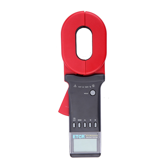
IV. Structure of Meter 1. Long Pincers Jaw : 65mmx32mm 2. Round Pincer Jaw : φ32mm 3. Trigger: to control opening and closing of jaw 4. HOLD Key: lock / Release display / Storage 5. POWER Key: Boot Up / Shutdown /*Quit /Clear Data 6. -
Page 11: Liquid Crystal Display
V. Liquid Crystal Display 1. LCD Screen (1). Alarm Symbol (2). Symbol of low battery & voltage (3). Symbol of full data storage (4). Symbol of data access (5). 2-Digital No. Of Data Storage Unit (6). Current unit (7). Resistance unit (8). -
Page 12: Description Of Special Symbols
2. Description of Special Symbols Note: "*" is limited to C+. ⑴ Symbol of an open jaw: As a jaw is in the open state, the symbol shows. At this point, trigger may be artificially pressed, or the jaws have been seriously polluted, and can no longer continue to measure. -
Page 13: Examples Illustrated
⑽ NOISE signal: when the symbol flashes, in the measurement of grounding resistance at a greater interference current in the loop. At this time it cannot guarantee accuracy of the measurements. 3. Examples Illustrated Note: "*" is limited to C+. ⑴... -
Page 14: Operating Method
the critical value of alarm setting ---Low battery & voltage is displayed. At this time, it not guarantee the accuracy of the measurements ---Measured current is 8.40A ---Lock the current value displayed ---Store the current value as the data Unit No.37 ⑻... -
Page 15: 2.Shutdown
show all of its symbols (Figure 1). Meanwhile the instrument auto-calibration, after boot displayed "OL Ω", automatically enter the resistance measurement mode (Figure 2).If there is no normal boot self-calibration, instrument will show "Er" symbol, said boot error. need to check the cause and reboot (Figure 3). Figure 1 Figure 2 Figure 3... -
Page 16: 3.Resistance Measurement
POWER key or press the AL key for 3 seconds, exit Alarm Critical Value state, then press POWER key to shut down. 3.Resistance Measurement After the booting auto-inspection is completed, it shows "OL Ω" and will be able to proceed with resistance measurement. At this point, press the trigger and open the jaws, clamp the target loop, reading to get the resistance value. -
Page 17: 4.Current Measurement
exceeds the resistance of Alarm Critical Value. In the HOLD state, need to press HOLD key to exit the HOLD state, then continue measurement. In the MR state, need to press MEM key to exit the MR state, then continue to measurement. In setting Alarm Critical Value state, need to press the POWER key or press the AL key for 3 seconds, exit Alarm Critical Value state, then continue to measurement. -
Page 18: 5.Date Lock/Release/Storage
In the MR state, need to press MEM key to exit the MR state, then continue to measurement. In setting Alarm Critical Value state, need to press the POWER key or press the AL key for 3 seconds, exit Alarm Critical Value state, then continue to measurement. -
Page 19: 6.Data Access
6.Data Access Press MEM key to enter Data Access Model, the default display stored in the first 01 Units of data, shown in Figure 11. Then the right arrow keys, up, read the data stored, press the left arrow key, scroll down to the data stored. -
Page 20: 8.Access To Alarm Critical Value
alarm symbol, also issued intermittent "beep--beep--beep--" sound. Setting process, press POWER key to exit Alarm Critical Value setting function, return to measurement status, does not change the previous settings. In data access model, press MEM key to exit, then setting Alarm Critical Value. -
Page 21: Measurement Principle
VII. Measurement Principle 1. Principle of Resistance Measurement The basic principle of ETCR in the measurement of resistance is to measure the loop resistance, as shown in the figure below. The jaw part of the Meter is comprised of voltage coil and current coil. The voltage coil provides excitation signal, and will induce a potential E on the measured loop. -
Page 22: Measurement Method Of Earth Resistance
VIII. Measurement Method of Earth Resistance 1. Multi-Point Grounding System As for the multi-point grounding system (such as electricity transmission tower grounding system, grounding cable communications systems, certain buildings, etc.), They usually pass the overhead ground wire (cable shielding layer) connected to form a grounding system. -
Page 23: Limited Point Grounding System
measured should be R1. Times of comparing tests in different environments and different occasions with the traditional method proved that the above assumption is entirely reasonable. 2. Limited Point Grounding System This is also quite common. For example, in some towers, five towers are linked with each other through overhead ground wire;... -
Page 24: Single-Point Grounding System
And the program would output the same number of grounding resistance values. 3. Single-Point Grounding System From the measuring principle, ETCR series Meter can only -21-... - Page 25 measure the loop resistance, and the single-point grounding is not measured. However, users will be able to use a testing line very near to the earth electrode of the grounding system to artificially create a loop for testing. The following presented is two kinds of methods for the single-point grounding measurement by use of the Meter.
- Page 26 So, if the measurement value of the Meter is smaller than the allowable value of the grounding resistance, then the two grounding bodies are qualified for grounding resistance. (2) Three-Point Method As shown in the figure below, in the vicinity of the measured grounding body R find two independent grounding bodies of better grounding state R...
-
Page 27: Bill Of Loading
In the above three steps, the reading measured in each step is the value of the two series grounding resistance. In this way, we can easily calculate the value of each grounding resistance: From: R1=RA+RB R2=RB+RC R3=RC+RA We get: RA=(R1+R3-R2)÷2 This is the grounding resistance value of the grounding body R To facilitate the memory of the above formula, these three grounding bodies scan be viewed as a triangle;... -
Page 28: Parts List And Assembly Details
X. Parts List and Assembly Details 1. Parts List NAME Part Quantity/PCS Remark Screws battery DS01 M3X8 cover AA alkaline batteries DS02 Battery cover DS03 Upper shell DS04 Subjacent shell DS 05 Tension spring DS 06 Clamp DS 07 DS 08 HOLD key DS09 LCD cover... -
Page 29: Assembly Details
2. Assembly Details -26-... -
Page 30: Xi.trouble Shooting
XI.Trouble shooting Symptoms Possible Causes Remedies No batteries. Set the batteries. Install batteries correct Faulty battery polarity polarity. Insufficient capacity of Replace the batteries. battery Poor contact of battery Replace the battery contacts. contacts Wrong battery type Replace with right type. instrument Make a continuity test of test A break in a battery... - Page 31 Symptoms Possible Causes Remedies Poor contact of LCD Re-plug the LCD connect plug connection wire or replace the plug. Indication error Defect of LCD Replace the LCD. (chip of segment, arithmetic Insufficient capacity of point, unit and so Replace the batteries. battery Defect circuit...
- Page 32 Manufactured by ETCR Electronic Technology Company Address: F-3F, No.4 Pengshang Zhifu Road, Jiahe, Baiyun District, Guangzhou, Guangdong, China Post Code: 510440 Tel: (86-20)62199556 62199554 Fax: (86-20)62199550 E-mail: info@etcr.cc Website: www.etcr.cc...
Need help?
Do you have a question about the ETCR2000+ and is the answer not in the manual?
Questions and answers
Unit does not switch on,batteries are good.
If the ETCR2000+ unit does not switch on despite having good batteries, possible issues include:
- Incorrect battery polarity: Ensure batteries are installed correctly.
- Poor contact of battery contacts: Check and clean or replace the battery contacts.
- Wrong battery type: Use the correct battery type.
- A break in the battery harness: Perform a continuity test; replace the harness if no continuity.
- Displaced POWER button: Re-assemble the button.
- Poor contact of power plug: Re-plug or replace the plug.
- Defective PCB or circuit component: Replace the PCB if current consumption is about 100mA or more at 6V.
This answer is automatically generated
CALIBRATION TIME
The calibration for the ETCR2000+ occurs automatically during boot-up. The device performs auto-calibration after pressing the POWER key and shows "OL Ω" upon successful completion. The exact duration of the calibration time is not specified.
This answer is automatically generated