Table of Contents
Advertisement
Quick Links
Advertisement
Table of Contents

Subscribe to Our Youtube Channel
Related Manuals for ETCR ETCR2000E Plus


Summary of Contents for ETCR ETCR2000E Plus
-
Page 3: Table Of Contents
CONTENT I. Attention .................... 1 II. Brief Introduction ................3 III. Specification ..................6 1. Model of Series................6 2. Ranges and Accuracy of Measurement ......... 6 3. Specifications.................. 6 IV. Structure of Meter ................9 V. Liquid Crystal Display ..............10 1. - Page 4 10.Data Upload ................20 VIII. Measurement Principle ............... 21 1. Principle of Resistance Measurement.......... 21 2. Principle of Current Measurement ..........21 IX. Measurement Method of Earth Resistance ........22 1. Multi-Point Grounding System ............. 22 2. Limited Point Grounding System ..........23 3.
-
Page 5: Attention
I. Attention Thank you for purchasing this pincers earth tester from ETCR Electronic Technology Company. In order to make better use of the product, please be certain: ----To read this user manual carefully. ----To comply with the operating cautions presented in this manual. - Page 6 process, and it is normal. 10 The measurement current of the wire should not exceed the upper limit of the Meter. 11 Please take out the batteries in the case of the Meter being idle for a long time. 12 The dismantling, calibration and maintenance the Meter shall be operated by the authorized staff.
-
Page 7: Brief Introduction
II. Brief Introduction ETCR2000E+/ETCR2100E+ Multifunctional Clamp Earth Resis- tance Tester was designed by technical department of ETCR Electronic Technology Company, it can fulfilling historical inquiry and online real-time monitoring through monitoring software, dy- namic display, alarm indicator, and with the functions like historical data access, reading, preservation, report forms, printing and so on. - Page 8 Historical data can saved as .TXT file or .DOC file. ETCR series of Pincers Earth Tester is widely used in the groun- ding resistance measurement of the power, telecommunications, meteorology, oilfield, construction and the industrial and electrical equipment.
- Page 9 as indicated in the figure below. A long jaw is particularly suitable for the occasion of grounding with the flat steel.
-
Page 10: Specification
III. Specification 1. Model of Series Model Jaw Size (mm) Note 65mm×32mm Long Pincers Jaw ETCR2000E+ Φ32mm ETCR2100E+ Round Pincer Jaw 2. Ranges and Accuracy of Measurement Mode Range Resolution Accuracy 0.010Ω-0.099Ω 0.001Ω ± (1%+0.01Ω) 0.10Ω-0.99Ω 0.01Ω ± (1%+0.01Ω) 1.0Ω-49.9Ω 0.1Ω... - Page 11 tion Current Resolution 0.05mA Data memory 99 Sets RS232 interface,software monitor ,data upload, RS232 Interface dynamic display ≤1s Self-checking time ≤50mA Power Consumption Wire length 1.8m(RS232 data wire) ―du—du—du‖ for alarming press AL for on/off;LCD alarm Audible and visible alarm indication Alarm Threshold...
- Page 12 Feature of dimen- CT clamp sion Shift Automatically External magnet / <40A/m;<1V/m electric field Time single 0.5 second measurement Frequency for >1KHz sistance test Frequency for cur- 50/60Hz automatic identification rent test...
-
Page 13: Structure Of Meter
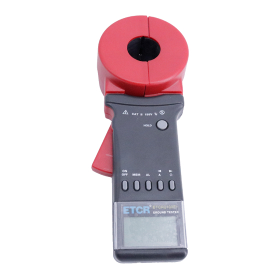
IV. Structure of Meter 1. Long Pincers Jaw : 65mmx32mm 2. Round Pincer Jaw : φ32mm 3. Trigger: to control opening and closing of jaw 4. HOLD Key: lock / Release display / Storage 5.ON/OFF Key: Boot Up / Shutdown /Quit /Clear Data 6. -
Page 14: Liquid Crystal Display
V. Liquid Crystal Display 1. LCD Screen (1). Alarm Symbol (2). Symbol of low battery & voltage (3). Symbol of full data storage (4). Symbol of data access (5). 2-Digital No. Of Data Storage Unit (6). Current unit (7). Resistance unit (8). - Page 15 symbol shows. At this point, trigger may be artificially pressed, or the jaws have been seriously polluted, and can no longer continue to measure. ⑵. ―Er‖ Boot error symbol, May be pressing trigger when boot or jaw has been opened. ⑶.
-
Page 16: Examples Illustrated
measurements. 3. Examples Illustrated ⑴. ---Jaw is in open state, and cannot measure ⑵. ---Boot error instructions Er (Error) ⑶. ---Measured loop resistance is less than 0.01Ω ⑷. ---Measured loop resistance is 5.1Ω ⑸. ---Measured loop resistance is 2.1Ω ---Lock the current measurement value: 2.1Ω... - Page 17 ---Store the current value as the data Unit No.37 ⑻. --- Access to the stored data unit No.8 --- Measured resistance is 30Ω --- This data is measured in a lot of signals interference -13-...
-
Page 18: Function Zoom Table
VI.Function Zoom Table Function Bottom On/off/delay shutdown ON/OFF Lock/cancel display HOLD Exit ON/OFF Resistance/current measurement/data access MODE mode Lock/cancel display/store/access alarm value Set critical value/digital select/access the data have MODE/SET stored Delete all the data have stored SET+MODE VII. Operating Method 1. -
Page 19: 2.Shutdown
to-calibration, after boot displayed "OL Ω", automatically enter the resistance measurement mode (Figure 2).If there is no normal boot self-calibration, instrument will show "Er" symbol, said boot error. need to check the cause and reboot (Figure 3). After Power On and Self Test if not appear "OL Ω",but shows a large resistance (Figure 4). -
Page 20: 3.Resistance Measurement
3.Resistance Measurement After the booting auto-inspection is completed, it shows "OL Ω" and will be able to proceed with resistance measurement. At this point, press the trigger and open the jaws, clamp the target loop, reading to get the resistance value. If the user thinks it necessary, the test can be done with the ring as shown in the following figure 5. -
Page 21: 4.Current Measurement
state, then continue measurement. In the MR state, need to press MEM key to exit the MR state, then continue to measurement. In setting Alarm Critical Value state, need to press the ON/OFF key or press the AL key for 3 seconds, exit Alarm Critical Value state, then continue to measurement. -
Page 22: 5.Date Lock/Release/Storage
In setting Alarm Critical Value state, need to press the ON/OFF key or press the AL key for 3 seconds, exit Alarm Critical Value state, then continue to measurement. In the resistance test model, press A key to switch to current test model. -
Page 23: 6.Data Access
6.Data Access Press MEM key to enter Data Access Model, the default display stored in the first 01 Units of data, shown in Figure 11. Then the right arrow keys, up, read the data stored, press the left arrow key, scroll down to the data stored. -
Page 24: 8.Access To Alarm Critical Value
"beep--beep--beep--" sound. Setting process, press ON/OFF key to exit Alarm Critical Value setting function, return to measurement status, does not change the previous settings. In data access model, press MEM key to exit, then setting Alarm Critical Value. 8.Access to Alarm Critical Value Press AL key to enter the mode of resistance or current mea- surement. -
Page 25: Measurement Principle
VIII. Measurement Principle 1. Principle of Resistance Measurement The basic principle of ETCR in the measurement of resistance is to measure the loop resistance, as shown in the figure below. The jaw part of the Meter is comprised of voltage coil and current coil. The voltage coil provides excitation signal, and will induce a potential E on the measured loop. -
Page 26: Measurement Method Of Earth Resistance
current I The Meter will measure I and the measured current I can be obtained by the following formula. Where: n is the turn ratio of the secondary side vs. primary side. IX. Measurement Method of Earth Resistance 1. Multi-Point Grounding System As for the multi-point grounding system (such as electricity trans- mission tower grounding system, grounding cable communications systems, certain buildings, etc.), They usually pass the overhead... -
Page 27: Limited Point Grounding System
istence of so-called "mutual resistance‖, R is not the usual parallel value in the sense of electrical engineering (slightly higher than its IEC parallel output value). But because a tower-grounding he- misphere was much smaller than the distance between the towers, and with a great number of locations after all, R is much smaller than R... - Page 28 .. .. .. ) 1 Where: R1、R2、……R are grounding resistances of N grounding bodies. 、R 、……R are the resistances measured with the Meter in the different grounding branches. It is nonlinear equations with N unknown numbers and N equations.
-
Page 29: Single-Point Grounding System
3. Single-Point Grounding System From the measuring principle, ETCR series Meter can only meas- ure the loop resistance, and the single-point grounding is not measured. However, users will be able to use a testing line very near to the earth electrode of the grounding system to artificially create a loop for testing. - Page 30 As the resistance value measured by the Meter is the value of the series resistance from the testing line and two grounding resis- tances. Where: R is the resistance value measured with the Meter. is the resistance value of the testing line. Meter can measure out the resistance value by connecting the test lines with both ends.
- Page 31 Second, have R and R linked up, as shown in the following figure. Use the Meter to get the second reading R Third, have R and R linked up, as shown in the following figure. Use the Meter to get the third reading R In the above three steps, the reading measured in each step is the value of the two series grounding resistance.
-
Page 32: Field Application
(3)The application in power station, power substation ETCR series clamp meter can use to test the situation of contact and connect of circuit. With the help of one test line, can be used to test the connect situation of equipment in station and the grounding system. - Page 33 The machine room of telecommunication system normally in the upper deck of the building, and it hard to use the megohm meter to measure. However, it is very convenient to for ETCR. Connect the fire hydrant and the pole being measured by one testing line, then use the meter test the testing line.
- Page 34 If the grounding pole of the buildings is independent with each other, the measurement of grounding resistance of each grounding pole as below: 4. Application in gas station grounding system In the environment where full of explosive gas, such as gas sta- tion, oil field, oil sink have to use explosion proof type.
- Page 35 ble and combustible. (1) The measurement of grounding resistance of tanker and upl- oad and load place As show above, in system of gas station, oil tank grounding pole A connect with tanker, the grounding pole C of load and upload position is a independent grounding pole.
- Page 36 (2) The measurement of grounding resistance of tanker As shows above, find a grounding pole which is independent with tanker, like the grounding pole of upload and load place. Connect these two points by testing line, read the value of R by meter.
-
Page 37: Ⅺ. Matters Need Attention When Measuring Grounding Resistance
This standard is very specific. Like what have mention before, the value measured by ETCR series clamp meter is the grounding resistance of each branch, if the connection of grounding line is good, it is the grounding resis- tance of one grounding body. - Page 38 ETCR series clamp meter doesn’t make any sense. Be- cause what have been measured is different, the big different of the result is make sense. (2).The grounding resistance measured by ETCR series clamp meter is comprehensive resistance of grounding branch. It in- cludes the contact resistance of the public grounding line of this branch, lead line resistance and grounding body resistance.
-
Page 39: Ⅻ. Bill Of Loading
the meter shows ―OL Ω‖, then should change the measuring point. When measuring at B point, the branch being measured i s the circuit of metallic conductor, the meter shows ―L 0.01Ω‖ or the value of resistance of metallic circuit, and the value is very smell When measuring at C point, the value being measured is groun- ding resistance of the branch. - Page 40 Tension spring DS 06 Clamp DS 07 DS 08 HOLD key DS09 LCD cover DS10 DS11 Connect screws of DS12 ST2.9X10 shells Clamp screws DS13 ST2.9X25 Shaft DS14 Push button DS15 Screws for PCB fix DS16 ST2.2X6 Screws for LCD fix DS17 ST2.2X6 -36-...
-
Page 41: Assembly Details
2. Assembly Details XIV. Trouble shooting Symptoms Possible Causes Remedies No batteries. Set the batteries. instrument Install batteries in correct po- Faulty battery polarity cannot be buttoned larity. Insufficient capacity of Replace the batteries. battery -37-... - Page 42 Poor contact of battery Replace the battery contacts. contacts Wrong battery type Replace with right type. Make a continuity test of test A break in a battery lead. If there is no continuity, harness replace the battery harness. Departure Re-assemble the button. ON/OFF button Poor contact of power Re-plug or replace a plug.
- Page 44 Manufactured by ETCR Electronic Technology Company Address: F-3F, No.4 Pengshang Zhifu Road, Jiahe, Baiyun District, Guangzhou, Guangdong, China Post Code: 510440 Tel: (86-20)62199556 62199554 Fax: (86-20)62199550 E-mail: info@etcr.cc Website: www.etcr.cc...
Need help?
Do you have a question about the ETCR2000E Plus and is the answer not in the manual?
Questions and answers