Table of Contents
Advertisement
Quick Links
Advertisement
Table of Contents

Related Manuals for ETCR 9500


Summary of Contents for ETCR 9500
-
Page 2: Table Of Contents
CONTENT I. Safety Precautions And Procedures ..........1 1. Preliminary Instructions ............... 2 2. During Use ................... 2 3. After Use ..................3 II Introduction ..................4 III Electrical Symbols ................6 IV Technical Specifications ..............6 V Structure ....................8 VI Operation ................... -
Page 3: Safety Precautions And Procedures
I. Safety Precautions And Procedures For your own safety and to avoid damaging the instrument you are recommended to follow the procedures described in this manual and read carefully all instructions preceded by this symbol Before and during measurements keep to the following instructions: ●... -
Page 4: Preliminary Instructions
1. Preliminary Instructions ● This instrument has been designer for use in environments with pollution degree 2 ● You are recommended to respect the usual safety regulations aimed at protecting you against dangerous current and protecting the instrument against improper use ●... -
Page 5: After Use
especially when the voltage circuit bears the voltage of AC 100V or more ●It is strictly forbidden to use this meter to test the wire without any insulate protection has voltage exceed 35KV or convergence generatrix. ● In case that the voltage circuit to be tested bearing the voltage over 600V, the Tester shall be applied connecting insulating rod, with the hand holding on the fifth knot of it ●... -
Page 6: Introduction
Soft cloth (e.g. glasses cloth), moistened by clean, antirust and dehumidified lubricant (e.g. WD-40), instead of corrosive agent or rough issues shall be used to gently rub down the Tester ● In case that continuing use will cause safety hazard due to the performance of the Tester itself, stop using it and mothball it at once, then leave it to authorized organization for handling. - Page 7 The HV/LV high accuracy clamp ammeter can be used to measure the current and leakage current varying from 0.01mA to 1000A.HV clamp ammeter can also measure LV current. Current clamp: In order to make sure of the high accuracy, stability and reliability during perennial monitoring, special alloy is selected, latest CT technology and magnetic shield technology are adopted,which make sure almost resistance to external magnetic field.
-
Page 8: Electrical Symbols
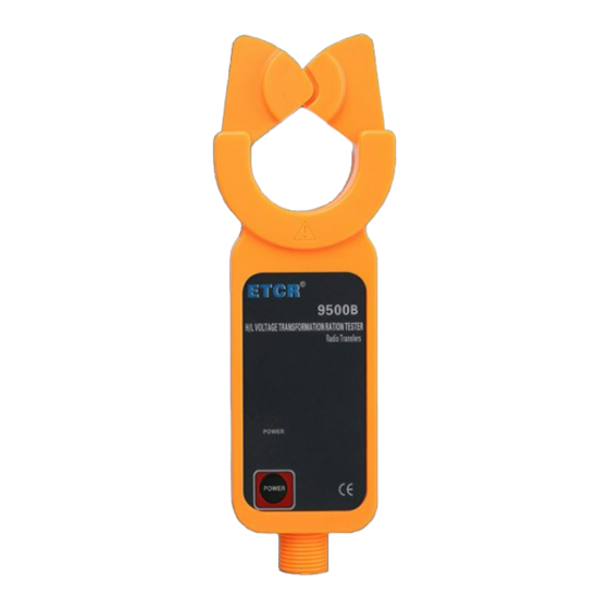
moisture protection, high temperature resistance, shock resistance, bending resistance, high insulation, flexibility and so on. ETCR9500 Wireless HV Current Transformation Ratio Tester is called Wireless Transformation Ratio Tester for high voltage; meanwhile it can function as high/low-voltage clip-on ammeter, for high-altitude current tester, high-altitude leakage current tester, clip-on leakage current meter with high accuracy and other products. - Page 9 Width × Height× Thickness: Main engine: 75mm×170mm×30mm Tester size HV Current Clamp: 76mm×255mm×31mm LC Current Clamp: 175mm×70mm×38mm HV Current Clamp:φ48mm Clamp LC Current Clamp: φ25×30mm Dimension Sampling speed About 3 times/second Measurement High voltage detector: 0.0mA~1000A range Low-voltage current clamp: 0.00mA~10A High voltage detector: 0.1mA Resolution Low-voltage current clamp: 0.01mA...
-
Page 10: Structure
Battery When battery voltage is below 4.8v, sighs will remind voltage you of replacement Main engine: about 240g (including battery) High voltage detector: about 335g (including battery) Weight Low-voltage needle-point current clamp: about 190g Total weight: about 2.5kg(including insulation rod and battery) External No super strong electromagnetic field;... -
Page 11: Operation
①High voltage detector ②Main engine ③Low-voltage current clamp 1 High-voltage current clamp 2 LED power indication of HV detector 3 Power key 4 Joints of insulation rods 5 Input interface for low-voltage current 6 LCD monitor of the main engine 7 HOLD key 8 RS232 Interface 9 Output plug for low-voltage current clamp... -
Page 12: Switch Of Main Engine
2. Switch of main engine Press to start the engine, and LCD displays. After POWER the normal startup, the main engine will enter test receiving mode (see the picture above). The primary current is the testing data of high-voltage terminal while the secondary current the low-voltage. In case that signals are detected in both primary and secondary circuits, the main engine will show the transformation ratios on the basis of secondary circuit bearing current 5A, and indicate phase. -
Page 13: Detection On Hv Current
3. Detection on HV current High voltage, very dangerous!Nobody but a qualified personnel after training could conduct operation on it. The operator should obey safety regulations; otherwise there will be the danger of electric shock resulting in personal injury or casualty. Only when all of the five insulating bars are connected can the high voltage line be detected, otherwise there may be the danger... - Page 14 by the high voltage detector which starts detection and feedback to the main set. Main set enter detection and data collection state after its normal starting up, If the main set receives the signal sent by the high voltage detector, there will be a live indication of current amount on high voltage end, If the main set fails to receive the signal sent by the high voltage detector, the first current is indicated to be”...
-
Page 15: Detection On Lv Current
Notice: For the sake of safety, please take the instrument away from the wire after the detection is finished. 4. Detection on LV current High voltage, very dangerous!Nobody but a qualified personnel after training can conduct operation on it. The operator should strictly follow the safety regulations;... -
Page 16: Transformation Ratio Measurement
Clamp live wire and null line at the same time, leakage current could be detected.(note: total 2 wires) Clamp the earth wire, the leakage current could be measured(note: single wire) Clamp the main line, total current amount could be measured. (note: single wire) Where its numeral reading is not easily accessible, use high voltage detector to examine the current on low voltage wire. - Page 17 measured secondary current value is converted to be 5A, and then convert the first current based on that multiple, which is same with transformation ratio. Display【XXX/5A】 【Ratio】: The ratio between the first current and secondary current by actual measurement. 【 10kV-YYconversion ratio 】 : high voltage detector collects the secondary bus current, The ratio between transformer’s first current and mutual inductor secondary current could be...
- Page 18 detection mode. In the ratio conversion mode, click the key to set the HOLD second time currency base number, and conversion ratio is calculated; press the key to shift the cursor. Press the POWER key for 3 seconds, exit from the conversion ratio display HOLD mode, and return to the start-up detection mode.
-
Page 19: Data Keeping And Delete
6. Data keeping and delete In detection mode, press the key for LCD display of HOLD symbol. Press the key to release the data lock, HOLD HOLD return to the detection mode, the “ ” symbol disappears. HOLD 7. Data storage In detection mode, press the key for data holding, HOLD... -
Page 20: Data Deletion
9. Data deletion In data search mode, press the POWER key and shift the cursor to the “delete DEL” position, then press the HOLD key “YES” to delete all the stored data, and return to detection mode, it is not possible to restore the data been deleted. VII Software The monitor and data upload software have to be installed and run on the computer base on Windows XP/2000 OS. -
Page 21: Historical Data Page
Curve zooms in and out: Click the left key (no release) of the mouse and move the mouse. 2. Historical data page Historical data process: read, access, saving, analysis, Sequence,draw curve, print. VIII Replace battery Caution! No detection could be conducted when the battery cover is not properly closed, otherwise there is danger. -
Page 22: Accessories
replace with new qualified batteries. Paying special attention to the size and electrode, close the battery cover, tighten the two screws. 3. Press the key to examine whether the instrument is POWER normally stared up, if not, repeat the operation according to step 2. - Page 24 Manufactured by ETCR Electronic Technology Company Address: F-3F, No.4 Pengshang Zhifu Road, Jiahe, Baiyun District, Guangzhou, Guangdong, China Post Code: 510440 Tel: (86-20)62199556 62199554 Fax: (86-20)62199550 E-mail: info@etcr.cc Website: www.etcr.cc...
Need help?
Do you have a question about the 9500 and is the answer not in the manual?
Questions and answers