Table of Contents
Advertisement
Advertisement
Table of Contents

Related Manuals for ETCR 3000B


Summary of Contents for ETCR 3000B
- Page 1 Earth Resistance Soil Resistivity Tester ETCR Electronic Technology Company...
-
Page 2: Table Of Contents
CONTENT Warning....................0 I.Introduction...................2 II.Technical Specifications............3 1. Base Conditions and Working Conditions......3 2. General Specification..............3 3. Intrinsic error and performance indicators under base conditions..................5 III. Tester Structure............... 6 IV.LCD Display................7 V.Measuring Principle..............8 VI. Operation Methods..............9 1.Switch On/Off............... 9 2.Battery Voltage Check............9 3.AC Voltage Measurement........... -
Page 4: Warning
Warning Thanks for your purchase of ETCR3000B Earth Resistance Soil Resistivity Tester of our company. For better use of the product, please make sure: ---to read this user manual in details. ---to abide by the safety regulations and precautions strictly. ... - Page 5 Please don’t keep or store the tester in the spot with high-temperature and moisture, or condensation, and under direct daylight radiation for a long time. If the instrument is damp, please dry it before keeping. For replacing battery, please confirm testing wire has moved apart the meter, and FUNCTION rotary switch is in “OFF”...
-
Page 6: I.introduction
I.Introduction ETCR3000B Earth Resistance Soil Resistivity Tester is specially designed and manufactured for measuring earth resistance, soil resistivity, earth voltage, AC voltage. Adopting the latest digital and micro-processing technology, precise 4-pole, 3-pole and simple 2-pole method for earth resistance measurement, importing FFT and AFC technology, with a unique function of anti-interference capability and the ability to adapt to the environment, consistency of repeat testing, to ensure high precision, high stability and reliability for prolonged... -
Page 7: Technical Specifications
II.Technical Specifications 1. Base Conditions and Working Conditions Base Working Influence Quantity Remark Condition Conditions Ambient Temp 23℃±1℃ -10℃-40℃ ---- Ambient Humidity 40%-60% ---- <80% Working Voltage 9V±0.1V 9V±1.5V rC、rP Auxiliary Earth ---- <100Ω <30kΩ Resistance Interference Voltage ---- <20V Interference Current <2A Electrode Distance... - Page 8 Earth resistance: 0.00Ω-30.00kΩ, automatic shift Shift Soil Resistivity: 0.00Ωm-9000kΩm, automatic shift Backlight Blue screen backlight, suitable for dim places 4-digital super-large LCD display, blue screen Display Mode backlight Measuring During measurement, LED flash indicator, LCD count Indicator down display, progress bar indicator LCD Frame 128mm×75mm Dimension...
-
Page 9: Intrinsic Error And Performance Indicators Under Base Conditions
battery voltage low icon will display, reminding to replace battery. Standby: about 20mA (Backlight shut off) Power Boot and with backlight: about 45mA (25mA without Consumption backlight) Measurement: about 100mA (Backlight shut off) Total weight: 4.5kg (including package) Tester: 1443g (including battery) Weight Tesing wires: 1560g Auxiliary earthing rods: 935g (4pcs) -
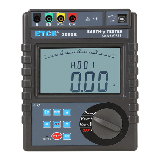
Page 10: Tester Structure
1000Ωm-9999Ωm 1Ωm ρ=2πaR 10.00kΩm-99.99kΩm 10Ωm a:1 m-100m, 100.0kΩm-999.9kΩm 100Ωm π=3.14) 1000kΩm-9000kΩm 1kΩm Earth Voltage AC 0.0-600V ±2%rdg±3dgt 0.1V Note: 1. When rC max or rP max, additional error≤±3%rdg±5dgt. (rC max: 4kΩ+100R<50kΩ, rP max: 4kΩ+100R<50kΩ) 2. When 5V interference voltage, additional error≤±5%rdg±5dgt. III.... -
Page 11: Lcd Display
IV.LCD Display 1. Progress bar (Dynamic display the progress of testing) 2. Alarm symbol (Display when open alarm function, flash when exceed the alarm value) 3. Exceed voltage symbol (Display when the measured voltage exceed 30V, please pay attention to the safety) 4. -
Page 12: Measuring Principle
V.Measuring Principle 1. Voltage to ground measurement adopts average value rectification method. 2. Earth resistance measurement with fall-of-potential method. AC constant current I is applied between the measurement object E earth electrode and C current electrode, and finding out the potential difference V between E earth electrode and P voltage electrode, calculating the earth ground R according to formula R=V/I. -
Page 13: Operation Methods
current electrode, find the potential difference V between P voltage electrode and ES auxiliary earthing electrode, the potential difference V divided by AC current I is earth resistance R, electrode distance is a(m), then soil resistivity can be got according to formula ρ=2πaR(Ωm). -
Page 14: 3.Ac Voltage Measurement
3.AC Voltage Measurement Ac line voltage measurement can't exceed 600 V. Connect P and ES interface to test commercial AC voltage, no need to connect C and E interface. AC voltage measurement refers to the general commercial AC voltage measurement, pay attention to the difference between grounding voltage, the meter can be used for testing below 600V AC line voltage. -
Page 15: 4.Earth Voltage Measurement
4.Earth Voltage Measurement Earth voltage measurement need to use one auxiliary earthing rod. The meter connect with the earth only by testing wires and auxiliary earthing rods. Other testing wires of meter’s interface can’t connect with commercial power line L, N, otherwise may cause leakage, the breaker may start, it is dangerous. -
Page 16: 5.4-Wires Precise Earth Resistance Measurement
5.4-wires Precise Earth Resistance Measurement In the testing of earth resistance, should firstly confirm the earth voltage of earthing wire, the voltage between and E or P(s) and ES must under 20V, the meter showing NOISE symbols when the earth voltage exceed 5V, and the measured value of earth resistance may produce error. - Page 17 Green Black Yellow Measured Grounding For multi independent earthing system or larger earth net, 50m or longer testing wire is optional, as shown below: Black Green Yellow -13-...
- Page 18 R=r1∥r2∥r3∥r4∥r5∥r6∥…∥rn (r1…rn are all independent earthing points) R—— The reading value on meter, the total earth resistance of the earthing system. r1…rn—— All are independent earthing points, each points have no connection together under the ground. rC—— The earth resistance rC of auxiliary current electrode C (H).
-
Page 19: 6.3-Wires Earth Resistance Measurement
6.3-Wires Earth Resistance Measurement 3-wires measurement: As shown below, short-circuit ES and S interface, which is 3-wires measurement. The operation of meter is the same with 4-wires measurement. The 3-wires method can’t eliminate influence of line resistance, also can’t eliminate influence of contact resistance between meter and testing wires, testing wires and auxiliary Grounding rods. - Page 20 others to replace auxiliary earthing rods C , and pay attention to remove oxide layer on the connection point of the selected metal auxiliary earthing object when making measurement. Wire connection is as following figure, and refer to 4-wires measurement for other operations. Transformer Secondary Primary...
-
Page 21: 8.Soil Resistivity Measurement
like commercial use power system. Then, the earth ground resistance value of measured earthing object is: RX=R-re 8.Soil Resistivity Measurement Soil resistivity ρ is a determining factor of earthing resistance of earthing body. Different nature of the soil, there is a different soil resistivity. -
Page 22: 9.Backlight Control
mode. After setting a value, in soil resistivity testing mode, press the “START” button to start testing, and countdown display testing process, stable soil resistivity value is shown when finish testing. As shown below, the measured soil resistivity is 53.38Ωm, already stored 157 sets of data. -
Page 23: 12.Data Reading/Deletion
12.Data Reading/Deletion In test mode, press button for a longer time (over 3 seconds) to enter data reading, press button to select reading data group number by step value 1, press button constantly to select reading data group number by step value 10. When the current data is earth resistance or soil resistivity, press “... -
Page 24: Accessories
VIII.Accessories Tester 1 PC Tester Bag 1 PC Auxiliary Earthing Rod 4 PCS Standard testing Wire 4 wires: each for red 20m, black 20m, yellow 10m, and green 10m Simple testing Wire 2 wires: each for red 1.6m and black 1.6m Monitoring Software Disk 1 Copy RS232...
Need help?
Do you have a question about the 3000B and is the answer not in the manual?
Questions and answers