
Related Manuals for Baumer PF55S


Summary of Contents for Baumer PF55S
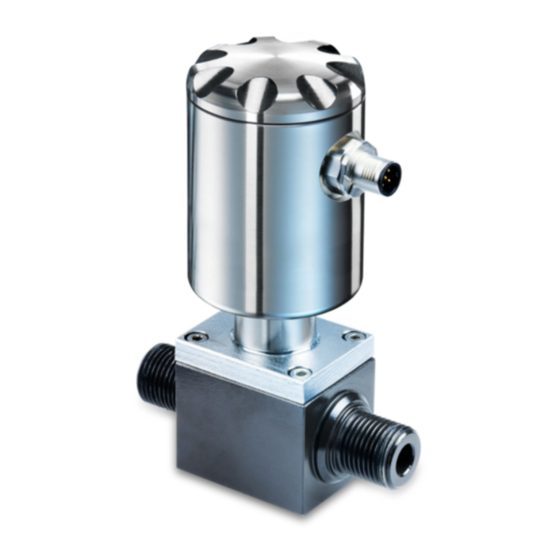
- Page 1 Operation manual Flow sensor PF55S Read this manual prior to performing any task! Translation of the original German document, dated 4/3/2020 English...
- Page 2 Baumer Electric AG Hummelstrasse 17 CH – 8501 Frauenfeld Telephone: +49 777164741222 E-mail: mid.de@baumer.com Internet: www.baumer.com Translation of the original operation manual PF55, 4, en_US © Baumer 2020 Flow sensor PF55S 05.03.2020...
- Page 3 Supplemental directives Information on the operating This manual is an integral part of the PF55S and must be kept manual within close proximity of the system for personnel to access at all times. This manual enables the device to be handled safely and efficiently.
- Page 4 Supplemental directives Copyright protection Baumer Group operating manuals and handbooks are protected by copyright. The copying, reproduction and translation, etc. of them is prohibited. Additional copies of this operating manual and copies in other languages can be obtained directly from Baumer.
-
Page 5: Table Of Contents
5.3 Installation..............35 5.4 Electrical connection........... 38 Commissioning..............41 6.1 Create USB interface..........41 6.2 BCP software installation..........42 Operation................47 7.1 BCP Software............. 47 7.2 Visualization view............50 7.3 Quick start menu............53 7.4 Access codes.............. 53 05.03.2020 Flow sensor PF55S... - Page 6 Maintenance..............92 8.1 External cleaning............92 8.2 Internal cleaning............92 8.3 Replacing the seals............ 92 Fault elimination............... 93 9.1 Alarms................. 93 9.2 Error messages............95 Disassembly and disposal..........97 Technical data..............98 Replacement parts............102 Index................. 103 Flow sensor PF55S 05.03.2020...
-
Page 7: General
General General This operating manual is valid for the magnetic-inductive flow sensor PF55S. 05.03.2020 Flow sensor PF55S... -
Page 8: Safety And Responsibility
Safety guidelines may relate to particular, individual instructions. tions Such safety guidelines are embedded within the instructions so that they do not interrupt the reading flow when performing opera- tions. The signal words described above are used. Example: Flow sensor PF55S 05.03.2020... - Page 9 Lists without a specified order [Enter] Screen elements (e.g. switch areas, layout of function buttons) Operating elements (e.g. buttons, switches) Display Screen elements (e.g. menu titles, window descriptions) Function Screen elements (e.g. Interface texts) 05.03.2020 Flow sensor PF55S...
-
Page 10: Designated Use
Safety and responsibility Work areas and danger zones 2.2 Designated use The flow sensor PF55S is exclusively intended for use in confined spaces within industrial working environments. Proper application also includes adherence to all information given in this manual. This relates in particular to adherence to the tech- nical information. -
Page 11: Safety Marking
2.7 Responsibility of the owner Owner The owner is the person who operates or owns the sensor PF55S, or who has assumed the decisive economic authority over the technical operation of the equipment. Normally, the owner is not Baumer, but rather the purchaser of the sensor PF55S. - Page 12 He must produce operating instruc- tions for handling the operations and process equipment safely. Throughout the entire operating life of the PF55S, the oper- ating company must check whether the operating instructions he created correspond with the latest regulations and must adjust them as necessary.
-
Page 13: Integrator Responsibilities
The operating company’s desired installation position for the sensor PF55S in the higher-level machine could differ from the Baumer assumed installation conditions. Example: The operator may not be able to use the sensor without risk because of a conveying element in the higher-level machine. -
Page 14: Immediate Measures Following An Accident
Immediate measures following an ... The integrator must conduct a risk assessment that covers the following areas: – Installation of the sensor PF55S in the higher-level machine and any associated interface resulting from this. – Any change to the protection measures required due to installation of the sensor PF55S in the higher-level machines. - Page 15 Level of moisture of the skin Size of the contact surface It can include heart rhythm disturbances, ventricular fibrillation and burn injuries due to the arcing effect. It is always advisable to con- sult a doctor. 05.03.2020 Flow sensor PF55S...
-
Page 16: Personnel Requirements
Risk of injury if personnel are insufficiently quali- fied Application of the required specialist knowledge for the PF55S. Inadequate or missing personnel qualification increases the risk of an accident. This can result in severe injuries and substantial property damage. Hazards arise that can result in serious injuries and... - Page 17 A qualified mechanic has been specially trained in the working environment in which he operates and knows the relevant stand- ards and regulations. A qualified mechanic is also familiar with the superordinate production system. 05.03.2020 Flow sensor PF55S...
-
Page 18: Personal Protective Equipment
Personal protective equipment serves to protect people from equipment impairments to health and safety during work. During different types of work on and with the PF55S, personnel must wear the personal protective equipment specifically referred to in the individual sections of this manual. -
Page 19: Safety Guidelines For Transport And Storage
This can result in considerable material damage. – Proceed with care when unloading transport items upon delivery and during internal transport. – Follow the symbols and information on the pack- aging. – Do not remove packaging until shortly before assembly. 05.03.2020 Flow sensor PF55S... -
Page 20: Safety Guidelines For Assembly And Commissioning
– Always determine installation locations to account for hazard-free access and operation. – Assemble all of the components correctly. – Always follow the operation and assembly manuals for additional components. Flow sensor PF55S 05.03.2020... - Page 21 The individuals must have read and understood this operating manual. – The individuals must follow the instructions in this operating manual. – The individuals must have the necessary spe- cialist skills for such assembly and installation. 05.03.2020 Flow sensor PF55S...
- Page 22 Risk of material damage due to contamination Contamination can cause material damage by affecting system components. – Always cover at-risk parts of the equipment before work such as drilling. – Always collect dust and shavings immediately throughout the assembly process. Flow sensor PF55S 05.03.2020...
-
Page 23: Safety Guidelines For Maintenance And Resolving Faults
– Personnel must have read and understood this operating manual. – Personnel must follow the instructions in this operating manual. – Personnel must have the necessary specialist skills for such maintenance. 05.03.2020 Flow sensor PF55S... -
Page 24: Safety Information For Replacement Parts
Hazards for personnel, as well as damage, malfunc- tions or a total failure can occur due to the use of incor- rect or faulty replacement parts. – If you have any questions, always contact Baumer. Flow sensor PF55S 05.03.2020... - Page 25 Warranty Invalidation of the warranty The warranty become null and void if unauthorized replacement parts are used. Acquisition of replacement parts Replacement parts can be acquired from local contact partners or direct from Baumer at www.baumer.com. 05.03.2020 Flow sensor PF55S...
-
Page 26: Layout And Functional Description
The higher the liquid velocity, the higher the induced voltage. The voltage signal is converted by the integrated electronics of the transmitter based on the nominal size in flow volume. Flow sensor PF55S 05.03.2020... -
Page 27: Ports
Ä 5.3 “Installation” on page 35 The transmitter cover can be unscrewed. The USB port of the flow sensor for connection to a PC is underneath this cover. Ä 6.1 “Create USB interface” on page 41 05.03.2020 Flow sensor PF55S... -
Page 28: Control Software Bcp
Layout and functional description Control software BCP 3.4 Control software BCP The BCP control software is used to configure and operate the flow sensor. Ä 7.1 “BCP Software” on page 47 Flow sensor PF55S 05.03.2020... -
Page 29: Transport And Storage
For this reason, do not destroy the packaging. The PF55S is packed in accordance with the expected transport conditions. The packaging size and material can vary depending on the total delivery volume. - Page 30 Always dispose of the packaging materials in an eco-friendly manner. – Always observe the locally applicable disposal reg- ulations. Instruct a specialist company to undertake disposal, if necessary. The recipient is responsible for any costs associated with the disposal. Flow sensor PF55S 05.03.2020...
-
Page 31: Assembly And Installation
Mechanical effects on the flow sensor must be excluded during operation. During installation, the recommended and avoidable installa- tion positions of the flow sensor must be observed: Ä 5.2 “Installation position of the flow sensor” on page 32 05.03.2020 Flow sensor PF55S... -
Page 32: Installation Position Of The Flow Sensor
Only the signs for the KA parameters in the control soft- ware have to be changed. Ä 7.6.1 “Sensor menu” on page 60 Recommended installation position Always bear the following in mind when choosing the installation position of the flow sensor: Flow sensor PF55S 05.03.2020... - Page 33 When installing the flow sensor vertically, installation in a rising pipe is preferable. Consultation may be required prior to installation in a falling line. When installing the flow sensor in long lines, anti-vibration compensators should be used. 05.03.2020 Flow sensor PF55S...
- Page 34 The flow sensor must not be connected to other fittings by tightening clamps. Installation positions to be avoided The following installation positions must be avoided: No installation directly in front No installation in a falling line. of a falling line. Flow sensor PF55S 05.03.2020...
-
Page 35: Installation
Qualified mechanic Protective equipment: Protective work clothing Safety boots DANGER! Risk of injury when entering the operating space of the super-ordinate machine and its moving parts CAUTION! Risk of injury due to improper assembly and instal- lation 05.03.2020 Flow sensor PF55S... - Page 36 There must be enough space for the flow sensor and the infeed and outfeed sections at the installation site of the sensor. The required seals and flanges must be present. Any necessary transition pieces and fittings must also be present. All connections must be clean. Flow sensor PF55S 05.03.2020...
- Page 37 All torques must be observed during assembly. Check the piping system for leaks in the area of the flow sensor. Connect the flow sensor electrically. Ä 5.4 “Electrical connection” on page 38 ð The flow sensor PF55S is installed. 05.03.2020 Flow sensor PF55S...
-
Page 38: Electrical Connection
Output 1 Output 2 (optional) 4 - 20 mA maximum load: 500 Ω output (optional) Power supply outputs Shielding PIN 5/6 must be used to establish the grounding connection Electrical pin assignment with plug-in connection (M12) Flow sensor PF55S 05.03.2020... - Page 39 All electrical connections are clean. Ensure the higher-level machine is securely switched off with the power disconnected. Disconnect the higher-level machine from the mains if neces- sary and ensure it cannot be switched back on unintention- ally. 05.03.2020 Flow sensor PF55S...
- Page 40 (VEC): 100 Isolation of other secondary circuits: 500 V Maximum load at 30 V: 500 Ω Update frequency corresponds to the sampling frequency Protected against permanent overvoltages up to 30 V Fig. 3: Output 4 Flow sensor PF55S 05.03.2020...
-
Page 41: Commissioning
Risk of injury when entering the operating space of the super-ordinate machine and its moving parts The flow sensor must be connected to a PC via the USB port in order to install the BCP software with all drivers. 05.03.2020 Flow sensor PF55S... -
Page 42: Bcp Software Installation
The BCP software can be incorrectly recognized or blocked by the firewall or the virus protection program as malware. In this case, the BCP.exe file must be released man- ually in the firewall or the virus protection program. Flow sensor PF55S 05.03.2020... - Page 43 Start the BCP.exe file as administrator. ð Two error windows are opened. The error windows indicate missing drivers. These drivers are loaded and installed during the installation process. The windows can be closed by pressing the [OK] switch area. 05.03.2020 Flow sensor PF55S...
- Page 44 [YES] switch area. ð The BCP software is automatically updated to the latest version. Open the Tools menu. Open the installation window by selecting the [Install ...] menu option. ð The installation window opens. Flow sensor PF55S 05.03.2020...
- Page 45 A window opens with corresponding instructions. Disconnect the USB interface of the flow sensor from the Restore the USB interface of the flow sensor to the PC. Close the window by pressing the [OK] switch area. 05.03.2020 Flow sensor PF55S...
- Page 46 Commissioning BCP software installation Close the installation window by pressing the [X] switch area. ð The BCP software is installed with all drivers. The flow sensor can be configured. Ä 7.1 “BCP Software” on page 47 Flow sensor PF55S 05.03.2020...
-
Page 47: Operation
The flow sensor is connected to a PC via the USB port. Ä 6.1 “Create USB interface” on page 41 The BCP software is installed on the PC with all drivers. Ä 6.2 “BCP software installation” on page 42 05.03.2020 Flow sensor PF55S... - Page 48 Ä “BCP command input” on page 50 Visualization view and menu The visualization view graphically displays system values and messages. The visualization view also enables access to the quick start menu and main menu. Ä 7.2 “Visualization view” on page 50 Flow sensor PF55S 05.03.2020...
- Page 49 Menu for uploading the list In the menu, saved or edited lists can be uploaded and read in. Folder path to save the lists The folder path for saving and loading lists is selected in this input field. 05.03.2020 Flow sensor PF55S...
-
Page 50: Visualization View
The functionality and available capabilities of the flow sensor vary depending on the order configuration and type code. Depending on the configuration of the flow sensor or activated functions, individual menus and selection functions may differ from the representations or be hidden. Flow sensor PF55S 05.03.2020... - Page 51 Ä 7.6.2 “Units menu” on page 62 Current scale end value Ä 7.6.3 “Scales menu” on page 66 Resistance value of the sensor electrodes Positive part counter Negative part counter Positive total counter Negative total counter Net total counter 05.03.2020 Flow sensor PF55S...
- Page 52 Overflow Impulse 1 (Pictogram flashes) Alarm Overflow Impulse 2 (Pictogram flashes) Signal error Excitation error The complete list of all error messages and alarms can be found in the section Faults: Ä 9 “Fault elimination” on page 93 Flow sensor PF55S 05.03.2020...
-
Page 53: Quick Start Menu
If the Restr.access function is disabled, then the menus and functions corresponding to the level of the access code and all the lower password levels can be accessed. 05.03.2020 Flow sensor PF55S... -
Page 54: Operation: Example
Open the quick start menu by pressing [Enter]. ð The menu for inputting the access code will open. Enter the access code. Use the [Left/Right] arrow keys to enter the characters. Use the [Up/Down] arrow keys to select the number. Flow sensor PF55S 05.03.2020... - Page 55 Set the value for the scale end value with the [Up/Down] arrow keys. Confirm the amended scale end value by pressing [Enter]. ð The scale end value has been changed. Close the quick start menu by pressing [ESC]. ð The display changes to the Visualization view. 05.03.2020 Flow sensor PF55S...
-
Page 56: Operation: Example Main Menu
Use the [Up/Down] arrow keys to select the number. Confirm the access code entry by pressing [Enter]. ð The quick start menu opens. Select the Main menu with the [Up/Down] arrow keys. Open the Main menu by pressing [Enter]. ð The Main menu opens. Flow sensor PF55S 05.03.2020... - Page 57 Select the value for the scale end value with the [Left/Right] arrow keys. Set the value for the scale end value with the [Up/Down] arrow keys. Confirm the amended scale end value by pressing [Enter]. ð The scale end value has been changed. 05.03.2020 Flow sensor PF55S...
-
Page 58: Menu Navigation
Ä 7.6.5 “Alarms menu” on page 71 Ä 7.6.6 “Inputs menu” on page 73 Inputs Ä 7.6.7 “Outputs menu” on page 75 Outputs Ä 7.6.8 “Communication menu” Communication on page 79 Display Ä 7.6.9 “Display menu” on page 80 Flow sensor PF55S 05.03.2020... - Page 59 Ä 7.6.12 “System menu” on page 87 The following menus are also available as an BCP command in the command input of the BCP software: Menu Description Ä 7.6.13 “Process data menu” Process data on page 90 05.03.2020 Flow sensor PF55S...
-
Page 60: Sensor Menu
Sensor diameter PDIMV Selection of the sensor diameter: 0 – 2500 (DN see type plate) Calibration coefficient CFFKA Calibration coefficient for negative flow CFFKN This function is only displayed if at least one negative calibration coefficient is set. Flow sensor PF55S 05.03.2020... - Page 61 For zero calibration, make sure that the meas- uring pipe is completely filled with liquid and the liquid is completely still. Even the smallest movements of liquid can cause considerable measuring errors. 05.03.2020 Flow sensor PF55S...
-
Page 62: Units Menu
Flow rate measuring system FRMUT Metric measurement system Anglo-American measurement system Pl1 unit Measurement system for Impulse 1 PL1UT Metric measurement system Anglo-American measurement system Pl2 unit Measurement system for Impulse 2 PL2UT Metric measurement system Anglo-American measurement system Flow sensor PF55S 05.03.2020... - Page 63 Value 1 generates 0.0 in the display Value 2 generates 0.00 in the display Value 3 generates 0,000 in the display P- unit Measurement system for negative part TPNUT counter Metric measurement system Anglo-American measurement system 05.03.2020 Flow sensor PF55S...
- Page 64 Decaliters metric Hectoliters metric m³ Cubic meters metric Megaliters metric in³ Inch not metric American gallon not metric ft³ Cubic feet not metric Standard barrel not metric Oil barrel not metric British gallon not metric Flow sensor PF55S 05.03.2020...
- Page 65 Operation Menu navigation > Units menu Weight units: Gram metric Kilograms metric metric Ounce not metric American pound not metric American ton not metric 05.03.2020 Flow sensor PF55S...
-
Page 66: Scales Menu
Channel 1. Tpls1 Duration of the pulse generated at Channel OP1PT The value sets the duration of the pulse gener- ated at Channel 1. It can be anywhere between 0.4 and 9999.99. Flow sensor PF55S 05.03.2020... - Page 67 Channel 2. Tpls2 Duration of the pulse generated at Channel OP2PT The value sets the duration of the pulse gener- ated at Channel 2. The value can be between 0.4 and 9999.99 mil- liseconds. 05.03.2020 Flow sensor PF55S...
-
Page 68: Measure Menu
(such as tube vibration) from increasing the total meter. The threshold can be0 - 25% of the set scale end value. A value between 0.5 and 1 % is recommended for most applications. Flow sensor PF55S 05.03.2020... - Page 69 With this adaptive damping filter, the sensor can respond very quickly to changes in flow, while being precise and stable with slow fluctuations in flow. Damping filter deactivated With inactive damping OFF, successive values cause an increasing damping of the measured values. 05.03.2020 Flow sensor PF55S...
- Page 70 Input noise filter with high immunity to HIINP noise filter interference When this feature is enabled, an immunity to measurement is activated that is approximately Dynamic sample Dynamic analysis DINSA analysis Dynamic sample time Dynamic analysis time DYNST Flow sensor PF55S 05.03.2020...
-
Page 71: Alarms Menu
The value of this parameter is set as a per- centage (0 - 125%) of the scale end value. If the parameter is 0, the alarm generation is deactivated. 05.03.2020 Flow sensor PF55S... - Page 72 10% so that the maximum deviation is a maximum of 2 mA in all cases. Hz v.alarm Alarm value for frequency value OFACV The value is set as a percentage (0 - 125%) of the frequency. Flow sensor PF55S 05.03.2020...
-
Page 73: Inputs Menu
Meas.lock Stop measurement MSLIE If the function is activated, the measurement can be stopped by an external signal. The meter indicates zero flow. 05.03.2020 Flow sensor PF55S... - Page 74 Range change Change of the measuring range SRCIE If the function is activated, the measuring range can be changed by an external signal. This function cannot be activated if the Autorange function is activated. Flow sensor PF55S 05.03.2020...
-
Page 75: Outputs Menu
DISABLE MAX AL. + MAX DIRECT FLOW RATE OUTPUT (ENERGIZED = AL. OFF) MIN AL. + MIN DIRECT FLOW RATE OUTPUT (ENERGIZED = AL. OFF) MAX AL.- MAX INVERSE FLOW RATE OUTPUT (ENERGIZED = AL. OFF) 05.03.2020 Flow sensor PF55S... - Page 76 + = positive flow direction – - = negative flow direction – blank = both flow directions – 0 = zero flow The values that correspond to the update points are shown in the following table: Flow sensor PF55S 05.03.2020...
- Page 77 Out.mA = 0 – 22 (-) Out.mA = 4 – 20 (-) Out.mA = 21.6 4 – 22 (-) Out.mA = 0 – 20 Out.mA = 0 – 22 Out.mA = 4 – 20 Out.mA = 21.6 21.6 4 – 22 Out.mA = 0 – 20 –0 (+) Out.mA = 0 – 22 –0 (+) 05.03.2020 Flow sensor PF55S...
- Page 78 ≤ - 110 % - 100 % 0 % + 100 % ≥ + 110 % Out.mA = 4 – 20 –0 (+) (Example 2) Out.mA = 4 – 22 –0 (+) Example 1 Fig. 6: Out.mA = 4 – 22 + Example 2 Fig. 7: Out.mA = 4 – 20 –0+ Flow sensor PF55S 05.03.2020...
-
Page 79: Communication Menu
Depending on the configuration of the flow sensor or activated functions, individual menus and selection functions may differ from the representations or be hidden. Menu Description Password level / BCP command HART pr. HART data packet preamble HARTP Dev.Addr Device communication address DVADD 05.03.2020 Flow sensor PF55S... -
Page 80: Display Menu
Net tot. Function net counter NVTTE If this function is active, the net counter is dis- played in the visualization view. Quick start Quick start menu QSTME This function is used to enable or disable quick start. Flow sensor PF55S 05.03.2020... -
Page 81: Functions Menu
SFDSD Save Conv.f.def. Saving the factory setting of the transmitter SFDCD Calibration Performing a circuit calibration CALIC When the function is activated, the message EXECUTE is displayed. Pressing and holding the Enter key completes the calibration. 05.03.2020 Flow sensor PF55S... -
Page 82: Diagnostic Menu
With this function, it is possible to generate an internal signal that simulates the flow rate. The outputs and all connected instruments can be tested this way. Display measures Diagnostic values DMVLS Enabling this feature displays a list of internal parameters. Flow sensor PF55S 05.03.2020... - Page 83 Logging of all event information DIAGF With this function different functions and prop- erties can be tested with the help of a code. Example: DIAGF = 80 -> FORCE OUT 1 TO COPY THE STATE OF THE IN2 05.03.2020 Flow sensor PF55S...
- Page 84 FORCE OUT 2 TO OUTPUT 64 HZ 1536 (SUB-CLOCK CHECK) OUT2 DIAG BITS DIAGNOSTIC BITS FOR OUT2 3840 00000F00 CONTROL FORCE OUT3 ON FORCE OUT 3 TO ON STATE 4096 1000 FORCE OUT3 OFF FORCE OUT 3 TO OFF STATE 8192 2000 Flow sensor PF55S 05.03.2020...
- Page 85 300000 VALUE FORCE AOUT2 20MA FORCE ANALOG OUT TO 20 MA 8388608 400000 VALUE AOUT DIAG BITS DIAGNOSTIC BITS FOR AOUT 15728640 00F00000 CONTROL FORCE SH HOLD FORCE SAMPLE/HOLD TO HOLD 16777216 1000000 POSITION (SWITCHES OPEN) 05.03.2020 Flow sensor PF55S...
- Page 86 FORCE ANALOG OUT TO 12 MA 3145728 300000 VALUE (GENERIC OUT 1) FORCE AOUT1 12MA FORCE ANALOG OUT TO 12 MA 3145728 300000 VALUE (OUT 1) FORCE AOUT2 12MA FORCE ANALOG OUT TO 12 MA 12582912 00C00000 VALUE (OUT 2) Flow sensor PF55S 05.03.2020...
-
Page 87: System Menu
IP network address of the device DIPAD xxx.xxx.xxx.xxx Client IP address CIPAD xxx.xxx.xxx.xxx Network mask NETMS Calibration coefficient KT CFFKT Calibration coefficient KS CFFKS Calibration coefficient KR CFFKR 05.03.2020 Flow sensor PF55S... - Page 88 If the function is zero, the calibration func- tion must be started with the CALIC BCP command. Select the function Selection of the function code FCODS code Select the enable Selection of the function release FNESS state of func. Flow sensor PF55S 05.03.2020...
- Page 89 Setting the overflow value of the positive VTPOS value set total counter Totaliz.P+ overflow Setting the overflow value of the positive VPPOS value set part counter Totaliz.T- overflow Setting the overflow value of the negative VTNOS value set total counter 05.03.2020 Flow sensor PF55S...
-
Page 90: Process Data Menu
F.rate in Flow in binary representation without cut- FRVBX binary.without cut- F.rate value in unit Flow rate in selected unit of measure FRVTU of measure Totaliz.T+ read Reading out the positive total counter VTTPV value Flow sensor PF55S 05.03.2020... - Page 91 Active alarm(s) Active alarm status ALARM status Sensor test result Sensor test result STSRC code Equivalent input Equivalent input resistance INRES resistance Electrodes input Electrodes input voltage INVLS voltages Sequence number SEQNB Sequence number 05.03.2020 Flow sensor PF55S...
-
Page 92: Maintenance
Regular cleaning and regular review of the plug connections are recommended. 8.1 External cleaning During external cleaning of the flow sensor PF55S care must be taken that the cleaning agent used does not come into contact with the housing surface and seals. -
Page 93: Fault Elimination
Risk of injury due to improper troubleshooting The following always applies: In the event of faults that pose an immediate danger to people or material assets, bring the PF55S into a safe state immediately. Also observe the information regarding faults in the operation manual for the higher-level machine. - Page 94 Increase set value for volume unit of the sensor can not generate the in the Units menu. sufficient number of pulses. Reduce the set interval for pulse generation in the Scales menu [017] CALIBR.ERROR Calibration error Contact Service. Flow sensor PF55S 05.03.2020...
-
Page 95: Error Messages
Sensor insulator test: Contact Service. Phase 2 generator voltage too low 0080 Sensor insulator test: Contact Service. Phase 2 generator voltage too high 0100 Sensor insulator test: Contact Service. Terminal voltage coil 2 of phase 1 too 05.03.2020 Flow sensor PF55S... - Page 96 Test time out of tolerance 2000 Test time for the current phase (B): Test time out of tolerance 4000 Test Resistance Inputs Electrodes (A): Value out of tolerance 8000 Test Resistance Inputs Electrodes (B): Value out of tolerance Flow sensor PF55S 05.03.2020...
-
Page 97: Disassembly And Disposal
Incorrect disposal can result in risks to the environ- ment. – Always dispose of the flow sensor in an eco-friendly manner. – Always observe the locally applicable disposal reg- ulations. Instruct a specialist company to undertake disposal, if necessary. 05.03.2020 Flow sensor PF55S... -
Page 98: Technical Data
Technical data Technical data Dimensions for flow sensor with DN 10 to 20 Fig. 8: Dimension sheet in mm Ports 1/2 " — — 3/4 " — — 1 " — — Flow sensor PF55S 05.03.2020... - Page 99 Fig. 9: Dimension sheet in mm Ports 1 " 56 mm 148 mm 1 1/4 " 56 mm 148 mm 1 1/2 " 62 mm 156 mm 2 " 69 mm 164 mm Operating conditions Data Value Unit Ambient temperature -10 – 100 °C 05.03.2020 Flow sensor PF55S...
- Page 100 104 °F, maximum Supply data, electrical Data Value Unit Power supply (± 10 %) 10 – 30 V Power consumption, maximum Output, isolated 500 V Number of switch outputs 2 — Load output 4 500 Ω (20 mA at 30 V), maximum Flow sensor PF55S 05.03.2020...
- Page 101 The type plate is located on the transmitter of the control unit and contains the following information: Manufacturer Type Serial number Date of manufacture Technical data CE mark Identification of the flow direction Fig. 10: Sample illustration 05.03.2020 Flow sensor PF55S...
-
Page 102: Replacement Parts
Replacement parts Replacement parts For mounting parts and other accessories, see www.baumer.com. Flow sensor PF55S 05.03.2020... -
Page 103: Index
Index External cleaning PF55S ......92 Access codes Software ......53... - Page 104 Quick start PF55S ....... 7 Software ......53 Owner .
- Page 105 Transport PF55S ......29 Transport inspection ..... . 29 Units menu Software .
Need help?
Do you have a question about the PF55S and is the answer not in the manual?
Questions and answers