
Related Manuals for Dalsa Falcon2 Series


Summary of Contents for Dalsa Falcon2 Series
-
Page 1: Camera User's Manual
Falcon2 Camera User’s Manual 4M, 8M and 12M Area Imaging P/N: 03-032-20107-04 www.teledynedalsa.com... - Page 2 All information provided in this manual is believed to be accurate and reliable. No responsibility is assumed by Teledyne DALSA for its use. Teledyne DALSA reserves the right to make changes to this information without notice. Reproduction of this manual in whole or in part, by any means, is prohibited without prior permission having been obtained from Teledyne DALSA.
-
Page 3: Table Of Contents
Contents Camera User’s Manual ___________________________________________________________________________________ 1 System Precautions ..........................6 Precautions .......................... 6 Electrostatic Discharge and the CMOS Sensor ..............6 The Falcon2 Cameras ____________________________________________________________________________________ 7 Description ............................7 Key Features ........................7 Programmability ........................7 Applications ......................... 7 Part Numbers and Software Requirements ..................8 Camera Performance Specifications .................... - Page 4 Camera Operation _______________________________________________________________________________________ 24 Camera Information Category ......................24 Camera Information Feature Descriptions ................24 Factory Settings ........................27 Saving and Restoring Camera Settings ................28 Acquisition and Transfer Control Category ..................29 Sensor Control Category ........................31 Sensor Control Feature Descriptions ................... 31 Gain and Black Level Control Details ..................
- Page 5 Appendix D: Internal Flat Field Calibration Algorithms ___________________________________________________________ 103 Offset (FPN) Calibration ........................103 Pixel Replacement Calibration ......................103 Gain (PRNU) Calibration ........................103 Appendix E: Three Letter Commands ________________________________________________________________________ 105 Putting Camera in TLC Mode ......................105 Setting the Sapera’s COM Port Mapping .................... 106 Getting Started ............................
-
Page 6: System Precautions
System Precautions Precautions Read these precautions and this manual carefully before using the camera. Confirm that the camera’s packaging is undamaged before opening it. If the packaging is damaged please contact the related logistics personnel. Do not open the housing of the camera. The warranty is voided if the housing is opened. Keep the camera housing temperature in a range of 0 °C to +65 °C during operation. -
Page 7: The Falcon2 Cameras
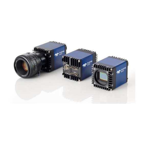
The Falcon2 Cameras Description The Falcon2 4M, 8M, and 12M are Teledyne DALSA’s new generation of area scan cameras. The Falcon2 cameras incorporate large resolutions and increased frame rates, enabling high speed image capture with superb spatial resolution. Features such as global shutter and improved image quality make the Falcon2 cameras the camera of choice in applications where throughput, resolution, and dynamic range matter. -
Page 8: Part Numbers And Software Requirements
Part Numbers and Software Requirements The camera is available in the following configurations. Table 1: Camera Models Overview Model Number Description FA-80-12M1H-XX-R 12M pixel monochrome Camera Link. FA-81-12M1H-XX-R 12M pixel color Camera Link. FA-80-8M100-XX-R 8M pixel monochrome Camera Link. FA-81-8M100-XX-R 8M pixel color Camera Link. -
Page 9: Camera Performance Specifications
Camera Performance Specifications Table 3: Camera Performance Specifications Specifications Performance Resolution 4 : 3 aspect ratio: 12M—4096 (H) x 3072 (V) 8M—3328 (H) x 2502 (V) 4M—2432 (H) x 1728 (V) 1 : 1 aspect ratio: 8M—2816 (H) x 2816 (V) 4M—2048 (H) x 2048 (V) Pixel Rate 8 x 76 MHz or 10 x 76 MHz... -
Page 10: Certifications
1728 * Sensor bits per pixel An online frame rate calculator is available from the Falcon2 product page on the Teledyne DALSA site, here. Certifications Compliance EN 55011, CISPR 11, EN 55022, CISPR 22, FCC Part 15, and ICES-003 Class A Emissions Requirements. -
Page 11: Supported Industry Standards
Supported Industry Standards GenICam The cameras are GenICam™ compliant. The cameras implement a superset of the GenICam Standard Features Naming Convention specification V1.5. This description takes the form of an XML device description file complying with the syntax defined by the GenApi module of the GenICam specification. -
Page 12: Responsivity & Quantum Efficiency
Responsivity & Quantum Efficiency The responsivity graph describes the camera’s response to different wavelengths of light (excluding lens and light source characteristics). Figure 1: Falcon2 Monochrome 8M Spectral Responsivity Note: 8 Taps, 10 bits Camera Link, FFC on, 24 fps (except 400 nm, measured at 10 fps), ND 0.3 filtered light 12 •... - Page 13 Figure 2: Falcon2 Color 12M (4096x3072) Spectral Responsivity GreenRed GreenBlue Blue 400 440 480 520 560 600 640 680 720 760 800 840 880 Wavelength (nm) Note: 8 taps 10 bits Camera link, 9 Bit sensor digitization, FFC on, color corrected, 4 fps (except for color red, which used different frame rate at wavelength 560nm and below: 400~480nm was done at 1.8 fps, 500 nm was done at 4 fps and 520~560), BG 38 filtered light The Falcon2 Cameras...
- Page 14 Figure 3: Quantum Efficiency 60.0% 50.0% 40.0% [INSERT QE GRAPH HERE] CM28M CM25M Effective Spectral Quantum Efficiency 30.0% 20.0% 10.0% 0.0% Wavelength (nm) 14 • The Falcon2 Cameras...
-
Page 15: Sensor Cosmetic Specifications
Sensor Cosmetic Specifications The following table lists the current cosmetic specifications for the Teledyne DALSA sensor used in the Falcon2 series. Feature / Unit Notes Specification Dark Pixel Definition - > 500 4 frame average absolute output level Dark Pixel Count Light Pixel Definition - ±... -
Page 16: Sensor Block Diagram And Pixel Readout
Figure 4: 8 Tap Camera Link Configuration Sensor Block Diagram. 8M Color Camera at Aspect Ratio 4 : 3. Notes: As viewed looking at the front of the camera without a lens. (The Teledyne DALSA • logo on the side of the case will be right-side up.) The monochrome camera uses the same layout, but without the color filters. -
Page 17: Mechanicals
Mechanicals Figure 5: Camera Mechanical [ADD MECHANICAL PDF HERE] The Falcon2 Cameras • 17... -
Page 18: Software And Hardware Setup
GenCP compliant applications to know the camera’s capabilities immediately after connection. Installing SaperaLT gives you access to the CamExpert GUI, a GenCP compliant application. The SaperaLT software is available from the Falcon2 page of the Teledyne DALSA Web site, here. 2. Connect Camera Link Cables and Power Connect the Camera Link cables from the camera to the computer. -
Page 19: Step 1. Install And Configure The Frame Grabber And Software
At this point you will be ready to start operating the camera in order to acquire images, set camera functions, and save settings. Step 1. Install and configure the frame grabber and Software Install Frame Grabber Install a compatible Camera link frame grabber according to the manufacturer’s description. We recommend the X64 Xcelera-CL PX8 frame grabber or equivalent, described in detail on the teledynedalsa.com site here. -
Page 20: Power Connector
Static electricity can damage electronic components. It’s critical that you discharge any static electrical charge by touching a grounded surface, such as the metal computer chassis, before performing handling the camera hardware. Power Connector WARNING: It is extremely important that you apply the appropriate voltages to your camera. -
Page 21: Camera Link Data Connector
Keep leads as short as possible in order to reduce voltage drop. • Use high-quality linear supplies in order to minimize noise. • Note: If your power supply does not meet these requirements, then the camera performance specifications are not guaranteed. Camera Link Data Connector The cameras use two mini-Camera Link SDR-26 cables transmitting the Camera Link Full or Extended configuration. -
Page 22: Step 3. Establish Communication With The Camera
Step 3. Establish Communication with the Camera Power on the camera Turn on the camera’s power supply. You may have to wait up to 60 seconds for the camera to warm up and prepare itself for operation. The camera must boot fully before it will be recognized by the GUI—the LED turns green once the camera is ready. - Page 23 Figure 8: Two CamExpert windows shown: one connected to the frame grabber and one connected to the camera At this point you are ready to start operating the camera in order to acquire images, set camera functions, and save settings. Software and Hardware Setup •...
-
Page 24: Camera Operation
In this category, the number of features shown is identical whether the view is Beginner, Expert, or Guru. Features listed in the description table but tagged as Invisible are usually for Teledyne DALSA or third party software usage—and not typically required by end-user applications. - Page 25 Name Space SFNC Firmware Release Visibility Beginner Access Read-only Type String Values Teledyne DALSA Name DeviceModelName Display Name [Device] Model Name Name Space Standard Firmware Release Visibility Beginner Access Read-only Type String Values e.g. ― FA_80_8M100_01 Name DeviceFamilyName Display Name...
- Page 26 Type Enumeration Values Sensor - temperature sensor on sensor board Mainboard- temperature sensor on main board Notes Changing this value will force the camera to read and update the DeviceTemperature Feature. Name DeviceTemperature Display Name Temperature ( C ) Name Space Standard Firmware Release Visibility...
-
Page 27: Factory Settings
DFNC Firmware Release Visibility Invisible Access Read-only Type Integer Values Notes Major revision of Dalsa Feature Naming Convention which was used to create the device’s XML. Name deviceDFNCVersionMajor Display Name DFNC Major revision Name Space DFNC Firmware Release Visibility Invisible... -
Page 28: Saving And Restoring Camera Settings
Flat field coefficients enabled (calibrated in internal exposure mode, non-concurrent • readout and integration). Internal exposure mode (internal frame rate and exposure time). • Maximum frame rate and exposure time. • Extended Camera Link mode 10 taps, 8 bits, 76 MHz pixel rate. •... -
Page 29: Acquisition And Transfer Control Category
4. Set the default selector to UserSet1. 5. Save User Set 1. 6. Power cycle the camera. 7. Reconnect to the camera through CamExpert. 8. The FFC mode will be Off when it should be ActiveAll. Acquisition and Transfer Control Category This category contains invisible registers that support feature streaming. - Page 30 Name DeviceRegistersStreamingEnd Display Name Device Registers Streaming End Name Space SFNC Firmware Release Visibility Invisible Access Read-Write Type Command Notes Announces end of registers streaming and performs validation for registers consistency before activating them. Name DeviceRegistersPersistenceStart Display Name Device Registers Persistence Start Name Space SFNC Firmware Release...
-
Page 31: Sensor Control Category
Parameters in black are user set in CamExpert or programmable via an imaging application. Features listed in the description table but tagged as Invisible are usually for Teledyne DALSA or third party software usage—not typically needed by end user applications. - Page 32 Access Read-only Type Enumeration Values "Monochrome" for monochrome camera "CFA Bayer Sensor" for color camera (CFA = Color filter array) Name SensorWidth Display Name Sensor Width Name Space Standard Firmware Release Visibility Beginner Access Read-only Type Integer Values See Table 9 for maximum width for given model and aspect ratios Notes The maximum width (in pixels) of the AOI for the given aspect ratio (sensorResolutionAspectRatio)
- Page 33 Name ExposureMode Display Name Exposure Mode Name Space Standard Firmware Release Visibility Beginner Access Read-Write Type Enumeration Values Timed - The exposure duration time is set using the ExposureTime feature TriggerWidth - Uses the width of the current Frame trigger signal pulse to control the exposure duration (see TriggerSource feature).
- Page 34 Name Space SFNC Firmware Release Visibility Beginner Access Read-Write (Read-only when TriggerMode equals On) Type Float Values 0.001x to 8x (for digital), 1x to ~ 1.4x (for analog gain) Notes Specifies the gain in terms of a multiplication factor. For the color cameras, the camera stores color gain values for each pixelSizeInput value. For example, the red gain for 8 bpp can be different than the red gain for 10 bpp.
- Page 35 Notes Specifies the size of the pixel that is output by the sensor. Name sensorResolutionAspectRatio Display Name Sensor Aspect Ratio Name Space DFNC Firmware Release Visibility Beginner Access Read-Write Type Enumeration Values Aspect4to3 [4:3 Aspect Ratio] - The aspect ratio (x:y) of the sensor is 4:3. Aspect1to1 [1:1 Aspect Ratio] - The aspect ratio (x:y) of the sensor is 1:1.
- Page 36 Name sensorFirstFrameClearMode Display Name Clear first frame Name Space Custom Firmware Release Visibility Guru Access Read-Write Type Enumeration Values Off – No Extra First Frame Clear On – Extra first frame clear applied Notes This feature controls whether or not to boost the first frame clear function. The first frame clear is designed to reduce charge that accumulates on the sensor when the camera is idle.
-
Page 37: Gain And Black Level Control Details
Hidden register to support feature streaming. Gain and Black Level Control Details The Falcon2 series of cameras provide gain and black level adjustments. Depending on the model of camera adjustments are available at the sensor as an analog variable and / or in the digital domain. -
Page 38: Set Aspect Ratio
Background Subtract is a digital number that is used to reduce the baseline pixel • value. When combined with the system gain, this value is used to increase contrast in the final output. See the BlackLevel register’s DigitalAll2 [Digital After FFC] option. System (Digital) Gain is expressed as a multiplication factor applied after the Analog •... - Page 39 Internally Programmable Frame Rate and Internally Programmable Exposure Time (Default) Frame rate is the dominant factor when adjusting the frame rate or exposure time. When setting the frame rate, exposure time will decrease, if necessary, to accommodate the new frame rate. When adjusting the exposure time the range is limited by the frame rate. Note: The camera will not set frame periods shorter than the readout period.
-
Page 40: Exposure Time
Figure 13: External Frame Rate and External Exposure Time (Trigger Width) External Frame Rate, Programmable Exposure Time In this mode, the frame rate is set externally with the falling edge of EXSYNC generating the rising edge of a programmable exposure time. Camera Features: TriggerMode = On •... -
Page 41: Internal Frame Rate
(input pixel size). In addition, an online frame rate calculator is available from the Falcon2 product page on the Teledyne DALSA site, here. Table 9 Maximum Frame rate for 10 Tap Cameralink Configuration... -
Page 42: I ∕ O Control Category
Parameters in black are user set in CamExpert or programmable via an imaging application. Features listed in the description table but tagged as Invisible are usually for Teledyne DALSA or third party software usage—not typically needed by end user applications. Figure 15: I / O Category in CamExpert 42 •... -
Page 43: Event Control Feature Descriptions
The following table describes these parameters along with their view attribute and minimum camera firmware version required. Additionally, the table will indicate which parameter is a member of the DALSA Features Naming Convention (DFNC), versus the GenICam Standard Features Naming Convention... - Page 44 Notes Generate an internal trigger. Available when the trigger mode is enabled and the trigger source is equal to ‘Software’. Name TriggerOverlap Display Name Trigger Overlap Name Space SFNC Firmware Release Visibility Beginner Access Read-Only Type Enumeration Values Off – No Trigger overlap is allowed. Notes Specify the type of trigger overlap permitted with the previous frame.
- Page 45 Visibility Beginner Access Read-Only Type Enumeration Values Input 1, Input 2, Input 3, Input 4, Input 5, Input 6 Output 1, Output 2 Notes Description of the physical pin associate with the logical line. Name linePinAssociation Display Name Line Pinout Name Space DFNC Firmware Release...
- Page 46 Name Space SFNC Firmware Release Visibility Beginner Access Read-Write Type Boolean Values True – invert signal False – don’t invert signal Notes Controls whether to invert the selected input or output line signal. Name LineStatus Display Name Line Status Name Space SFNC Firmware Release Visibility...
- Page 47 Values Off – The output line is open SoftwareControlled – The value of the output line is determined by outputLineValue, outputLineSoftwareLatchControl and/or outputLineSoftwareCmd. PulseOnStartofInternalEXSYNC – Generate pulse on start of EXSYNC signal to sensor PulseOnEndOfInternalEXSYNC – Generate pulse on end of EXSYNC signal to sensor PulseOnStartofExposure –...
- Page 48 Name outputLineSoftwareLatchControl Display Name Output Line Software Latch Control Name Space DFNC Firmware Release Visibility Beginner Access Read-Write Type Enumeration Values changes to the output line value are applied immediately. Off – changes to the output line value are applied when the Output Line Latch –...
- Page 49 Name externalControlledGainMode Display Name External Gain Mode Name Space Custom Firmware Release Visibility Beginner Access Read-Write Type Enumeration Values Off – disable external line controlled gain On – enable external line controlled gain Notes Enables and disables the gain that is controlled by the digital input lines Name externalControlledGainLineActivation Display Name...
-
Page 50: Trigger Modes
Notes Specifies the most and least significant bits that define the externally controlled gain factor. Gain Factor Invisible Features Name streamingGPIOLineSelector Name Space Custom Firmware Release Visibility Invisible Notes Internal use. To implement feature streaming. Name streamingGPIO Name Space Custom Firmware Release Visibility Invisible... -
Page 51: Cameralink Control Lines
Figure 16 I/O Module Block Diagram CameraLink Control Lines Falcon2 can use the four CameraLink control lines to trigger frames or output pulses. These signals are located in the CameraLink 1 cable (See Appendix A: Camera Link) and bypass the Line detection level. Opto-coupled Inputs Falcon2 provides two sets of Opto-isolated input signals. -
Page 52: Opto-Coupled Outputs
CamExpert or programmable via an imaging application. Note that the features listed in the description table but tagged as Invisible are usually for Teledyne DALSA Support or third party software usage—and not typically required by end- user applications. - Page 53 Figure 19 Advanced Processing Control Camera Operation • 53...
-
Page 54: Advanced Processing Control Feature Descriptions
Advanced Processing Control Feature Descriptions The following table describes these parameters along with their view attribute and the minimum camera firmware version required. Name flatfieldCorrectionMode Display Name Flat field Correction Mode Name Space DFNC Firmware Release Visibility Beginner Access Read/Write Type Enumeration Values... - Page 55 Name flatfieldCorrectionType Display Name Correction Type Name Space DFNC Firmware Release Visibility Expert Access Read Only Type Enumeration Values AreaBase Notes Flatfield correction is based on an entire image (array). Name flatfieldCorrectionCurrentActiveSet Display Name Current Active Set Name Space DFNC Firmware Release Visibility Expert...
- Page 56 Type Float Values 1 to 2 (when flatfieldCorrectionGainMode = HighGain). 1 to 1.5 (when flatfieldCorrectionGainMode = HighResolution). Notes Sets the gain to apply to the currently selected pixel. Name flatfieldCorrectionOffset Display Name Pixel Offset(FPN) Name Space DFNC Firmware Release Visibility Beginner Access Read-Write when in Calibration Mode...
- Page 57 Type Float Units Values 0 to 100 Notes Sets the target pixel value for the gain (PRNU) calibration. It is specified as a percentage of the output range (for example, 1023 DN for 10 bits). Name flatfieldCalibrationPRNU Display Name Gain(PRNU) Calibration Name Space DFNC Firmware Release...
- Page 58 Name Space DFNC Firmware Release Visibility Expert Access Read-Write when in Calibration Mode Type Command Notes Copies the currently selected flat field coefficients in the Active Set. Name flatfieldCorrectionPixelReplacementThreshold Display Name Pixel Replacement Threshold Name Space Custom Firmware Release Visibility Guru Access Read-Write...
- Page 59 Values Method1 (Average/Copy Adjacent) – the algorithm consists of averaging the adjacent pixels when replacing a single defect and copying the nearest pixel when replacing two consecutive defects or a defect at the beginning or end of a line, i.e. A= pixel A B= pixel B X= defect...
- Page 60 Name flatfieldCalibrationPixelReplacementGainThreshold Display Name Pixel Replacement Calibration Threshold Name Space Custom Firmware Release Visibility Guru Access Read-Write when flatfieldCorrectionMode = "Calibration" Type Float Values 1.5 to 9 (when flatfieldCalibrationGainMode = High Resolution) 2 to 17 (when flatfieldCalibrationGainMode = High Gain) Notes Specifies the gain (PRNU) value, above which the pixel is marked as defective.
- Page 61 Name flatfieldCalibrationUncorrectableDeadPixels Display Name Uncorrectable Dead Pixels Name Space Custom Firmware Release Visibility Guru Access Read Type Integer Values 0 to (Width * Height) Notes Reports the number of dead pixels (i.e. with uncorrectable PRNU) that cannot be replaced. The camera cannot correct any more than two horizontally adjacent pixels (i.e. only the pixels on the ends of a horizontal cluster will get corrected) .
- Page 62 Name flatfieldCalculatePixelStatistics Display Name Calculate Pixel Statistics Name Space Custom Firmware Release Visibility Guru Access Read-Write Type Command Values Notes This command calculates the pixel statistics. Name defectivePixelDetectionAlgorithmSelector Display Name Dynamic Replacement Algorithm Name Space Custom Firmware Release Visibility Expert Access Read-Write Type...
- Page 63 Name Space Custom Firmware Release Visibility Guru Access Read-Write Type Integer Values -127 to 127 Notes Retrieves and sets the simple feed through correction coefficient. Name feedThroughCorrectionMode Display Name Feed Through Correction Apply Firmware Release Name Space Custom Visibility Guru Access Read-Write Type...
- Page 64 Firmware Release Visibility Invisible Access Read Only Type Integer Values Notes The camera uses this value to calculate the FFC gain factor. Used for Sapera FFC Support. This is equivalent to the high gain setting with the in-camera calibration. In other words when you calibrate the camera in the host, it can only be a High Gain PRNU calibration.
- Page 65 Type Integer Values Notes The maximum valid gain coefficient value. Used for Sapera FFC Support. Name flatfieldAlgorithmGainMin Name Space DFNC Firmware Release Visibility Invisible Access Read Only Type Integer Values Notes The minimum valid gain coefficient value. Used for Sapera FFC Support. Name complexFeedThroughCoeff1, complexFeedThroughCoeff2, complexFeedThroughCoeff3...
-
Page 66: Flat Field Correction And Defective Pixel Detection Overview
Flat Field Correction and Defective Pixel Detection Overview The Flat Field correction function consists of using two coefficients per pixel which correct the gain and offset of the corresponding pixel. These corrections compensate for the Photo- response Non-uniformity (PRNU) and Fixed Pattern noise (FPN) attributes unique to each camera sensor. - Page 67 GainDivisor is either 512 or 1024 depending on whether the camera was calibrated • in High resolution or high gain mode. See flatfieldCalibrationGainMode and flatfieldCorrectionGainMode. General Notes on FFC calibration The camera comes calibrated with three factory sets, one for each sensor bit depth. These sets switch automatically when the user changes pixelSizeInput.
-
Page 68: How To Do An Ffc Setup In The Camera
Figure 22. Spectral distribution of light source used during calibration of color cameras only. This corresponds roughly to a 5200 K color temperature. How to do an FFC Setup in the Camera CamExpert has a default timeout of 20 seconds per command, which is too short for the FFC calibration to run fully. - Page 69 If the camera is run at exposure time that is significantly higher than the calibration exposure, an additional Pixel Replacement Calibration may be require The gain (PRNU) calibration is performed next to determine the multiplication factors required to bring each pixel to the required value (target) for flat, white output. For the monochrome cameras, the target is determined by the user (See flatfieldCalibrationTarget).
-
Page 70: How To Do A Ffc Setup Via Sapera Camexpert
2. The camera is placed in the dark and FPN Calibration is run. 3. With FPN correction on the sensor is illuminated (Light Source: Broadband Quartz Halogen, 3250 K, with a 750 nm cut-off filter) with a light level of 26.4 µW/cm BPP). - Page 71 Close the camera lens iris and cover the lens with a lens cap. Using CamExpert, click on the grab button and then the histogram button. The following figure shows a typical histogram for a Falcon2 grabbing a very dark image. Figure 24 CamExpert histogram of a dark scan (8 bit output) Important: In this example, the average pixel value for the frame is close to black.
- Page 72 Important: In this example, the average pixel value for the frame is bright gray. Also note that sensors may show a much higher maximum or a much lower minimum pixel value due to one or more "hot or dead pixels". The sensor specification accounts for a small number of hot, stuck, or dead pixels (pixels that do not react to light over the full dynamic range specified for that sensor).
- Page 73 1. Click on the Advanced Setting button to change the default number of frames averaged for each calibration step. The default value is 10 frames (as performed by CamExpert). Camera Operation • 73...
- Page 74 2. Setup the camera to capture a uniform dark image. Black paper with no illumination and the camera lens’ iris closed to minimum can provide such a dark image. Or cover the lens with a black lens cap. 3. Click on Acquire Black Image. The flat field calibration tool will grab video frames, analyze the pixel gray level spread, and present the statistics.
-
Page 75: Defective Pixel Detection And Replacement
6. Click on Save. The flat field correction data is saved as a TIF image with a file name of your choice (suggestions are the camera name and its serial number). Using Flat Field Correction When using CamExpert, from the menu bar enable Flat Field correction (Pre-Processing > Flat Field Correction >... - Page 76 The pixel replacement calibration algorithm adds the new found hot pixels to the pixel defect map and must be run after an offset calibration. If the difference between the average pixel value and the stored offset value (FPN coefficient) is greater than the calibration threshold (i.e.
-
Page 77: Image Format Controls Category
Parameters in black are user set in CamExpert or programmable via an imaging application. Features listed in the description table but tagged as Invisible are usually for Teledyne DALSA Support or third party software usage—not typically required by end user applications. - Page 78 Name Space SFNC Firmware Release Visibility Beginner Access Read-Write Type Integer Values Minimum: 2 Maximum: SensorHeight - OffsetY Increment: 2 Name OffsetX Display Name Offset X Name Space SFNC Firmware Release Visibility Beginner Access Read-Write Type Integer Values Minimum: 0 Maximum: SensorWidth –...
- Page 79 Name PixelCoding Display Name Pixel Color Filter Name Space SFNC Firmware Release Visibility Beginner Access Read-Only Type Enumeration Values Mono – Monochrome pixel data Notes Output image pixel coding format of the sensor. Name PixelSize Display Name Pixel Color Filter Name Space SFNC Firmware Release...
- Page 80 Values Active – Multiple area of interest mode is active Off – Multiple area of interest mode is not active. Use single AOI. Notes [Preliminary] Enables or disables the multiple area of interest mode Name multipleAOICount Display Name Multiple AOI Count Name Space Custom Firmware Release...
-
Page 81: Test Patterns
Firmware Release Visibility Guru Access Read-Write when multipleAOIMode is Active Type Integer Values Minimum: 0 Maximum: (SensorHeight – multipleAOIWidth) Increment: 2 Notes Preliminary] Specifies the horizontal offset for all of the areas of interest. Name multipleAOIOffsetY Display Name [Mulitple] AOI Offset Y Name Space Custom Firmware Release... - Page 82 Grey Horizontal Ramp: Image is filled horizontally with an image that goes from the darkest possible value to the brightest. The ramp repeats every 1024 horizontal pixels. Figure 28 Gray Horizontal Ramp (not to scale) Grey Vertical Ramp: Image is filled vertically with an image that goes from the darkest possible value to the brightest.
- Page 83 PRNU: This test pattern is the sum of 2*(FPN diagonal ramp) + testImageStaticValue. This test pattern can be used to test PRNU correction. SensorStaticPattern1: This test pattern originates in the sensor and consists of two alternating vertical lines. The value depends on the PixelFormat and pixelSizeInput. SensorDynamicPattern1: This test pattern originates in the sensor and consists of two interleaved vertical ramps.
-
Page 84: Multiple Aoi Mode
Multiple AOI Mode Use the Multiple AOI commands to define multiple areas of interest. Once defined, each of the AOIs shares a common width and x-offset value. That is, all the allowable windows you define will have the same pixel width and the same starting coordinate (x-offset value). Within these defined parameters you are free to set the height and y-offset values, including overlapping height values. -
Page 85: Camera Link Transport Layer Category
Parameters in black are user set in CamExpert or programmable via an imaging application. Features listed in the description table but tagged as Invisible are usually for Teledyne DALSA Support or third party software usage—and are not typically required by end user applications. -
Page 86: Camera Link Transport Layer Feature Description
The following table describes the category’s parameters along with their view attribute and minimum camera firmware version required. Additionally the table will indicate which parameter is a member of the DALSA Features Naming Convention (DFNC), GenICam Standard Features Naming Convention, or a custom camera feature. - Page 87 Some third party frame grabbers require that the FVAL and the first LVAL are separated by a given amount of time. This feature sets the number of clocks to add to the FVAL transition before the LVAL goes high. This feature is not necessary for Teledyne DALSA frame grabbers. Name clSmoothLineValidTiming...
- Page 88 Name Space SFNC Firmware Release Visibility Beginner Access Read-Write Type Enumeration Values Geometry_1X8_1Y - 8 tap area scan, with 1 zone in X with 8 alternating taps & 1 zone in Tap 1 starts with pixel coordinate (1,1), extending to the image width -1 and height, using a step of 8 (that is x = 1, 9, 17,…).
-
Page 89: Serial Port Control Category
The following table describes the category’s parameters along with their view attribute and minimum camera firmware version required. Additionally the table will indicate which parameter is a member of the DALSA Features Naming Convention (DFNC), GenICam Standard Features Naming Convention or a custom camera feature. -
Page 90: Automatic Serial Speed Detection
determined. Name deviceSerialPortDataSize Display Name Serial Port Data Size Name Space DFNC Firmware Release Visibility Beginner Access Read-Only Type Enumeration Values bcp8 -8 bits per character Notes The number of bits that transmit a single character Name deviceSerialPortParity Display Name Serial Port Parity Name Space DFNC... - Page 91 Figure 34 File Access Control Category in CamExpert Name FileSelector Display Name File Selector Name Space SFNC Firmware Release Visibility Beginner Access Read-Write Type Enumeration Values Firmware: [Write-Only] Writing a new firmware here will update the camera. UserFlatfieldCoefficients1: Previously saved flat field coefficients (i.e. gain and offset). UserFlatfieldCoefficients2: Previously saved flat field coefficients (i.e.
- Page 92 Name FileOperationExecute Display Name File Operation Execute Name Space SFNC Firmware Release Visibility Beginner Access Read-Write Type Command Notes Executes the operation selected by File Operation Selector on the selected file. Name FileOpenMode Display Name File Open Mode Name Space SFNC Firmware Release Visibility...
- Page 93 Name Space SFNC Firmware Release Visibility Beginner Access Read-Only Type Enumeration Values Success: The last file operation has completed successfully. Failure:The last file operation has completed unsuccessfully for an unknown reason. FileUnavailable:The last file operation has completed unsuccessfully because the file is currently unavailable.
-
Page 94: File Access Via The Camexpert Tool
File Access via the CamExpert Tool 1. Click on the “Setting…” button to show the file selection menu. Figure 35 Initial File Access Control Dialog 2. From the Type drop menu, select the file type that will be uploaded to the camera. 3. -
Page 95: Appendix A: Camera Link
Recommended Cables We recommend the use of high-quality mini-CL cables. Teledyne DALSA has 3 meter and 5 meter cables available as accessories. Contact Customer Support. Data Connector: Camera Link The camera uses two mini-Camera Link SDR-26 cables transmitting the Camera Link Full or Extended configuration. - Page 96 Figure 36: SDR-26 Mini Camera Link Connector Data 2 Control / Data 1 Camera Right Angle Channel Link Camera Right Angle Channel Link Connector Frame Grabber Signal Connector Frame Grabber Signal Connector Connector inner shield inner shield inner shield inner shield Yclk- Xclk- Yclk+...
-
Page 97: Full Configuration
Full Configuration 8 taps 8 bits Camera link Full configuration Connector 1: Channel link X Connector 2: Channel link Y Connector 3: Channel link Z Camera/Frame Camera/Frame Camera/Frame Grabber Pin Bit Name Grabber Pin Bit Name Grabber Pin Bit Name Tx0/Rx0 D0(0) Tx0/Rx0... -
Page 98: Extended Configurations
Extended Configurations 10 taps 8 bits Camera link Extended configuration Connector 1: Channel link X Connector 1: Channel link Y Connector 1: Channel link Z Camera/Frame Camera/Frame Camera/Frame Grabber Pin Bit Name Grabber Pin Bit Name Grabber Pin Bit Name Tx0/Rx0 D0(0) Tx0/Rx0... - Page 99 8 taps 10 bits Camera link Extended configuration Connector 1: Channel link X Connector 1: Channel link Y Connector 1: Channel link Z Camera/Frame Camera/Frame Camera/Frame Grabber Pin Bit Name Grabber Pin Bit Name Grabber Pin Bit Name Tx0/Rx0 D0(2) Tx0/Rx0 D3(2) Tx0/Rx0...
-
Page 100: Appendix B: Camera, Frame Grabber Communication
Teledyne DALSA Camera Link cameras support the GenCP CameraLink standards. To configure Teledyne DALSA GenCP Camera Link Cameras: 1. Install the Teledyne DALSA frame grabber in the host computer; refer to the hardware installation manual 2. Install Sapera LT and the Teledyne DALSA frame grabber driver. - Page 101 frame grabber parameters must be adjusted separately. 6. Modify the camera and frame grabber parameter settings as required, and test the image acquisition by clicking the Grab button. 7. Save the frame grabber configuration to a new *.ccf file. Appendix B: Camera, Frame Grabber Communication •...
-
Page 102: Appendix C: Cleaning The Sensor Window
Appendix C: Cleaning the Sensor Window Recommended Equipment • Glass cleaning station with microscope within clean room. 3M ionized air gun 980 • (http://solutions.3mcanada.ca/wps/portal/3M/en_CA/WW2/Country/) Ionized air flood system, foot operated. • Swab (HUBY-340CA-003) • (http://www.cleancross.net/modules/xfsection/article.php?articleid=24) Single drop bottle (FD-2-ESD) • E2 (Eclipse optic cleaning system (www.photosol.com) •... -
Page 103: Appendix D: Internal Flat Field Calibration Algorithms
Appendix D: Internal Flat Field Calibration Algorithms The camera provides the user with the ability to perform a custom flat field calibration. This appendix gives details of the calibration algorithms. All calibration is performed on averaged image data to reduce noise. Offset (FPN) Calibration Offset calibration is performed when the sensor is not exposed to light. - Page 104 Subtract the previously calibrated offset values (FPN). Calculate the multiplication factor necessary to achieve the target value. The target value is calculated using flatfieldCalibrationTarget. See Figure 37. Target PRNU Multiplier Pixel Figure 37. Monochrome Flat Field Gain Calibration If the calculated gain is less than 1 then the number of clipped gain pixels (flatfieldCalibrationGainPixelsClipped) is incremented.
-
Page 105: Appendix E: Three Letter Commands
Appendix E: Three Letter Commands In addition to the GenICam interface, the Falcon2 camera supports the classic three letter command (TLC) interface. This method of controlling the camera may be preferable to customers with existing systems that use TLCs or who are using an operating system that is not supported by Sapera or GenICam. -
Page 106: Setting The Sapera's Com Port Mapping
6. An OK prompt should appear. NOTES: 1. Some GenICam Software automatically adjusts the baud rate so if you are not power cycling or resetting the camera then you will need to determine the baud rate from the DeviceSerialPortBaudRate. 2. The Hyperterminal application is not available in the Windows 7 OS. The following alternative ASCII-interfaces have been tested and shown to work with this camera: TeraTerm: http://logmett.com/index.php?/download/tera-term-473-... -
Page 107: Getting Parameters (Gcp Or Get)
Getting Parameters (gcp or get) The gcp command provides a snapshot of all of the camera’s settings. It is a good place to start to get familiar with the camera’s capabilities and features. In addition to the gcp command, the get command provides a way to get the value associated with a given command (eg. - Page 108 Full Name area of interest - offset x Mnemonic Argument(s) offset 0 to (max width – width) in increments of 128 Max height determined by model and aspect ratio in increments of 128 GenICam OffsetX Release Notes The values will be rounded to the nearest increment. Changing the aspect ratio will change the values of the AOI Full Name calibrate fpn correction...
- Page 109 Full Name calibrate pixel replacement Mnemonic Argument(s) threshold Specifies the difference between offset(FPN) and average value(during pixel calibration), above which the pixel is marked as defective. GenICam flatfieldCalibrationPixelReplacement flatfieldCalibrationPixelReplacementOffsetThreshold Release Notes Only available when flat field mode is set to calibration ( i.e. ffm = CAL) May take several seconds to several minutes to complete depending on frame rate See Appendix D: Internal Flat Field Calibration Algorithms for more information.
- Page 110 Full Name flatfield display stats Mnemonic GenICam flatfieldCalculatePixelStatistics flatfieldCalibrationGainPixelsClipped flatfieldCalibrationDeadPixelsNotReplaced flatfieldCalibrationOffsetPixelsClipped flatfieldCalibrationUncorrectableDeadPixels flatfieldCalibrationDeadPixelsReplaced flatfieldCalibrationUncorrectableHotPixels flatfieldCalibrationHotPixelsReplaced Release Notes Displays flatfield statistics. e.g. OK>fds Hot Pixels Uncorrectable Hot Pixels : 0 Dead Pixels Replaced : 19 Uncorrectable Dead Pixels: 123 Dead Pixels Not Replaced : 0 Offset Pixels Clipped Gain Pixels Clipped OK>^...
- Page 111 Full Name get camera model Mnemonic GenICam DeviceModelName Release Notes Returns a string containing the model name Full Name get camera parameters Mnemonic Release Appendix E: Three Letter Commands • 111...
- Page 112 Notes Returns a snap shot of the camera’s settings e.g. OK>gcp *** Camera Settings *** Manufacturer Name:Teledyne DALSA Model Name: FA_81_8M100_01 Family Name: Falcon2 Sensor Type: Bayer Color Filter Array Device Version: 255.101.591 Manufacturer Info: Serial Number: C123456 User Defined Name:myCamera...
- Page 113 Full Name put camera in genicam mode Mnemonic Release Notes The camera returns an OK> prompt then switches into GenICam mode. Full Name get values Mnemonic Argument(s) command String containing a command with a value associated with it(e.g. ssf, ffm, etc.) Release Notes The command does not return the units(e.g.
- Page 114 Full Name single command help Mnemonic Argument(s) command A string containing the command for which help is requested. Notes This may supply more information than the h command e.g. OK>? usd usd default user set N|F|1|2|3|4 Arg 1: N:Nothing F:Factory 1:User Set 1 2:User Set 2 3:User Set 3...
- Page 115 Full Name reset camera Mnemonic GenICam DeviceReset Release Notes After sending this command, you will need to put the camera back into three letter command mode because the camera boots in GenICam mode at 9600 baud. Full Name set analog course gain Mnemonic Argument(s) Gain...
- Page 116 Full Name set color gain Mnemonic Argument(s) color R|GR|GB|B gain 0.001~7.999 GenICam GainSelector = DigitalRed, DigitalBlue, DigitalGreenBlue, DigitalGreenRed Gain Release Notes Gain is express as a mulitplcation factor in increments of 1/1024. See processing chain for more information Full Name set line detection level Mnemonic Argument(s)
- Page 117 Full Name set input pixel size Mnemonic Argument(s) bits per pixel 8-10 GenICam pixelSizeInput Release Notes Color gain and factory ffc is dependant on this feature Full Name set input debouncing Mnemonic Argument(s) inputLine L1: general purpose input 1 L2: general purpose input 2 CC1: cameralink control line 1 CC2: cameralink control line 2 CC3: cameralink control line 3...
- Page 118 Full Name set output line source Mnemonic Argument(s) line L3: general purpose output 1 L4: general purpose output 2 source 0:Start Internal ExSync 1:Start Exposure 2:End Exposure 3:Strt Readout 4:End Readout 5:End Internal EXSYNC 6:Start Line Active 7:GP Input 1 8:GP Input 2 9:CC1 10:CC2...
- Page 119 Full Name set background subtract Mnemonic Argument(s) offset 0 to 1023 [DN] GenICam BlackLevelSelector = DigitalAll2 BlackLevel Release Notes See processing chain for more information Full Name set sync frequency Mnemonic Argument(s) frequency 1 to max frame rate [Hz] Max Frame rate determined by AOI, pixel size, number of camera link taps etc.
- Page 120 Full Name set trigger mode Mnemonic Argument(s) Mode i:Internal e:External GenICam TriggerMode Release Notes Full Name set trigger source Mnemonic Argument(s) Source L1: general purpose input 1 L2: general purpose input 2 CC1: cameralink control line 1 CC2: cameralink control line 2 CC3: cameralink control line 3 CC4: cameralink control line 4 S: Software...
- Page 121 Full Name verify temperature Mnemonic Argument(s) Sensor C:CPU Board S:Sensor Board GenICam DeviceTemperatureSelector DeviceTemperature Release Notes Full Name default user set Mnemonic Argument(s) set name N: Use default settings F: Factory Set 1: User Set 1 2: User Set 2 3: User Set 3 4: User Set 4 GenICam...
-
Page 122: Emc Declaration Of Conformity
FCC Part 15 Immunity to disturbances: EN55024 (1998) EN 61326-1 (2006) Place of Issue Waterloo, ON, CANADA Date of Issue June 1, 2011 Name and Signature of Hank Helmond authorized person Quality Manager, Teledyne DALSA Corp. 122 • EMC Declaration of Conformity... -
Page 123: Revision History
Revision History Revision Change Description Date Initial (Preliminary) release 11-Nov-11 Extensive revisions made throughout the manual in preparation for camera 03-Feb-12 production and general release. -Additional commands added. 17-Apr-13 -Color description and supporting technical content added. -Extensive revisions made throughout the Camera Operation section to add detail. -Power pinout illustration revised. -
Page 124: Index
Index set, 40 frame rates, 10 antiblooming, 9 grounding instructions, 20 overview, 22 block diagram sensor, 16 control, 42 Camera Link image acquisition, 38 cables, 95 Input / Output input signals, 21 control, 42 outputs, 21, 95 input/output, 19 Camera Link connector, 95 interface certifications, 10 mechanical, 9... - Page 125 graph, 14 settings factory, 27 setup overview, 18 software random noise, 9 required, 8 requirements specifications PC, 18 mechanical, 9 responsivity, 9 operating, 9, 10 graph, 12 performance, 9 revision history, 124 trigger modes, 50 safety, 6 Index • 125...
Need help?
Do you have a question about the Falcon2 Series and is the answer not in the manual?
Questions and answers