Table of Contents
Advertisement
Quick Links
Advertisement
Table of Contents

Related Manuals for Dalsa Falcon2 Series


Summary of Contents for Dalsa Falcon2 Series
- Page 1 Falcon2 User Manual www.teledynedalsa.com 03-032-20107-03...
- Page 2 Falcon2 4M, 8M, and 12M Camera User's Manual © 2013 Teled yne DALSA, Inc. All inform ation provid ed in this m anual is believed to be accurate and reliable. No responsibility is assum ed by Teled yne DALSA for its use. Teled yne DALSA reserves the right to make changes to this inform ation w ithout notice.
-
Page 3: Table Of Contents
4. Camera Operation ______________________________________________________________________________ 24 Camera Information Category ............................24 Camera Information Feature Descriptions...................... 24 Factory Settings ............................... 27 Saving and Restoring Camera Settings ......................28 Acquisition and Transfer Control Category ........................29 Sensor Control Category ..............................30 Teledyne DALSA 03-032-20107-03... - Page 4 Offset (FPN) Calibration ..............................100 Pixel Replacement Calibration ............................100 Gain (PRNU) Calibration ..............................100 Appendix E: Three Letter Commands ___________________________________________________________________ 102 Putting Camera In TLC Mode ............................102 Setting the Sapera’s COM Port Mapping ........................... 103 Getting Started .................................. 103 03-032-20107-03 Teledyne DALSA...
- Page 5 Falcon2 4M, 8M, and 12M Camera User's Manual The Help Command (h or ?) ........................... 103 Getting Parameters (gcp or get) ........................103 Commands ..................................104 EMC Declaration of Conformity _______________________________________________________________________ 117 Revision History _________________________________________________________________________________ 118 Index ________________________________________________________________________________________ 119 Teledyne DALSA 03-032-20107-03...
-
Page 6: System Precautions
The location of these p ixels w ill change w ith the angle of illu m ination. For inform ation on cleaning the sensor w ind ow , refer to the Cleaning the Sensor Wind ow section. 03-032-20107-03 Teledyne DALSA... -
Page 7: The Falcon2 Cameras
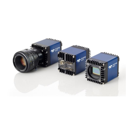
Camera Highlights The Falcon2 4M, 8M, and 12M are Teled yne DALSA‘s new generation of area scan cam eras. The Falcon2 cam eras incorp orate large resolu tions and increased fram e rates, enabling high sp eed im age cap tu re w ith su p erb sp atial resolu tion. - Page 8 Em bed d ed w ithin cam era Recom m end ed : Sap era LT, inclu d ing Cam Exp ert GUI Version 7.20 or later ap p lication and GenICam for Cam era Link im aging d river. 03-032-20107-03 Teledyne DALSA...
-
Page 9: Camera Performance Specifications
>1000 x Saturation DN rm s 1.7* Typical, FFC enabled PRN U DN rm s 2.6* Typical, FFC enabled Integral non-linearity < 2 % *12M, 10 bbp , 8 tap s / 10 bits Cam era Link Teledyne DALSA 03-032-20107-03... -
Page 10: Certifications
2048 2432 1728 * Sensor bits p er p ixel An online fram e rate calcu lator is available from the Falcon2 p rod u ct p age on the Teled yne DALSA site, here. Certifications Compliance EN 55011, CISPR 11, EN 55022, CISPR 22, FCC Part 15, and ICES-003 Class A Em issions Requirem ents. -
Page 11: Supported Industry Standards
Com m u nication betw een the fram e grabber and cam era occu rs u sing the GenCP m od u le (Generic Control Protocol). Further GenICam inform ation and d ocu m entation is available from the Eu rop ean Machine Vision Association‘s Web site (w w w .em va.org). Teledyne DALSA 03-032-20107-03... -
Page 12: Responsivity
The resp onsivity grap h d escribes the cam era‘s resp onse to d ifferent w avelengths of light (exclu d ing lens and light sou rce characteristics). Figure 1: Falcon2 Monochrome 8M Spectral Responsivity Note: 8 Taps, 10 bits Camera Link, FFC on, 24 fps (except 400 nm, measured at 10 fps), ND 0.3 filtered light 03-032-20107-03 Teledyne DALSA... - Page 13 Note: 8 taps 10 bits Camera link, 9 Bit sensor digitization, FFC on, color corrected, 4 fps (except for color red, which used different frame rate at wavelength 560nm and below: 400~480nm was done at 1.8 fps, 500 nm was done at 4 fps and 520~560), BG 38 filtered light Teledyne DALSA 03-032-20107-03...
- Page 14 Falcon2 4M, 8M, and 12M Camera User's Manual Figure 3: Quantum Efficiency 60.0% [IN SERT QE GRAPH HERE] 50.0% 40.0% CM28M CM25M Effective Spectral Quantum Efficiency 30.0% 20.0% 10.0% 0.0% Wavelength (nm) 03-032-20107-03 Teledyne DALSA...
-
Page 15: Sensor Cosmetic Specifications
Falcon2 4M, 8M, and 12M Camera User's Manual Sensor Cosmetic Specifications The follow ing table lists the cu rrent cosm etic sp ecifications for the Teled yne DALSA sensor u sed in the Falcon2 series. Feature / Unit Notes Specification Dark Pixel Definition - >... -
Page 16: Sensor Block Diagram And Pixel Readout
Figure 4: 8 Tap Camera Link Configuration Sensor Block Diagram. 8M Color Camera at Aspect Ratio 4 : 3. N otes: As view ed looking at the front of the cam era w ithout a lens. (The Teled yne DALSA logo on the sid e of the case w ill be right-sid e u p .) ... -
Page 17: Mechanicals
Falcon2 4M, 8M, and 12M Camera User's Manual Mechanicals [ADD MECH AN ICAL PDF H ERE] Figure 5: Camera Mechanical Teledyne DALSA 03-032-20107-03... -
Page 18: Software And Hardware Setup
To achieve best system p erform ance, the follow ing m inim u m requ irem ents are recom m end ed : H igh band w id th fram e grabber, e.g. DALSA PX8 Full Cam era link fram e grabber (Part # OR-X8CO- XPF00). -
Page 19: Step 1. Install And Configure The Frame Grabber And Software
Static electricity can d am age electronic com p onents. It‘s critical that you d ischarge any static electrical charge by tou ching a grou nd ed su rface, su ch as the m etal com p u ter chassis, before p erform ing hand ling the cam era hard w are. Teledyne DALSA 03-032-20107-03... -
Page 20: Power Connector
Keep lead s as short as p ossible in ord er to red u ce voltage d rop . Use high-qu ality linear su p p lies in ord er to m inim ize noise. If your power supply does not meet these requirements, then the camera performance specifications are not Note: guaranteed. 03-032-20107-03 Teledyne DALSA... -
Page 21: Camera Link Data Connector
At initial pow er up an d w hen acquisition is d isabled . This happens w hen changing a cam era feature that effects the im age output (e.g. aoi, bit d epth, etc.) Green solid Free-running acquisition Teledyne DALSA 03-032-20107-03... -
Page 22: Step 3. Establish Communication With The Camera
Do this by either (1) closing and reop ening the Cam Exp ert w ind ow , or (2) by going to ―Im age View er‖ in the ―Device‖ tab and selecting the cam era again. 03-032-20107-03 Teledyne DALSA... - Page 23 Figure 8: Two CamExpert windows shown: one connected to the frame grabber and one connected to the camera At this p oint you are read y to start op erating the cam era in ord er to acqu ire im ages, set cam era fu nctions, and save settings. Teledyne DALSA 03-032-20107-03...
-
Page 24: Camera Operation
. Ad d itionally, the N am e category ind icates w hich p aram eter is a m em ber of the DALSA Featu res N am ing Convention (u sing the tag DFNC), verses the GenICam Stand ard Featu res N am ing Convention (SFN C), and w hich is a cu stom cam era featu re. - Page 25 Firm w are Release Visibility Beginner Access Read -only Type String Values Teled yne DALSA N ame D eviceModelN ame Display N am e [Device] Model N ame N am e Sp ace Stand ard Firm w are Release Visibility...
- Page 26 Read -Write Type Com m and N otes Load s the cam era configuration set specified by the User Set Selector feature, from the cam era and m akes it active. Disabled w hen flatfieldCorrectionM ode = Calibration. 03-032-20107-03 Teledyne DALSA...
-
Page 27: Factory Settings
Invisible Access Read -only Type Integer Values Major revision of Dalsa Feature N am ing Convention w hich w as used to create the d evice‘s N otes XML. N ame deviceD FN CVersionMajor Display N am e D FN C Major revision... -
Page 28: Saving And Restoring Camera Settings
Save User Set 1. Pow er cycle the cam era. Reconnect to the cam era throu gh Cam Exp ert. The FFC m od e w ill be Off w hen it shou ld be A ctiveA ll. 03-032-20107-03 Teledyne DALSA... -
Page 29: Acquisition And Transfer Control Category
N am e Sp ace SFN C Firm w are Release Visibility Invisible Access Read -Write Type Com m and N otes Announces end of registers stream ing and perform s valid ation for regis ters consistency Teledyne DALSA 03-032-20107-03... -
Page 30: Sensor Control Category
Cam Exp ert or p rogram m able via an im aging ap p lication. Featu res listed in the d escrip tion table bu t tagged as Invisible are u su ally for Teled yne DALSA or third p arty softw are u sage—not typ ically need ed by end u ser ap p lications. -
Page 31: Sensor Control Feature Descriptions
The following table describes these parameters along with their view attribute and minimum camera firmware version required. Additionally the firmware column will indicate which parameter is a member of the DALSA Features Naming Convention (DFNC) verses the GenICam Standard Features Naming Convention (SFNC) or a custom camera feature. - Page 32 (see TriggerSource feature). Valid only w hen TriggerM ode is equal to On and TriggerSource is not Softw are Controlled . N otes Specifies the m ethod to control the exposure tim e of the cam era. 03-032-20107-03 Teledyne DALSA...
- Page 33 (i.e. PRN U) coefficients are calibrated in flat field correction. For both color and m onochrom e cam eras, the cam era stores an analog gain value for each pixelSizeInput value. Teledyne DALSA 03-032-20107-03...
- Page 34 Changing this value w ill cause the follow ing features to upd ate: - SensorW idth, SensorHeight - OffsetX , OffsetY , W idth, Height - multipleA OICount, multipleA OISelector, multipleA OIOffsetX , multipleA OIOffsetY , multipleA OIW idth, multipleA OIHeight 03-032-20107-03 Teledyne DALSA...
- Page 35 While this feature boosts functionality it also has the potential to introd uce ad d itional artefacts to the im age. This feature should only be used by experts and is norm ally set to Off. Changing this value m ay cause unexpected im age artefacts. Teledyne DALSA 03-032-20107-03...
-
Page 36: Gain And Black Level Control Details
Gain and Black Level Control Details The Falcon2 series of cam eras p rovid e gain and black level ad ju stm ents. Dep end ing on the m od el of cam era, ad ju stm ents are available at the sensor as an analog variable and / or in the d igital d om ain. The gain and black level controls can m ake sm all com p ensations to the acqu isition in situ ations w here lighting varies and the lens iris cannot be easily ad ju sted . - Page 37 Externally Controlled Gain the camera can be set up to apply a (2x, 4x, 8x) gain that is controlled by external input signals. For example, this allows the user to control digital gain (in factors of 2) on a frame- by-frame basis. See Teledyne DALSA 03-032-20107-03...
-
Page 38: Set Aspect Ratio
Note: The cam era w ill not set fram e p eriod s shorter than the read ou t p eriod . 03-032-20107-03 Teledyne DALSA... - Page 39 Camera Features: TriggerMode = On ExposureMode = Trigger Width User Exsync Exposure Time Exposure Time Readout Time Readout Time Frame Time Frame Time FVAL Figure 14: External Frame Rate and External Exposure Time (Trigger Width) Teledyne DALSA 03-032-20107-03...
-
Page 40: Exposure Time
8 bits p er p ixel 9 bits p er p ixel 10 bits p er p ixel Note: The maximum exposure time is dependent on the frame rate. To increase maximum exposure time, decrease the frame rate. 03-032-20107-03 Teledyne DALSA... -
Page 41: Internal Frame Rate
(inp u t p ixel size). In ad d ition, an online fram e rate calcu lator is available from the Falcon2 p rod u ct p age on the Teled yne DALSA site, here. Table 8 Maximum Frame rate for 10 Tap Cameralink Configuration... -
Page 42: I ∕ O Control Category
Parameters in black are user set in CamExpert or programmable via an imaging application. Features listed in the description table but tagged as Invisible are usually for Teledyne DALSA or third party software usage—not typically needed by end user applications. -
Page 43: Event Control Feature Descriptions
The following table describes these parameters along with their view attribute and minimum camera firmware version required. Additionally, the table will indicate which parameter is a member of the DALSA Features Naming Convention (DFN C), versu s the GenICam Stand ard Featu res N am ing Convention... - Page 44 Inp u t 1, Inp u t 2, Inp u t 3, Inp u t 4, Inp u t 5, Inp u t 6 Ou tp u t 1, Ou tp u t 2 N otes Description of the physical pin associate w ith the logical line . 03-032-20107-03 Teledyne DALSA...
- Page 45 SFN C Firm w are Release Visibility Beginner Access Read -Write Type Boolean True – invert signal Values False – d on‘t invert signal N otes Controls w hether to invert the selected input or output line signal. Teledyne DALSA 03-032-20107-03...
- Page 46 Selects w hich internal signal or softw are control state to outp ut on the selected line. The pulse is d efined by outputLinePulseDelay and outputLinePulseDuration. N ote: the LineM ode feature m u st be set to Output. 03-032-20107-03 Teledyne DALSA...
- Page 47 The Value w ill be applied w hen the outputLineSoftwareCmd feature is set if the outputLineSoftwareLatchControl feature is equal to LATCH . N ote: LineM ode feature must be set to Output and outputLineSource is set SoftwareControlled. Teledyne DALSA 03-032-20107-03...
- Page 48 CC1, CC2, CC3,CC4, Line1, Line2 N otes Use the selected line to trigger gain sam pling. The sam pling occurs on the rising or falling ed ge of the signal. This is d eterm ined by externalControlledGainLineA ctivation. 03-032-20107-03 Teledyne DALSA...
-
Page 49: Trigger Modes
Softw are trigger: An exp osu re trigger is sent as a control com m and via the Cam era Link serial com m u nications interface. Softw are triggers cannot be consid ered tim e accu rate d u e to com m u nications latency and sequ ential com m and jitter. Teledyne DALSA 03-032-20107-03... -
Page 50: I/O Block Diagram
Refer to Figu re 7: 12-p in H irose Circu lar Male Pow er Plu g—Pow er Connector for the connector p in ou t and electrical inform ation. The cable shell and shield shou ld electrically connect the cam era chassis to the com p u ter chassis for m axim u m EMI p rotection. 03-032-20107-03 Teledyne DALSA... -
Page 51: Opto-Coupled Outputs
Parameters in black are user set in CamExpert or programmable via an imaging application. Note that the features listed in the description table but tagged as Invisible are usually for Teledyne DALSA Support or third party software usage—and not typically required by end-user applications. - Page 52 Falcon2 4M, 8M, and 12M Camera User's Manual Figure 20 Advanced Processing Control 03-032-20107-03 Teledyne DALSA...
-
Page 53: Advanced Processing Control Feature Descriptions
H igh resolution can apply a correction gain betw een 1 and 1.5 w ith m axim um (10 bit) resolution Refreshes w hen flatfield CorrectionCurrentActiveSet, flatfield CalibrationPRN U, flatfield CalibrationClearCoefficient, or flatfield CoefficientsCopyInCurrent changes. Teledyne DALSA 03-032-20107-03... - Page 54 Read -Write w hen in Calibration Mod e Type Float Values 1 to 2 (w hen flatfield CorrectionGainMod e = HighGain). 1 to 1.5 (w hen flatfield CorrectionGainMod e = HighResolution). N otes Sets the gain to apply to the currently selected pixel. 03-032-20107-03 Teledyne DALSA...
- Page 55 Float Units Values 0 to 100 N otes Sets the target pixel value for the gain (PRN U) calibration. It is specified as a percentage of the output range (for exam ple, 1023 DN for 10 bits). Teledyne DALSA 03-032-20107-03...
- Page 56 N am e Sp ace DFN C Firm w are Release Visibility Expert Access Read -Write w hen in Calibration Mod e Type Com m and N otes Copies the currently selected flat field coefficients in the Active Set. 03-032-20107-03 Teledyne DALSA...
- Page 57 A ctive - Enable d efective pixel replacem ent N otes Enable or d isable pixel replacem ent. If Active: If FPN > flatfield CorrectionPixelReplacem entThreshold OR PRN U > 510, then Pixel = (Pixel + Pixel ) / 2 ' replace x+1,y x-1,y Teledyne DALSA 03-032-20107-03...
- Page 58 Visibility Guru Access Read -Write w hen flatfield CorrectionMod e = Calibration Type Integer Values 1 to 127 N otes Specifies the offset (FPN ) value above w hich the pixel is m arked as d efective. 03-032-20107-03 Teledyne DALSA...
- Page 59 Guru Access Read Type Integer Values 0 to (Wid th * H eight) N otes Displays the num ber of dead pixels(i.e. w ith uncorrectable PRN U) that have been replaced Use flatfieldCalculatePixelStatistics to calculate this value. Teledyne DALSA 03-032-20107-03...
- Page 60 Display N am e Calculate Pixel Statistics N am e Sp ace Custom Firm w are Release Visibility Guru Access Read -Write Type Com m and Values N otes This com m and calculates the pixel statistics. 03-032-20107-03 Teledyne DALSA...
- Page 61 Firm w are Release N am e Sp ace Custom Visibility Guru Access Read -Write Type Enum eration Values Off - Disable feed through correction On - Enable feed through correction N otes Apply the feed through correction . Teledyne DALSA 03-032-20107-03...
- Page 62 N ame flatfieldAlgorithmOffsetMax N am e Sp ace DFN C Firm w are Release Visibility Invisible Access Read Only Type Integer Values N otes The m axim um valid offset coefficient value. Used for Sapera FFC Support. 03-032-20107-03 Teledyne DALSA...
- Page 63 Complex Feedthrough Correction Coeff 1 - Coeff 3 Firm w are Release N am e Sp ace Custom Visibility Invisible Access Read -Write Type Integer Values -127 to 127 N otes Gets and sets the sim ple feed through correction coefficient. For internal use. Teledyne DALSA 03-032-20107-03...
-
Page 64: Flat Field Correction And Defective Pixel Detection Overview
GainD ivisor is either 512 or 1024 d ep end ing on w hether the cam era w as calibrated in H ig h resolu tion or high gain m od e. See flatfieldCalibrationGainM ode and flatfieldCorrectionGainM ode. 03-032-20107-03 Teledyne DALSA... - Page 65 (w hite sp ot). While the d ark sp ot can be p otentially cleaned , the w hite sp ot is an FFC art efact that can only be corrected by another FFC calibration. Teledyne DALSA 03-032-20107-03...
-
Page 66: How To Do An Ffc Setup In The Camera
This calibration d eterm ines exactly how m u ch offset to su btract p er p ixel in ord er to obtain flat ou tp u t w hen the sensor is not exp osed . 03-032-20107-03 Teledyne DALSA... - Page 67 With FPN correction on the sensor is illu m inated (Light Sou rce: Broad band Qu artz H alogen, 3250 K, w ith a 750 nm cu t-off filter) w ith a light level of 26.4 µW/ cm (10 BPP). This ensu res each Teledyne DALSA 03-032-20107-03...
-
Page 68: How To Do A Ffc Setup Via Sapera Camexpert
Close the cam era lens iris and cover the lens w ith a lens cap . Using Cam Exp ert, click on the grab bu tton and then the histogram bu tton. The follow ing figu re show s a typ ical histogram for a Falcon2 grabbing a very d ark im age. 03-032-20107-03 Teledyne DALSA... - Page 69 Use the lens iris to ad ju st for a bright gray ap p roxim ately aro u nd a p ixel valu e of 200 (for 8-bit p ixels). The follow ing figu re show s a typ ical histogram for a Falcon2 grabbing a bright gray im age. Teledyne DALSA 03-032-20107-03...
- Page 70 N ote that it is im p ortant to follow the instru ctions in the p reced ing section to p rep are for the d ark and light acqu isition step s requ ired for calibration. 03-032-20107-03 Teledyne DALSA...
- Page 71 Click on the Advanced Setting bu tton to change the d efau lt nu m ber of fram es averaged for each calibration step . The d efau lt valu e is 10 fram es (as p erform ed by Cam Exp ert). Teledyne DALSA 03-032-20107-03...
- Page 72 , and p resent the statistics. The cap tu red gray level for all p ixels shou ld be greater than 128 bu t not satu rated . If the histogram show s a good grab accep t the im age as the w hite reference. 03-032-20107-03 Teledyne DALSA...
-
Page 73: Defective Pixel Detection And Replacement
. See Ap p end ix D: Internal Flat Field Calibration Algorithm s for m ore inform ation on the algorithm . Teledyne DALSA 03-032-20107-03... -
Page 74: Image Format Controls Category
Parameters in gray are read only, either always or due to another parameter being disabled. Parameters in black are user set in CamExpert or programmable via an imaging application. 03-032-20107-03 Teledyne DALSA... - Page 75 . Ad d itionally the table w ill ind icate w hich p aram eter is a m em ber of the DALSA Featu res N am ing Convention (DFN C), GenICam Stand ard Featu res N am ing Convention or cu stom cam era featu re.
- Page 76 Display N am e Pixel Color Filter N am e Sp ace SFN C Firm w are Release Visibility Beginner Access Read -Only Type Enum eration Bpp8 – 8 bits per pixel Values Bpp10 - 10 bits per pixel 03-032-20107-03 Teledyne DALSA...
- Page 77 Firm w are Release Visibility Guru Access Read -Write w hen multipleA OIM ode is A ctive Type Integer Values 1 to 16 N otes [Prelim inary] Selects w hich area of interest to view / m od ify. Teledyne DALSA 03-032-20107-03...
- Page 78 Firm w are Release Visibility Invisible Access Read -Write Type Integer Values Sam e as correspond ing feature w ithout the stream ing prefix(e.g. Wid th) N otes Internal use. To im plem ent feature stream ing 03-032-20107-03 Teledyne DALSA...
-
Page 79: Test Patterns
Pu rity: Im age is filled w ith an im age that goes from the d arkest p ossible valu e to the brightest by 1 DN increm ent p er fram e (10-bit ou tp u t). Gray Diagonal Ram p : This test p attern is the su m of the horizontal and vertical test p atterns . Teledyne DALSA 03-032-20107-03... - Page 80 SensorDynam icPattern1: This test p attern originates in the sensor and consists of tw o interleaved vertical ram p s. The first ram p increases by 1 DN to the m axim u m . The second ram p d ecreases by 1 D N u ntil it 03-032-20107-03 Teledyne DALSA...
-
Page 81: Multiple Aoi Mode
7. Repeat Steps 4 to 6 for each AOI. Note: the Width and the Offset X parameters are constant for each AOI. Changing them for one of the select AOIs will automatically change them for the others in the set. Teledyne DALSA 03-032-20107-03... -
Page 82: Camera Link Transport Layer Category
Parameters in gray are read only, either always or due to another parameter being disabled. Parameters in black are user set in CamExpert or programmable via an imaging application. Features listed in the description table but tagged as Invisible are usually for Teledyne DALSA Support or third party software usage—and are not typically required by end user applications. -
Page 83: Cameralink Transport Layer Feature Description
. Ad d itionally the table w ill ind icate w hich p aram eter is a m em ber of the DALSA Featu res N am ing Convention (DFN C), GenICam Stand ard Featu res N am ing Convention , or a cu stom cam era featu re. - Page 84 This feature sets the n um ber of clocks to ad d to the FVAL transition before the LVAL goes high . This feature is not necessary for Teled yne DALSA fram e grabbers. N ame...
- Page 85 Invisible Features N ame streamingD eviceTapCount N am e Sp ace Custom Firm w are Release Visibility Invisible Access Beginner Type Enum eration Values Sam e as d eviceTapCount N otes Internal use. Used to support stream ing Teledyne DALSA 03-032-20107-03...
-
Page 86: Serial Port Control Category
The following table describes the category‘s parameters along with their view attribute and minimum camera firmware version required. Additionally the table will indicate which parameter is a member of the DALSA Features Naming Convention (DFNC), GenICam Standard Features Naming Convention or a custom camera feature. -
Page 87: Automatic Serial Speed Detection
The File Access control in CamExpert allows the user to quickly upload various data files to the connected Falcon2. The supported data files are for Falcon2 firmware updates, Flat Field coefficients, and files to debug the camera. Teledyne DALSA 03-032-20107-03... - Page 88 Delete: Select the Delete operation - executed by FileOperationExecute N otes Selects the target operation for the selected file in the d evice. This operation is executed w hen the File Operation Execute feature is called . 03-032-20107-03 Teledyne DALSA...
- Page 89 Failure:The last file operation has com pleted unsuccessfully for an unknow n reason. FileUnavailable:The last file operation has com pleted unsuccessfully because the file is currently unavailable. FileInvalid: The last file operation has com pleted unsuccessfully b ecause the selected file in Teledyne DALSA 03-032-20107-03...
-
Page 90: File Access Via The Camexpert Tool
File Access via the CamExpert Tool Click on the ―Setting…‖ button to show the file selection menu. Figure 36 Initial File Access Control Dialog From the Type drop menu, select the file type that will be uploaded to the camera. 03-032-20107-03 Teledyne DALSA... - Page 91 Click the Browse button to open a typical Windows Explorer window. Select the specific file from the system drive or from a network location. Click the Download button to execute the file transfer from the Falcon2. Note that firmware changes require a device reset command. Teledyne DALSA 03-032-20107-03...
-
Page 92: Appendix A: Camera Link
Recommended Cables We recom m end the u se of high -qu ality m ini-CL cables. Teled yne DALSA has 3 m eter and 5 m eter cables available as accessories. Contact Cu stom er Su p p ort. - Page 93 *Exterior Overshield is connected to the shells of the connectors on both ends. Unused pairs should be terminated in 100 ohms at both ends of the cable. Inner shield is connected to signal ground inside camera Teledyne DALSA 03-032-20107-03...
- Page 94 Not Used Tx24/Rx24 LVAL Tx24/Rx24 LVAL Tx24/Rx24 LVAL Tx25/Rx25 FVAL Tx25/Rx25 FVAL Tx25/Rx25 FVAL Tx26/Rx26 Not Used Tx26/Rx26 Not Used Tx26/Rx26 Not Used Tx27/Rx27 D0(6) Tx27/Rx27 D3(6) Tx27/Rx27 D6(6) Tap 1 bits are D0(x)…Tap 8 bits are D7(x) 03-032-20107-03 Teledyne DALSA...
- Page 95 D9(2) Tx22/Rx22 D2(6) Tx22/Rx22 D6(0) Tx22/Rx22 D9(3) Tx23/Rx23 D2(7) Tx23/Rx23 D6(1) Tx23/Rx23 D9(4) Tx24/Rx24 LVAL Tx24/Rx24 D6(2) Tx24/Rx24 D9(5) Tx25/Rx25 FVAL Tx25/Rx25 D6(3) Tx25/Rx25 D9(6) Tx26/Rx26 D3(0) Tx26/Rx26 D6(4) Tx26/Rx26 D9(7) Tx27/Rx27 D3(1) Tx27/Rx27 LVAL Tx27/Rx27 LVAL Teledyne DALSA 03-032-20107-03...
- Page 96 D4(1) Tx22/Rx22 D2(7) Tx22/Rx22 D5(7) Tx22/Rx22 D5(0) Tx23/Rx23 D0(1) Tx23/Rx23 D2(0) Tx23/Rx23 D7(1) Tx24/Rx24 LVAL Tx24/Rx24 LVAL Tx24/Rx24 LVAL Tx25/Rx25 FVAL Tx25/Rx25 D1(0) Tx25/Rx25 D6(1) Tx26/Rx26 D0(0) Tx26/Rx26 D1(1) Tx26/Rx26 D7(0) Tx27/Rx27 D0(8) Tx27/Rx27 D3(8) Tx27/Rx27 D6(8) 03-032-20107-03 Teledyne DALSA...
-
Page 97: Appendix B: Camera, Frame Grabber Communication
Teled yne DALSA Cam era Link cam eras su p p ort the GenCP Cam eraLink stand ard s. To configu re Teled yne DALSA GenCP Cam era Link Cam eras: Install the Teled yne DALSA fram e grabber in the host com p u ter; refer to the hard w are installation m anu al Install Sap era LT and the Teled yne DALSA fram e grabber d river. - Page 98 Mod ify the cam era and fram e grabber p aram eter settings as requ ired , and test the im age acqu isition by clicking the Grab bu tton. Save the fram e grabber configu ration to a new *.ccf file. 03-032-20107-03 Teledyne DALSA...
-
Page 99: Appendix C: Cleaning The Sensor Window
. This p roced u re requ ires you to u se m u ltip le sw abs. Discard the sw ab after both sid es of the sw ab have been u sed once. Rep eat u ntil there is no visible contam ination p resent. Teledyne DALSA 03-032-20107-03... -
Page 100: Appendix D: Internal Flat Field Calibration Algorithms
For the m onochrom e cam eras the p rocess is as follow s: The cam era averages several (see flatfieldCalibrationSampleSize) im ages. For each p ixel of the averaged im age: Su btract the p reviou sly calibrated offset valu es (FPN ). 03-032-20107-03 Teledyne DALSA... - Page 101 (ap p rox. 1.25). After each color is corrected the color gains are ad ju sted to set the p ixels to the m axim u m color. Teledyne DALSA 03-032-20107-03...
-
Page 102: Appendix E: Three Letter Commands
See the section titled Setting the Sap era‘s COM Port Map p ing Configu re the serial console to echo characters locally N ote 3 Press the ESC key An OK p rom p t shou ld ap p ear. N OTES: 03-032-20107-03 Teledyne DALSA... -
Page 103: Setting The Sapera's Com Port Mapping
In ad d ition to the gcp com m and , the get com m and p rovid es a w ay to get the valu e associated w ith a given com m and (eg. get ssf retu rns the fram erate). Teledyne DALSA 03-032-20107-03... -
Page 104: Commands
Only available when flat field mode is set to calibration ( i.e. ffm = CAL) Notes May take several seconds to several minutes to complete See Ap p end ix D: Internal Flat Field Calibration Algorithm s for more information camera link mode(taps) Full Name Mnemonic 03-032-20107-03 Teledyne DALSA... - Page 105 4: Copy from set 4 flatfieldCoefficientsCopyInCurrent GenICam Release Notes Only available when flat field mode is set to calibration ( i.e. ffm = CAL) There is a factory flat field set for every inp u t p ixel size. Teledyne DALSA 03-032-20107-03...
- Page 106 Calibration mode available only if Notes current set is not factory(fsc != F) width is greater than or equal to 2048 the camera is internally triggered( stm = i) flatfield set save Full Name Mnemonic GenICam flatfieldCalibrationSave Release 03-032-20107-03 Teledyne DALSA...
- Page 107 Save the current flatfield calibration to non-volatile memory. Notes Only available when flat field mode is set to calibration ( i.e. ffm = CAL) get camera model Full Name Mnemonic GenICam DeviceM odelN ame Release Returns a string containing the model name Notes Teledyne DALSA 03-032-20107-03...
- Page 108 Full Name Mnemonic Release Returns a snap shot of the camera‘s settings Notes e.g. OK>gcp *** Camera Settings *** Manufacturer Name:Teledyne DALSA Model Name: FA_81_8M100_01 Family Name: Falcon2 Sensor Type: Bayer Color Filter Array Device Version: 255.101.591...
- Page 109 1:User Set 1 2:User Set 2 3:User Set 3 4:User Set 4 multiple aoi - mode Full Name Mnemonic OFF:Single AOI Argument(s) mode ON: Multiple AOI multipleA OIM ode GenICam Release Notes Currently the only multiple AOI command. Teledyne DALSA 03-032-20107-03...
- Page 110 Full Name Mnemonic 0~923: the dn to subtract from the cam Argument(s) offset BlackLevelSelector = AnalogAll1 GenICam BlackLevel Release Notes Applies the offset correction to all analog taps See processing chain for more information 03-032-20107-03 Teledyne DALSA...
- Page 111 Not available when stm = i. It will be forced to timed. set exposure time Full Name Mnemonic time 20 - 4000000 [us] external trigger Argument(s) 20 – [us] internal trigger (1/ FrameRate-overhead ) ExposureTime GenICam Release Notes Exposure time may be adjusted when changing the framerate. Teledyne DALSA 03-032-20107-03...
- Page 112 Mnemonic L3: general purpose output 1 Argument(s) line L4: general purpose output 2 1~8388608 [µs] duration LineSelector GenICam outputLinePulseDuration Release Determines the length of the pulse output on the given line when the specified signal occurs. Notes 03-032-20107-03 Teledyne DALSA...
- Page 113 PixelFormat GenICam Release Sets the pixel size of the camera output Notes set background subtract Full Name Mnemonic 0 to 1023 [DN] offset Argument(s) GenICam BlackLevelSelector = DigitalAll2 BlackLevel Release See processing chain for more information Notes Teledyne DALSA 03-032-20107-03...
- Page 114 L1: general purpose input 1 Source Argument(s) L2: general purpose input 2 CC1: cameralink control line 1 CC2: cameralink control line 2 CC3: cameralink control line 3 CC4: cameralink control line 4 S: Software TriggerSource GenICam Release Notes 03-032-20107-03 Teledyne DALSA...
- Page 115 Specifies the set to load upon startup. load user set Full Name Mnemonic F: Factory Set Argument(s) set name 1: User Set 1 2: User Set 2 3: User Set 3 4: User Set 4 UserSetSelector GenICam UserSetLoad Release Notes Teledyne DALSA 03-032-20107-03...
- Page 116 Falcon2 4M, 8M, and 12M Camera User's Manual Save user set Full Name Mnemonic 1: User Set 1 Argument(s) set name 2: User Set 2 3: User Set 3 4: User Set 4 GenICam UserSetSelector UserSetSave Release Notes 03-032-20107-03 Teledyne DALSA...
-
Page 117: Emc Declaration Of Conformity
EN 61326-1 (2006) Place of Issu e Waterloo, ON , CAN ADA Date of Issu e Ju ne 1, 2011 N am e and Signatu re of Hank Helmond au thorized p erson Quality Manager, Teledyne D ALSA Corp. Teledyne DALSA 03-032-20107-03... -
Page 118: Revision History
-flatfield CalibrationDead PixelsReplaced com m and ad d ed . -flatfield CalibrationUncorrectableDead Pixels com m and ad d ed . -flatfield CalibrationDead PixelsReplaced com m and rem oved . -flatfield CalculatePixelStatistics com m and ad d ed . -Description of test patterns revised . 03-032-20107-03 Teledyne DALSA... -
Page 119: Index
38 perform ance specifications, 8 internally controlled, 37 pixel read out, 15 exposure m od es pow er descriptions of, 37 connector, 19 exposure tim e connectors, 19 set, 39 guidelines, 19 precautions, 5 factory settings, 26 Teledyne DALSA 03-032-20107-03... - Page 120 17 graph, 13 softw are required, 7 specifications mechanical, 8 rand om noise, 8 operating, 8, 9 requirem ents performance, 8 PC, 17 responsivity, 8 graph, 11 revision history, 119 trigger m od es, 48 safety, 5 03-032-20107-03 Teledyne DALSA...
Need help?
Do you have a question about the Falcon2 Series and is the answer not in the manual?
Questions and answers