Table of Contents

Subscribe to Our Youtube Channel
Related Manuals for Weco Micro Pulse 302 MFK


Summary of Contents for Weco Micro Pulse 302 MFK
- Page 1 Cod.006.0001.1720 10/01/2018 v2.7 ENGLISH WECO srl Via S. Antonio, 22 - BELVEDERE 36056 TEZZE SUL BRENTA (VICENZA) ITALY Tel.+39 0424 561943 - Fax +39 0424 561944 www.weco.it - E-mail info@weco.it Micro Pulse 302 MFK Instruction manual...
- Page 2 Cod.006.0001.1720 Micro Pulse 302 MFK 10/01/2018 v2.7 ENGLISH 2/60...
-
Page 3: Table Of Contents
Cod.006.0001.1720 Micro Pulse 302 MFK 10/01/2018 v2.7 ENGLISH CONTENTS INTRODUCTION .................................... 5 INSTALLATION ..................................... 6 CONNECTIONS TO THE ELECTRICAL MAINS NETWORK ......................6 FRONT PANEL ....................................6 REAR PANEL ....................................6 PREPARING FOR MMA WELDING ..............................7 PREPARING FOR TIG WELDING ..............................8 PREPARING FOR MIG/MAG WELDING ............................ - Page 4 LOADING A USER JOB ...................................... 41 6.8.3 DELETING A JOB ......................................42 TECHNICAL DATA ..................................43 SPARE PARTS .................................... 45 MICRO PULSE 302 MFK ................................45 WIRE FEEDER MOTOR................................47 WIRE FEEDER ROLLS ................................49 ELECTRICAL DIAGRAM ................................53 REMOTE CONTROLLER ................................58 9.1.1...
-
Page 5: Introduction
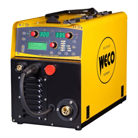
INTRODUCTION INTRODUCTION IMPORTANT! Micro Pulse 302 MFK is a compact and rugged three-phase, synergic This handbook must be consigned to the user prior to inverter power source for MIG/MAG, MMA and TIG Lift welding. installation and commissioning of the unit. -
Page 6: Installation
Cod.006.0001.1720 Micro Pulse 302 MFK 10/01/2018 v2.7 ENGLISH INSTALLATION DANGER! REAR PANEL Lifting and positioning Read the warnings highlighted by the following symbols in the “General prescriptions for use”. CONNECTIONS TO THE ELECTRICAL MAINS NETWORK The characteristics of the mains power supply to which the equipment shall be connected are given in the section entitled “Technical data”... -
Page 7: Preparing For Mma Welding
Cod.006.0001.1720 Micro Pulse 302 MFK 10/01/2018 v2.7 ENGLISH PREPARING FOR MMA WELDING DANGER! Electric shock hazard! 1. Set the welding power source ON/OFF switch to “O” (unit de- Read the warnings highlighted by the following symbols in the energized). “General prescriptions for use”. -
Page 8: Preparing For Tig Welding
Cod.006.0001.1720 Micro Pulse 302 MFK 10/01/2018 v2.7 ENGLISH PREPARING FOR TIG WELDING 10. Connect the earth clamp to the workpiece being processed. 11. Set the welding power source ON/OFF switch to “I” (unit 1. Set the welding power source ON/OFF switch to “O” (unit de- powered). -
Page 9: Preparing For Mig/Mag Welding
Cod.006.0001.1720 Micro Pulse 302 MFK 10/01/2018 v2.7 ENGLISH PREPARING FOR MIG/MAG WELDING 2.6.1 WIRE SPOOL POSITIONING 1. Open the unit side door to gain access to the spool compartment. 2. Unscrew the cap of the spool holder. 2.6.2 POSITIONING THE WIRE IN THE WIRE FEEDER 1. -
Page 10: Connections To Sockets
Cod.006.0001.1720 Micro Pulse 302 MFK 10/01/2018 v2.7 ENGLISH 2.6.3 CONNECTIONS TO SOCKETS 5. Feed the wire between the wire feeder rolls and insert it into the MIG/MAG TORCH connector plug. 1. Set the welding power source ON/OFF switch to “O” (unit de- 6. - Page 11 Cod.006.0001.1720 Micro Pulse 302 MFK 10/01/2018 v2.7 ENGLISH 11/60...
-
Page 12: Commissioning
Cod.006.0001.1720 Micro Pulse 302 MFK 10/01/2018 v2.7 ENGLISH COMMISSIONING USER INTERFACE CODE SYMBOL DESCRIPTION MIG/MAG mode: When this LED illuminates the following parameter can be set: WELDING THICKNESS MIG/MAG mode: When this LED illuminates the following parameter can be set:... -
Page 13: Unit Power-Up
Cod.006.0001.1720 Micro Pulse 302 MFK 10/01/2018 v2.7 ENGLISH CODE SYMBOL DESCRIPTION During illumination of the following LEDs: The display shows the value of the selected parameter. Welding: The display shows the effective amperes value during welding. HOLD function: The display shows the latest measured current value. -
Page 14: Reset (Load Factory Settings)
Cod.006.0001.1720 Micro Pulse 302 MFK 10/01/2018 v2.7 ENGLISH RESET (LOAD FACTORY SETTINGS) The reset procedure involves complete restoration of the default values, parameters and memory settings set in the factory. The reset procedure is useful in the following cases: - Too many changes made to the welding parameters so user finds it difficult to restore defaults. -
Page 15: Set-Up (Initial Set-Up Of The Welding Power Source)
Cod.006.0001.1720 Micro Pulse 302 MFK 10/01/2018 v2.7 ENGLISH SET-UP (INITIAL SET-UP OF THE WELDING POWER SOURCE) With locked status active it is not possible to access this function. § 3.6 LOCKING PROCEDURE SET UP when device is switched on Set the welding power source ON/OFF switch to “O” to switch the unit off. -
Page 16: Work Hours Counter
Cod.006.0001.1720 Micro Pulse 302 MFK 10/01/2018 v2.7 ENGLISH COOLING TYPE - The cooler is always running when the power source is switched on. This mode is preferable for heavy duty and automatic welding procedures. OFF= - The cooler is always disabled because an air-cooled torch is in use. -
Page 17: Locking Procedure
Cod.006.0001.1720 Micro Pulse 302 MFK 10/01/2018 v2.7 ENGLISH CONTROL TYPE OFF= No remote controller enabled. RC03= The unit is enabled to receive commands from a remote control equipped with 1 potentiometer. RC04= The unit is enabled to receive commands from a remote control equipped with 2 potentiometer. -
Page 18: Gas Flow Adjustment
Cod.006.0001.1720 Micro Pulse 302 MFK 10/01/2018 v2.7 ENGLISH Disabling If a lock status is selected, you can only edit parameters permitted by the currently active lock status. If you cannot recall the password the only way to exit locked status is to perform the welding power source RESET procedure. -
Page 19: Calibrating The Welding Circuit
Cod.006.0001.1720 Micro Pulse 302 MFK 10/01/2018 v2.7 ENGLISH Power-up with operation of the cooler set to "OFF" Operation of the cooler and the cooler alarm are disabled. Welding is performed without liquid cooling of the torch. Torch change-over with operation of the cooler set to "AUTO"... -
Page 20: 3.10 Alarms Management
Cod.006.0001.1720 Micro Pulse 302 MFK 10/01/2018 v2.7 ENGLISH 3.10 ALARMS MANAGEMENT This LED illuminates if an incorrect operating condition occurs. An alarm message appears on the following display: D3 Tab. 3 - Alarm messages MESSAGE MEANING EVENT CHECKS - Make sure that the power required by the... -
Page 21: Welding Settings
Cod.006.0001.1720 Micro Pulse 302 MFK 10/01/2018 v2.7 ENGLISH WELDING SETTINGS TORCH TRIGGER MODES 4.1.1 2T MIG/MAG WELDING 1. Bring the torch up to the workpiece. 2. Press (1T) and keep the torch trigger pressed. The wire advances at the approach speed until making contact with the work. -
Page 22: 4T B-L Mig/Mag Welding
Cod.006.0001.1720 Micro Pulse 302 MFK 10/01/2018 v2.7 ENGLISH 4.1.6 4T B-L MIG/MAG WELDING 1. Bring the torch up to the workpiece. 2. Press (1T) and release (2T) the torch trigger. The wire advances at the approach speed until making contact with the work. -
Page 23: Selection Of The Welding Mode And Torch Trigger Procedure
Cod.006.0001.1720 Micro Pulse 302 MFK 10/01/2018 v2.7 ENGLISH SELECTION OF THE WELDING MODE AND TORCH TRIGGER PROCEDURE Specific torch trigger procedures are available in accordance with the selecting welding mode. The availability of certain procedures depends on whether or not certain parameters or functions of the unit are enabled or set in the associated menus. -
Page 24: Welding Parameters
Cod.006.0001.1720 Micro Pulse 302 MFK 10/01/2018 v2.7 ENGLISH WELDING PARAMETERS WELDING CURRENT - Lower gas consumption. - Oxidation of electrode tip (more difficult arc strike). Output current value during welding. ARC CORRECTION IN VOLTS HOT-START This parameter corrects the synergic voltage value relative to the This parameter aids electrode melting at the time of arc striking. - Page 25 Cod.006.0001.1720 Micro Pulse 302 MFK 10/01/2018 v2.7 ENGLISH - More reliable starting. If you set a value other than SYN, this value is stored and fixed. ARC SET Consequences of a higher value: - Wire significantly retracted into the torch nozzle.
- Page 26 Cod.006.0001.1720 Micro Pulse 302 MFK 10/01/2018 v2.7 ENGLISH The setting is dependent on the specific needs of the operator. ARC2 2PULS Values from 0.5 s to 1.0 s are suitable for the vast majority of Arc2 voltage in double pulsed mode applications.
-
Page 27: Parameters Activation
Cod.006.0001.1720 Micro Pulse 302 MFK 10/01/2018 v2.7 ENGLISH PARAMETERS ACTIVATION The welding parameters are available in accordance with the selected welding mode and procedure. Certain parameters are available only after other parameters or functions of the unit have been enabled or set. -
Page 28: Characteristics Of The Menu Levels
Cod.006.0001.1720 Micro Pulse 302 MFK 10/01/2018 v2.7 ENGLISH CHARACTERISTICS OF THE MENU LEVELS 1ST LEVEL The menu shows the setting of the most important welding parameters (or synergic settings) relative to the selected welding process. SYN: This code indicates that parameters control is synergic. -
Page 29: 3Rd Level
Cod.006.0001.1720 Micro Pulse 302 MFK 10/01/2018 v2.7 ENGLISH 3RD LEVEL The menu contains the settings and values that are changed infrequently and are to be set up the first time the unit is powered up. The changed parameters remain saved until the next modification or reset of the unit. -
Page 30: Welding Settings
Cod.006.0001.1720 Micro Pulse 302 MFK 10/01/2018 v2.7 ENGLISH WELDING SETTINGS ELECTRODE WELDING (MMA) This button serves to select the following welding mode: 6.1.1 PARAMETERS SETTING Using the encoder, edit the value of the parameter. The value appears on the following display: D1 The value is saved automatically. -
Page 31: Mig/Mag Welding
Cod.006.0001.1720 Micro Pulse 302 MFK 10/01/2018 v2.7 ENGLISH MIG/MAG WELDING 6.3.1 WELDING CURVES SELECTION Use these buttons to select the following parameter: MAT Use these buttons to select the following parameter: Ø Use these buttons to select the following parameter: GAS... - Page 32 Cod.006.0001.1720 Micro Pulse 302 MFK 10/01/2018 v2.7 ENGLISH S H O R T / S P R A Y S Y N M A T S G 2 / S G 3 P R Ø : 1 . 2 ...
-
Page 33: Manual Mig/Mag Welding
Cod.006.0001.1720 Micro Pulse 302 MFK 10/01/2018 v2.7 ENGLISH MANUAL MIG/MAG WELDING Welding is of the Short/Spray type. Adjustment of the main welding parameters, wire feed rate and voltage is entirely at the discretion of the operator. The optimal work point must be identified for the required welding type. -
Page 34: Synergic Mig/Mag Welding
Cod.006.0001.1720 Micro Pulse 302 MFK 10/01/2018 v2.7 ENGLISH SYNERGIC MIG/MAG WELDING Set the welding data (material, wire diameter, gas type), shown on display D3 and just one welding parameter, chosen from among wire feed rate, Amperes, and workpiece Thickness, shown on display D1. -
Page 35: Parameters Setting: (1St Level)
Cod.006.0001.1720 Micro Pulse 302 MFK 10/01/2018 v2.7 ENGLISH 6.5.2 PARAMETERS SETTING: (1ST LEVEL) Press this button to scroll the list of settings to edit. The LED associated with the selected setting will illuminate. The value relative to the selected setting appears on the following displays: D1 Using the encoder, edit the value of the selected setting. -
Page 36: Synergic Mig/Mag Parameters Setting (2Nd Level)
Cod.006.0001.1720 Micro Pulse 302 MFK 10/01/2018 v2.7 ENGLISH 6.5.3 SYNERGIC MIG/MAG PARAMETERS SETTING (2ND LEVEL) Press the button to enter the 2nd level menu. Use these buttons to scroll through the list of parameters to edit. Using the encoder, edit the value of the selected parameter. -
Page 37: Pulsed Synergic Mig/Mag Welding
Cod.006.0001.1720 Micro Pulse 302 MFK 10/01/2018 v2.7 ENGLISH PULSED SYNERGIC MIG/MAG WELDING Set the welding data (material, wire diameter, gas type), shown on display D3 and just one welding parameter, chosen from among wire feed rate, Amperes, and workpiece Thickness, shown on display D1. -
Page 38: Pulsed Synergic Mig/Mag Parameters Setting (2Nd Level)
Cod.006.0001.1720 Micro Pulse 302 MFK 10/01/2018 v2.7 ENGLISH 6.6.3 PULSED SYNERGIC MIG/MAG PARAMETERS SETTING (2ND LEVEL) Press the button to enter the 2nd level menu. Use these buttons to scroll through the list of parameters to edit. Using the encoder, edit the value of the selected parameter. -
Page 39: Double Pulsed Synergic Mig/Mag Welding
Cod.006.0001.1720 Micro Pulse 302 MFK 10/01/2018 v2.7 ENGLISH DOUBLE PULSED SYNERGIC MIG/MAG WELDING Set the welding data (material, wire diameter, gas type), shown on display D3 and just one welding parameter, chosen from among wire feed rate, Amperes, and workpiece Thickness, shown on display D1. -
Page 40: Double Pulsed Synergic Mig/Mag Parameters Setting (2Nd Level)
Cod.006.0001.1720 Micro Pulse 302 MFK 10/01/2018 v2.7 ENGLISH 6.7.3 DOUBLE PULSED SYNERGIC MIG/MAG PARAMETERS SETTING (2ND LEVEL) Press the button to enter the 2nd level menu. Use these buttons to scroll through the list of parameters to edit. Using the encoder, edit the value of the selected parameter. -
Page 41: Jobs Management
Cod.006.0001.1720 Micro Pulse 302 MFK 10/01/2018 v2.7 ENGLISH JOBS MANAGEMENT Personalised welding settings, or JOBs, can be saved in memory locations and subsequently uploaded. Up to 99 jobs can be saved (j01-j99). The settings of the SETUP menu are not saved. -
Page 42: Deleting A Job
Cod.006.0001.1720 Micro Pulse 302 MFK 10/01/2018 v2.7 ENGLISH 6.8.3 DELETING A JOB Press the button. The job menu appears in the following displays: D3 Use these buttons to select the following parameter: OPT The selected parameter is shown by the following symbol: ... -
Page 43: Technical Data
Cod.006.0001.1720 Micro Pulse 302 MFK 10/01/2018 v2.7 ENGLISH TECHNICAL DATA Waste electrical and electronic equipment (WEEE) Electromagnetic compatibility (EMC) Directives applied Low voltage (LVD) Restriction of the use of certain hazardous substances (RoHS) Construction standards EN 60974-1; EN 60974-5; EN 60974-10 Class A... - Page 44 Cod.006.0001.1720 Micro Pulse 302 MFK 10/01/2018 v2.7 ENGLISH 40 % (40° C) 8.0 A 60 % (40° C) 8.2 A 100 % (40° C) 8.8 A 50 % (40° C) 6.2 A Maximum effective supply current 60 % (40° C) 6.4 A...
-
Page 45: Spare Parts
Cod.006.0001.1720 Micro Pulse 302 MFK 10/01/2018 v2.7 ENGLISH SPARE PARTS MICRO PULSE 302 MFK 45/60... - Page 46 Cod.006.0001.1720 Micro Pulse 302 MFK 10/01/2018 v2.7 ENGLISH N° CODE DESCRIPTION N° CODE DESCRIPTION 050.5121.0000 COMPLETE FRONT LOGIC PANEL 050.0003.0091 POWER BOARD 016.0011.0004 012.0003.0000 INTERNAL FRAMEWORKS 040.0007.1160 FUSE 011.0000.0881 COVER PANEL 021.0001.0259 COMPLETE FIXED SOCKET 050.0003.0044 SNUBBER BOARD 022.0002.0270 RS232 CABLE (COM1) 045.0006.0079...
-
Page 47: Wire Feeder Motor
Cod.006.0001.1720 Micro Pulse 302 MFK 10/01/2018 v2.7 ENGLISH WIRE FEEDER MOTOR 47/60... - Page 48 Cod.006.0001.1720 Micro Pulse 302 MFK 10/01/2018 v2.7 ENGLISH N° CODE DESCRIPTION 002.0000.0353 MOTOR COIL 002.0000.0308 SPACER RING 002.0000.0349 NUT M6 002.0000.0348 NUT M5 002.0000.0327 FEED PLATE 002.0000.0347 SCREW M4x18 002.0000.0350 SCREW M6x12 002.0000.0341 SHAFT (1) 002.0000.0343 MAIN GEAR DRIVE 002.0000.0340 SHAFT(2) 002.0000.0342...
-
Page 49: Wire Feeder Rolls
Cod.006.0001.1720 Micro Pulse 302 MFK 10/01/2018 v2.7 ENGLISH WIRE FEEDER ROLLS DOUBLE DRIVING ROLL (2 ROLL WITH GROOVE + 2 FLAT ROLL) Ø ROLL CODE Ø WIRE GROOVE TYPE ROLL 0.8/1.0 D=30x12/d=14 V 002.0000.0120 0.8-1.0 ROLL 1.0/1.2 D=30x12/d=14 V 002.0000.0121 1.0-1.2... - Page 50 Cod.006.0001.1720 Micro Pulse 302 MFK 10/01/2018 v2.7 ENGLISH DOUBLE DRIVING ROLL (4 ROLL WITH GROOVE) - RECOMMENDED CONFIGURATION Ø ROLL CODE Ø WIRE GROOVE TYPE D=30X12/d=14 V DOUBLE D. 002.0000.0170 0.8-1.0 D=30X12/d=14 VK DOUBLE D. 002.0000.0178 1.0-1.2 GEAR ADAPTOR FEED ROLL (BRONZE BUSHING) 002.0000.0369...
- Page 51 Cod.006.0001.1720 Micro Pulse 302 MFK 10/01/2018 v2.7 ENGLISH STANDARD FEED ROLLS VS TWIN FEED ROLLS Standard feed rolls Twin feed rolls Position of the wire centre in relation to the groove borders 51/60...
- Page 52 Cod.006.0001.1720 Micro Pulse 302 MFK 10/01/2018 v2.7 ENGLISH 52/60...
-
Page 53: Electrical Diagram
Cod.006.0001.1720 Micro Pulse 302 MFK 10/01/2018 v2.7 ENGLISH ELECTRICAL DIAGRAM 53/60... - Page 54 Cod.006.0001.1720 Micro Pulse 302 MFK 10/01/2018 v2.7 ENGLISH 54/60...
- Page 55 Cod.006.0001.1720 Micro Pulse 302 MFK 10/01/2018 v2.7 ENGLISH 55/60...
- Page 56 Cod.006.0001.1720 Micro Pulse 302 MFK 10/01/2018 v2.7 ENGLISH 56/60...
- Page 57 Cod.006.0001.1720 Micro Pulse 302 MFK 10/01/2018 v2.7 ENGLISH 57/60...
-
Page 58: Remote Controller
Cod.006.0001.1720 Micro Pulse 302 MFK 10/01/2018 v2.7 ENGLISH 9.1.1 RC03: ELECTRICAL DIAGRAM REMOTE CONTROLLER 10 kOhm-100 kOhm potentiometer Name Voltage Input/Output +5V-ISO 5 Vd.c. 9.1.2 RC04: ELECTRICAL DIAGRAM AN REM IN2 0-5 Va.c. AN REM IN1 0-5 Va.c. GND-ISO DIG REM IN1 0-5 Vd.c. -
Page 59: Rc05: Electrical Diagram
Cod.006.0001.1720 Micro Pulse 302 MFK 10/01/2018 v2.7 ENGLISH 9.1.3 RC05: ELECTRICAL DIAGRAM 9.1.4 RC06: ELECTRICAL DIAGRAM 59/60... - Page 60 Cod.006.0001.1720 Micro Pulse 302 MFK 10/01/2018 v2.7 ENGLISH 60/60...
Need help?
Do you have a question about the Micro Pulse 302 MFK and is the answer not in the manual?
Questions and answers