
Subscribe to Our Youtube Channel
Related Manuals for Weco Micro Mag 302 MFK


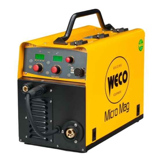
Summary of Contents for Weco Micro Mag 302 MFK
- Page 1 Cod.006.0001.1360 31/01/2018 v2.9 ENGLISH Micro Mag 302 MFK Instruction manual Antwerpsesteenweg 949 9041 Gent - Oostakker info@welda.be T +32 (0)9 355 74 26 www.welda.be F +32 (0)9 355 92 01...
- Page 2 Cod.006.0001.1360 31/01/2018 v2.9 Micro Mag 302 MFK ENGLISH 2/34 Antwerpsesteenweg 949 9041 Gent - Oostakker info@welda.be T +32 (0)9 355 74 26 www.welda.be F +32 (0)9 355 92 01...
-
Page 3: Table Of Contents
TECHNICAL DATA ..................................24 SPARE PARTS .................................... 26 WIRE FEED MOTOR ..................................28 WIRE FEEDER ROLLS ................................29 ELECTRICAL DIAGRAM ................................30 MICRO MAG 302 MFK ................................. 30 REMOTE CONTROLLER ................................32 8.2.1 RC03: ELECTRICAL DIAGRAM..................................32 8.2.2 RC04: ELECTRICAL DIAGRAM..................................32 8.2.3... -
Page 4: Introduction
INTRODUCTION INTRODUCTION IMPORTANT! Micro Mag 302 MFK is a compact and rugged three-phase, synergic This handbook must be consigned to the user prior to inverter power source for MIG/MAG, MMA and TIG Lift welding. installation and commissioning of the unit. -
Page 5: Installation
Cod.006.0001.1360 Micro Mag 302 MFK 31/01/2018 v2.9 ENGLISH INSTALLATION DANGER! REAR PANEL Lifting and positioning Read the warnings highlighted by the following symbols in the “General prescriptions for use”. CONNECTIONS TO THE ELECTRICAL MAINS NETWORK The characteristics of the mains power supply to which the equipment shall be connected are given in the section entitled “Technical data”... -
Page 6: Preparing For Mma Welding
Cod.006.0001.1360 31/01/2018 v2.9 Micro Mag 302 MFK ENGLISH PREPARING FOR MMA WELDING Preparing for MMA (polarity to basic electrode) 1. Set the welding power source ON/OFF switch to “O” (unit de- energized). 2. Plug the power cable plug into a mains socket outlet. -
Page 7: Preparing For Tig Welding
Cod.006.0001.1360 Micro Mag 302 MFK 31/01/2018 v2.9 ENGLISH PREPARING FOR TIG WELDING Preparing for TIG (polarity for tungsten electrode) 1. Set the welding power source ON/OFF switch to “O” (unit de- energized). 2. Plug the power cable plug into a mains socket outlet. -
Page 8: Preparing For Mig/Mag Welding
Cod.006.0001.1360 31/01/2018 v2.9 Micro Mag 302 MFK ENGLISH PREPARING FOR MIG/MAG WELDING 2.6.1 WIRE SPOOL POSITIONING 1. Open the unit side door to gain access to the spool compartment. 2. Unscrew the cap of the spool holder. 2.6.2 POSITIONING THE WIRE IN THE WIRE FEEDER 1. -
Page 9: Connections To Sockets
Cod.006.0001.1360 Micro Mag 302 MFK 31/01/2018 v2.9 ENGLISH 2.6.3 CONNECTIONS TO SOCKETS 5. Feed the wire between the wire feeder rolls and insert it into the MIG/MAG TORCH connector plug. 1. Set the welding power source ON/OFF switch to “O” (unit de- 6. - Page 10 Cod.006.0001.1360 31/01/2018 v2.9 Micro Mag 302 MFK ENGLISH Preparing for MIG/MAG 10/34 Antwerpsesteenweg 949 9041 Gent - Oostakker info@welda.be T +32 (0)9 355 74 26 www.welda.be F +32 (0)9 355 92 01...
-
Page 11: Commissioning
Cod.006.0001.1360 Micro Mag 302 MFK 31/01/2018 v2.9 ENGLISH COMMISSIONING USER INTERFACE CODE SYMBOL DESCRIPTION This LED illuminates to show an anomaly in the operating conditions. See § 3.7 ALARMS MANAGEMENT page 16. Illumination of this LED indicates the display of the average voltage and current value measured during the final moments of welding. - Page 12 Cod.006.0001.1360 31/01/2018 v2.9 Micro Mag 302 MFK ENGLISH CODE SYMBOL DESCRIPTION Parameters/functions setting Manual MIG/MAG mode: the display shows the programmed wire feed rate. Synergic MIG/MAG mode: the display shows the value of the selected main welding parameter. Welding MIG/MAG mode: The display shows the modification of the main welding parameter.
-
Page 13: Unit Power-Up
Cod.006.0001.1360 Micro Mag 302 MFK 31/01/2018 v2.9 ENGLISH CODE SYMBOL DESCRIPTION Manual MIG/MAG mode: the potentiometer sets the inductance value. POT1 Synergic MIG/MAG mode: the potentiometer sets the inductance value from the minimum to the maximum permissible value in accordance with the selected synergic curve. -
Page 14: Set-Up (Initial Set-Up Of The Welding Power Source)
Cod.006.0001.1360 31/01/2018 v2.9 Micro Mag 302 MFK ENGLISH SET-UP (INITIAL SET-UP OF THE WELDING POWER SOURCE) Set the welding power source ON/OFF switch to “O” to switch the unit off. SEL1 Use this selector to select one of the following welding modes: MIG/MAG Hold down the button. -
Page 15: Locking Procedure
Cod.006.0001.1360 Micro Mag 302 MFK 31/01/2018 v2.9 ENGLISH LOCKING PROCEDURE The locks are enabled only in MIG/MAG welding mode. The procedure inhibits unit adjustments, allowing the user to modify only certain settings depending on the selected lock status. The procedure is used to prevent accidental alteration of the unit settings and welding settings by the operator. -
Page 16: Alarms Management
Cod.006.0001.1360 31/01/2018 v2.9 Micro Mag 302 MFK ENGLISH ALARMS MANAGEMENT This LED illuminates if an incorrect operating condition occurs. An alarm message appears on the following display: D3 Tab. 4 - Alarm messages MESSAGE MEANING EVENT CHECKS - Make sure that the power required by All functions disabled. -
Page 17: Welding Settings
Cod.006.0001.1360 Micro Mag 302 MFK 31/01/2018 v2.9 ENGLISH WELDING SETTINGS TORCH TRIGGER MODES 2 STROKE LIFT-ARC TIG WELDING (2T) 1. Touch the workpiece with the torch electrode. 2. Press (1T) and keep the torch trigger pressed. 3. Slowly lift the torch to strike the arc. -
Page 18: Selection Of The Welding Mode And Torch Trigger Procedure
Cod.006.0001.1360 31/01/2018 v2.9 Micro Mag 302 MFK ENGLISH SELECTION OF THE WELDING MODE AND TORCH TRIGGER PROCEDURE Specific torch trigger procedures are available in accordance with the selecting welding mode. The availability of certain procedures depends on whether or not certain parameters or functions of the unit are enabled or set in the associated menus. -
Page 19: Welding Parameters
Cod.006.0001.1360 Micro Mag 302 MFK 31/01/2018 v2.9 ENGLISH WELDING PARAMETERS WELDING CURRENT CAUTION: an excessively long value will slow the welding procedure. Other than in the presence of special requirements the value should Output current value during welding. generally be kept at 0.0 s or anyway very low. -
Page 20: Welding Settings
Cod.006.0001.1360 31/01/2018 v2.9 Micro Mag 302 MFK ENGLISH WELDING SETTINGS ELECTRODE WELDING (MMA) SEL1 Select the following welding mode on the selector located in the spool compartment: MMA The message appears on the following displays: D2 5.1.1 PARAMETERS SETTING Using the encoder, edit the value of the parameter. -
Page 21: Mig/Mag Welding
Cod.006.0001.1360 Micro Mag 302 MFK 31/01/2018 v2.9 ENGLISH MIG/MAG WELDING SEL1 Select the following welding mode on the selector located in the spool compartment: MIG/MAG 5.3.1 PARAMETERS SETTING ARC CORRECTION Using the encoder, edit the value of the parameter. The value is saved automatically. -
Page 22: Parameters Setting: (2Nd Level)
Cod.006.0001.1360 31/01/2018 v2.9 Micro Mag 302 MFK ENGLISH 5.3.3 PARAMETERS SETTING: (2ND LEVEL) Hold down the button for 3 seconds to gain access to the 2nd level menu. The acronym relative to the setting to be edited appears on the following displays: D1 The value relative to the selected setting appears on the following displays: D2 Use the encoder to scroll the list of settings to edit. -
Page 23: Jobs Management
Cod.006.0001.1360 Micro Mag 302 MFK 31/01/2018 v2.9 ENGLISH JOBS MANAGEMENT Personalised welding settings, or JOBs, can be saved in memory locations and subsequently uploaded. Up to 50 JOBS can be saved (j01-j50). The settings of the SETUP menu are not saved. -
Page 24: Technical Data
Cod.006.0001.1360 31/01/2018 v2.9 Micro Mag 302 MFK ENGLISH TECHNICAL DATA Waste electrical and electronic equipment (WEEE) Electromagnetic compatibility (EMC) Directives applied Low voltage (LVD) Restriction of the use of certain hazardous substances (RoHS) Construction standards EN 60974-1; EN 60974-5; EN 60974-10 Class A... - Page 25 Cod.006.0001.1360 Micro Mag 302 MFK 31/01/2018 v2.9 ENGLISH 40 % (40° C) 8.0 A 60 % (40° C) 8.2 A 100 % (40° C) 8.8 A 50 % (40° C) 6.2 A Maximum effective supply current 60 % (40° C) 6.4 A...
-
Page 26: Spare Parts
Cod.006.0001.1360 31/01/2018 v2.9 Micro Mag 302 MFK ENGLISH SPARE PARTS 26/34 Antwerpsesteenweg 949 9041 Gent - Oostakker info@welda.be T +32 (0)9 355 74 26 www.welda.be F +32 (0)9 355 92 01... - Page 27 Cod.006.0001.1360 Micro Mag 302 MFK 31/01/2018 v2.9 ENGLISH N° CODE DESCRIPTION 050.5069.0000 COMPLETE FRONT PANEL 016.0011.0014 CAP D=19 016.0011.0004 FUSE HOLDER CAP 040.0007.1063 FUSE 022.0002.0177 REMOTE CONTROL CONNECTOR + CABLE 022.0002.0198 RED LED CABLE 022.0002.0055 POLARITY SELECTOR CABLE 011.0009.0208 BLIND METAL FRONT PLATE 021.0001.0259...
-
Page 28: Wire Feed Motor
Cod.006.0001.1360 31/01/2018 v2.9 Micro Mag 302 MFK ENGLISH WIRE FEED MOTOR 28/34 Antwerpsesteenweg 949 9041 Gent - Oostakker info@welda.be T +32 (0)9 355 74 26 www.welda.be F +32 (0)9 355 92 01... -
Page 29: Wire Feeder Rolls
Cod.006.0001.1360 Micro Mag 302 MFK 31/01/2018 v2.9 ENGLISH N° CODE DESCRIPTION 002.0000.0205 COMPLETE PRESSURE ARM 002.0000.0203 COMPLETE PRESSURE DEVICE 002.0000.0201 MOTOR COIL 002.0000.0259 INLET GUIDE WITH SOFT LINER 002.0000.0202 FEED PLATE 002.0000.0266 GUARD SAFETY KIT 002.0000.0212 INSULATION MOUNTING KIT 002.0000.0209 GEAR ADAPTOR FEED ROLL 002.0000.0210... -
Page 30: Electrical Diagram
Cod.006.0001.1360 31/01/2018 v2.9 Micro Mag 302 MFK ENGLISH ELECTRICAL DIAGRAM MICRO MAG 302 MFK 30/34 Antwerpsesteenweg 949 9041 Gent - Oostakker info@welda.be T +32 (0)9 355 74 26 www.welda.be F +32 (0)9 355 92 01... - Page 31 Cod.006.0001.1360 Micro Mag 302 MFK 31/01/2018 v2.9 ENGLISH 31/34 Antwerpsesteenweg 949 9041 Gent - Oostakker info@welda.be T +32 (0)9 355 74 26 www.welda.be F +32 (0)9 355 92 01...
-
Page 32: Remote Controller
Cod.006.0001.1360 31/01/2018 v2.9 Micro Mag 302 MFK ENGLISH 8.2.1 RC03: ELECTRICAL DIAGRAM REMOTE CONTROLLER Name Voltage Input/Output +5 V 5 Vd.c. AN2 (5 V) 0-5 Va.c. AN1 (5 V) 0-5 Va.c. 10 kOhm-100 kOhm potentiometer D1-IN 0-5 Vd.c. 8.2.2 RC04: ELECTRICAL DIAGRAM AN2 (10 V) 0-10 Va.c. -
Page 33: Rc05: Electrical Diagram
Cod.006.0001.1360 Micro Mag 302 MFK 31/01/2018 v2.9 ENGLISH 8.2.3 RC05: ELECTRICAL DIAGRAM 8.2.4 RC06: ELECTRICAL DIAGRAM 33/34 Antwerpsesteenweg 949 9041 Gent - Oostakker info@welda.be T +32 (0)9 355 74 26 www.welda.be F +32 (0)9 355 92 01... - Page 34 Cod.006.0001.1360 31/01/2018 v2.9 Micro Mag 302 MFK ENGLISH 34/34 Antwerpsesteenweg 949 9041 Gent - Oostakker info@welda.be T +32 (0)9 355 74 26 www.welda.be F +32 (0)9 355 92 01...
Need help?
Do you have a question about the Micro Mag 302 MFK and is the answer not in the manual?
Questions and answers