Table of Contents

Subscribe to Our Youtube Channel
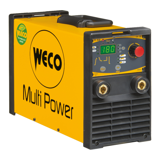
Summary of Contents for Weco Multi Power 184
- Page 1 Cod.006.0001.1380 17/01/2020 v2.6 ENGLISH WECO srl Via S. Antonio, 22 - BELVEDERE 36056 TEZZE SUL BRENTA (VICENZA) ITALY Tel.+39 0424 561943 – Fax +39 0424 561944 www.weco.it - E-mail info@weco.it Multi Power 184 Instruction manual...
- Page 2 Cod.006.0001.1380 17/01/2020 v2.6 Multi Power 184 ENGLISH 2/22...
-
Page 3: Table Of Contents
11.2.2 DC TIG PARAMETERS SETTING (2ND LEVEL) ......13 TORCH TRIGGER MODES ..........14 12.1 LIFT-ARC WELDING ............14 TECHNICAL DATA ............15 SPARE PARTS ..............16 ELECTRICAL DIAGRAM ..........18 15.1 MULTI POWER 184 ............18 15.2 REMOTE CONTROLLER CONNECTOR ......20 3/22... -
Page 4: Introduction
This symbol identifies a reference to a chapter of the manual. This symbol accompanies important information concerning the execution of the relevant operations. Multi Power 184 is an inverter DC TIG/MMA portable welding power 1: Positive pole welding socket. source. -
Page 5: Rear Panel
Cod.006.0001.1380 Multi Power 184 17/01/2020 v2.6 ENGLISH PREPARING FOR MMA WELDING REAR PANEL 1. Set the welding power source ON/OFF switch to “O” (unit de- energized). 2. Plug the power cable plug into a mains socket outlet. 3. Choose the electrode based on the type of material and thickness of the workpiece to be welded. -
Page 6: Preparing For Tig Welding
Cod.006.0001.1380 17/01/2020 v2.6 Multi Power 184 ENGLISH PREPARING FOR TIG WELDING 1. Set the welding power source ON/OFF switch to “O” (unit de- energized). 2. Plug the power cable plug into a mains socket outlet. Connect the gas hose of the TIG torch with gas valve to the pressure regulator of the gas cylinder. -
Page 7: User Interface
Cod.006.0001.1380 Multi Power 184 17/01/2020 v2.6 ENGLISH USER INTERFACE CODE SYMBOL DESCRIPTION This LED illuminates to show an anomaly in the operating conditions. See “ALARMS MANAGEMENT” (page 9). When this LED illuminates the last voltage and current average values measured during welding are shown on following displays: D1 The “HOLD”... -
Page 8: Unit Power-Up
Cod.006.0001.1380 17/01/2020 v2.6 Multi Power 184 ENGLISH CODE SYMBOL DESCRIPTION Parameters/functions setting: This button selects the parameter to be shown on the following display: D1 Possible choices: (A) Preset welding current (V) No-load voltage (EL) Preset type of electrode Welding: This button selects the parameter to be shown on the following display: D1... -
Page 9: Reset (Load Factory Settings)
Cod.006.0001.1380 Multi Power 184 17/01/2020 v2.6 ENGLISH RESET (LOAD FACTORY SETTINGS) The reset procedure involves complete restoration of the default values, parameters and memory settings set in the factory. All memory locations will be reset and hence all your personal welding settings will be lost! The reset procedure is useful in the following cases: ... -
Page 10: Derating
Cod.006.0001.1380 17/01/2020 v2.6 Multi Power 184 ENGLISH DERATING Derating is a machine function that cannot be selected by the user. Derating limits the maximum welding current if the supply voltage drops below 190Vac. For example, if the power source is set to weld with a current of 175A, that current will be the power source output until the supply voltage will range between 184Vac and 230Vac. -
Page 11: Welding Parameters
Cod.006.0001.1380 Multi Power 184 17/01/2020 v2.6 ENGLISH WELDING PARAMETERS Welding current. Remote control activation Output current value during welding. This parameter enables the unit to receive the current reference signal from a remote control. Hot-Start This parameter aids electrode melting at the time of arc striking. -
Page 12: Welding Settings
Cod.006.0001.1380 17/01/2020 v2.6 Multi Power 184 ENGLISH WELDING SETTINGS 11.1 ELECTRODE WELDING (MMA) - CELLULOSE WELDING (MMA CEL) Use this button to select one of the following welding modes: MMA MMA CEL 11.1.1 MMA – MMA CEL PARAMETERS SETTING (1ST LEVEL) Press the button to scroll the settings to edit. -
Page 13: Dc Tig Welding
Cod.006.0001.1380 Multi Power 184 17/01/2020 v2.6 ENGLISH Tab. 3 - Parameters of the 2nd level menu in MMA – MMA CEL mode PARAMETER MIN DEFAULT MAX bAS= basic rUt= rutile ELECTRODE TYPE Crn= chromium/nickel ALU= aluminium d.Ar. DYNAMIC ARC U.EL. -
Page 14: Torch Trigger Modes
Cod.006.0001.1380 17/01/2020 v2.6 Multi Power 184 ENGLISH This action will automatically close the menu. Exit with confirmation Press the button. This action will automatically close the menu. Tab. 5 - 2nd level menu parameters in DC TIG mode PARAMETER MIN DEFAULT... -
Page 15: Technical Data
Cod.006.0001.1380 Multi Power 184 17/01/2020 v2.6 ENGLISH TECHNICAL DATA Model Multi Power 184 EN 60974-1 Construction standards EN 60974-10 Class A 1 x 230V~ ± 15 % / 50-60 Hz Supply voltage 1 x 115V~ ± 15 % / 50-60 Hz... -
Page 16: Spare Parts
Cod.006.0001.1380 17/01/2020 v2.6 Multi Power 184 ENGLISH SPARE PARTS 16/22... - Page 17 Cod.006.0001.1380 Multi Power 184 17/01/2020 v2.6 ENGLISH N° CODE DESCRIPTION 011.0006.0031 HANDLE 011.0000.0121 UPPER COVER 050.0002.0165 LINE FILTER BOARD 050.0003.0169 COMPLETE POWER BOARD (with board .0166) 050.0002.0098 SNUBBER BOARD 032.0002.2403 ISOTOP DIODE 040.0003.1008 TERMAL SWITCH 050.0001.0154 PRIMARY RECTIFIER BOARD 046.0004.0009 TUNNEL PLASTIC INSULATION 010.0006.0044...
-
Page 18: Electrical Diagram
Cod.006.0001.1380 17/01/2020 v2.6 Multi Power 184 ENGLISH ELECTRICAL DIAGRAM 15.1 MULTI POWER 184 18/22... - Page 19 Cod.006.0001.1380 Multi Power 184 17/01/2020 v2.6 ENGLISH 19/22...
-
Page 20: Remote Controller Connector
Cod.006.0001.1380 17/01/2020 v2.6 Multi Power 184 ENGLISH 15.2 REMOTE CONTROLLER CONNECTOR cod. 021.0004.0602 Rc01: electrical diagram 2 kOhm - 10 kOhm potentiometer 20/22... - Page 21 Cod.006.0001.1380 Multi Power 184 17/01/2020 v2.6 ENGLISH 21/22...
- Page 22 Cod.006.0001.1380 17/01/2020 v2.6 Multi Power 184 ENGLISH 22/22...


Need help?
Do you have a question about the Multi Power 184 and is the answer not in the manual?
Questions and answers