Fanimation Brewmaster FP10 Series Owner's Manual
Belt-driven ceiling fans
Hide thumbs
Also See for Brewmaster FP10 Series:
- Specification sheet (2 pages) ,
- Owner's manual (16 pages) ,
- Owner's manual (16 pages)
Table of Contents
Advertisement
Available languages
Available languages
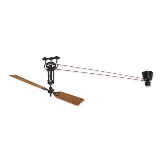
The Brewmaster
®
Belt-Driven Ceiling Fans
Long Neck FP20
Net Weight 15 lbs
(6.8 kg)
Motor Assembly
Net Weight 15 lbs
(6.8 kg)
Short Neck FP10
Net Weight 11 lbs
(5.0 kg)
Suitable for use with Solid State Speed Controls
WARNING: Support Directly From Building Structure
Model No. FP10 / 20 Fan Series
Model No. FP1280 Motor Series
OWNER'S MANUAL
READ AND SAVE THESE INSTRUCTIONS
Advertisement
Chapters
Table of Contents

Related Manuals for Fanimation Brewmaster FP10 Series


Summary of Contents for Fanimation Brewmaster FP10 Series
- Page 1 The Brewmaster ® Belt-Driven Ceiling Fans Long Neck FP20 Net Weight 15 lbs (6.8 kg) Motor Assembly Net Weight 15 lbs (6.8 kg) Short Neck FP10 Net Weight 11 lbs (5.0 kg) Suitable for use with Solid State Speed Controls WARNING: Support Directly From Building Structure Model No.
- Page 2 1. LIMITED LIFETIME MOTOR WARRANTY - If any part of your fan motor fails, due to a defect in materials or workmanship during the lifetime of the original purchaser, Fanimation will provide the replacement part free of charge, when the defective fan is returned to our national service center.
-
Page 3: Table Of Contents
6. All costs of removal and reinstallation of the fan are the sole responsibility of the owner of the fan and not the store that sold the fan 7. Fanimation reserves the right to modify or discontinue any product at any time and may substitute any part under this warranty. -
Page 4: Motor Assembly- Unpacking Instructions And Parts Identification
(Figure 1) Fanimation. Substitution of parts or accessories not designated for use with this product by Fanimation could • Pulley Head Assembly and hardware parts (Figure 2) result in personal injury or property damage. Contact your retail store for missing or damaged parts. -
Page 5: Pulley Assembly-Unpacking Instructions And Parts Identification
Pulley Assembly-Unpacking Instructions and Parts Identification FP10 (Short)/FP20 (Long) Pulley Assembly and Hardware Parts Identification FP20 FP10 Long Neck Short Neck Pulley Pulley Wood Blade Holders Assembly Assembly (for use with FP1022, FP1026, FP1030 blade sets) Traditional Blade Holders (for use with Palm, Bamboo, Wicker blade sets) Blade Holder to Hub Screws... -
Page 6: Electrical And Structural Requirements
Electrical and Structural Requirements Your new ceiling fan will require a grounded electrical Plywood (¾˝ thick min.) supply line of 120 volts AC, 60 Hz, 15 amp circuit. Backing Secured to Structural Member INSTALLATION NOTE Outlet Box Flush It is recommended that each fan and the motor have ¾˝ to Finished plywood backing secured to a structural member for Ceiling... -
Page 7: How To Set Your Switch Cap Remote Receiver
How to Set Your Switch Cap Remote Receiver This step is to be completed prior to hanging your motor. 1. Removing the Switch Housing: Remove the switch housing from the motor by unscrewing the three screws and unplugging the connector (Figures 1 & 2). 2. -
Page 8: How To Hang And Wire Your Ceiling Fan
& Flat Fanimation. Substitution of parts or accessories not Washer designated for use with this product by Fanimation could (4 places) result in personal injury or property damage. Contact your retail store for missing or damaged parts. - Page 9 How to Hang and Wire Your Ceiling Fan (continued) If you feel that you do not have enough electrical wiring knowledge or experience, have your fan installed by a licensed electrician. ▲WARNING To avoid possible electrical shock, be sure electricity is turned off at the main fuse box before wiring.
-
Page 10: Belt Splicing Instructions
Belt Splicing Instructions 1. Wrap the belting around the two pulleys that will be connected and overlap the belting as shown. Use the spring clamps provided to hold the belting in place temporarily. With the clamps remaining in the same place, grasp both ends of the belting and pull tight. -
Page 11: Mounting The Fan Blades
Mounting the Fan Blades CAUTION Side B Do not connect fan blades until the fan is completely installed. Hanging fan with blades connected may result in damage to the fan blades. Natural Palm Leaf, Woven Bamboo, Woven Wicker Blades Fan Blade 1. -
Page 12: Operating Instructions-Remote Control
Operating Instructions-Remote Control IMPORTANT: Using a full range dimmer switch (not included) to control fan speed will damage the fan. To reduce the risk of fire or electrical shock, do not use a full range dimmer switch to control the fan speed. (Figure 1) For illustrative purposes only-not intended to cover all types of controls... -
Page 13: How To Install Your Remote Control
How to Install Your Remote Control (Option #1) 1. Unthread two screws from the wall switch plate. (Figure 1) 2. Install the control bracket with two #6-32x 3/4” screws. And push the four plastic plug to cover the screw holes. (Included in the control packaging). -
Page 14: Maintenance
Maintenance Periodic cleaning of your new ceiling fan is the only CAUTION maintenance that is needed. When cleaning, use only a soft brush or lint free cloth to avoid scratching the fi nish. Do not use water when cleaning your ceiling fan. It could damage the motor or the blades and create the Abrasive and/or non-abrasive cleaning agents are not possibility of electrical shock. -
Page 15: Exploded-View Drawing & Parts List, Motor Assembly
The Brewmaster Motor FP1280** ® Exploded-View Drawing Parts List Ref. # Description Part # Brewmaster Motor Assembly FMA1280 Switch Cap Assembly PSW50 Control Receiver CR1280 Flat Washer Switch Cap Base Motor Pulley Set Screw 5/16-18 x 3/8 W/Locktite Motor Housing M/S, Washer Hd, -24 x 3½”, Black Motor... -
Page 16: Parts List, Pulley Assembly
Parts List Ref. # Description Part # Pulley Assembly FP10 /FP20 Pulley with set screw Short Frame (Short model) Long Frame (Long model) Cushion, Bearing, Black Bearing Shaft Blade Holder (2) (Wooden Blades only) P1212 Bag, BH to Hub Screws,10-32 x ½˝,Black (5) HDWFP10HB Bag, Lag Bolt, ¼˝... -
Page 17: Exploded-View Drawing, Pulley Assembly
The Brewmaster Pulley Assembly Pack ® FP10__ / FP20__ (Short) (Long) Exploded-View Drawing NOTE: The illustration shown is not to scale or its actual confi guration may vary. Figure 2... - Page 18 10983 Bennett Parkway Zionsville, IN 46077 Toll Free (888) 567-2055 FAX (866) 482-5215 Outside U.S. call (317) 733-4113 Visit Our Website www.fanimation.com Copyright 2015 Fanimation 2015/01 V.01...
- Page 19 The Brewmaster ® Ventiladores de techo con impulsión de correa Cuello Largo FP20 Peso neto 6.8kg (15lb) Conjunto del motor Peso neto 6.8kg (15lb) Cuello corto FP10 Peso neto 5.0kg (11lb) Apropiado para su uso con controles de velocidad de estado sólido ADVERTENCIA: Soporte directamente desde la estructura del edificio.
- Page 20 GARANTÍA LIMITADA DE POR VIDA DEL MOTOR - Si se produjera una falla en alguna de las partes del motor de su ventilador debido a un defecto en los materiales o en la fabricación durante el tiempo de vida del comprador original, Fanimation proporcionará la pieza de repuesto sin cargo una vez que el ventilador defectuoso sea devuelto a nuestro centro de servicios nacional.
- Page 21 En ningún caso se podrá devolver un ventilador sin previa autorización por parte de Fanimation. Las devoluciones autorizadas deberán ir acompañadas del recibo de venta y deberán enviarse a Fanimation, previo pago del flete. El ventilador que se devuelva deberá estar embalado en forma adecuada a fin de evitar daños durante el transporte. Fanimation no se hará responsable de los daños que resulten del embalaje incorrecto del producto.
-
Page 22: Unidad Del Motor-Instrucciones De Desembalaje E Identificación De Las Piezas
La sustitución de piezas o accesorios no integrado y las piezas del equipo (Figura 1) designados por Fanimation para usar con este producto • Unidad del cabezal de la polea y piezas del equipo podría ocasionar lesiones personales o daños en el ventilador. -
Page 23: Unidad De La Polea-Instrucciones De Desembalaje E Identificación De Las Piezas
Unidad de la polea-Instrucciones de desembalaje e identificación de las piezas Unidad de polea FP10 (Corta)/FP20 (Larga) e identificación de las piezas del equipo Unidad de la polea Unidad de la polea de cuello corto FP10 Soportes de pala de madera de cuello largo FP20 (para su uso con los sets de palas FP1022, FP1026, FP1030) -
Page 24: Requisitos Eléctricos Y Estructurales
Requisitos eléctricos y estructurales Su nuevo ventilador de techo requiere una línea de suministro eléctrico con conexión a tierra de 120 voltios de Contrachapado (¾˝ de grosor mín.) Parte posterior asegurada a la viga CA, 60 Hz, circuito de 15 amperios. de la estructura. -
Page 25: Cómo Configurar Del Receptor A Distancia
Cómo configurar del receptor a distancia Debe completar este paso antes de colgar su motor. 1. Extraiga la carcasa del interruptor: Extraiga la carcasa del interruptor del motor desatornillando los tres tornillos y desconectando el conector. (Figuras 1 & 2) 2. -
Page 26: Instalación Y Cableado Del Ventilador De Techo
Fanimation específicamente planas para el mismo. La sustitución de piezas o accesorios no designados por Fanimation para usar con este producto (4 ubicaciones) podría ocasionar lesiones personales o daños en el ventilador. Póngase en contacto con su tienda si faltan Tirafondos piezas o hay piezas dañadas. - Page 27 Instalación y cableado del ventilador de techo (Cont.) Si siente que no posee la experiencia o los conocimientos eléctricos necesarios, contrate a un electricista autorizado para instalar el ventilador. ▲ ADVERTENCIA VERDE o toma tierra Cable blanco de la fuente de Para evitar posibles descargas eléctricas, asegúrese Cable blanco del motor alimentación...
-
Page 28: Instrucciones Del Ensamblaje De La Correa
Instrucciones del ensamblaje de la correa 1. Enrolle la correa alrededor de las poleas para que quede conectada y esté montada en sí mismo como se muestra en la ilustración. Utilice las pinzas de muelles suministradas para mantener la correa en su sitio de forma temporal. Dejando las pinzas en el mismo sitio, agarre ambos extremos de la correa y tire con fuerza. -
Page 29: Montaje De Las Palas Del Ventilador
Montaje de las palas del ventilador PRECAUCIÓN Lado B No conecte las aspas hasta que el ventilador esté totalmente instalado. Instalar el ventilador con las aspas colocadas podría ocasionar daños en las mismas. Natural de hoja de palma, bambú tejido, tejido de mimbre Aspas Aspa 1. -
Page 30: Instrucciones De Funcionamiento-Control Remoto De Mano.30
Instrucciones de funcionamiento - Control remoto de mano ATERIA DE 3V, CR2032 2PCS 3. Funcionamiento y uso del Control remoto de mano: CONTROL REMOTO Instale dos piezas de la batería de 3 voltios (si no se va a utilizar por largos períodos de tiempo, retire la batería para evitar daños a control remoto de mano.) Guarde el Control Figura 3 remoto de mano lejos del exceso de calor o humedad. -
Page 31: Cómo Instalar Su Mando A Distancia
Cómo instalar su mando a distancia (Opción #1) 1. Retire los dos tornillos colocados en la plaza del interruptor de la pared. (Figura 1) 2. Instale el soporte de control con los dos tornillos #6-32x 3/4”. Empuje los cuatro tapones de plástico para cubrir los orificios de los tornillos. -
Page 32: Mantenimiento
Mantenimiento El único mantenimiento necesario para el ventilador de PRECAUCIÓN techo es una limpieza periódica. Al llevar a cabo la limpieza, use sólo un cepillo suave o un No utilice solventes para limpiar el ventilador de techo. Podrían dañar el motor o las aspas y ocasionar posibles paño sin pelusas, para evitar rayar el acabado. -
Page 33: Ilustración Del Despiece
The Brewmaster Motor Pack FP1280 ® Ilustración del despiece Lista de piezas N.º de ref. Descripción Pieza N.º Unidad del motor Brewmaster FMA1280 Unidad de la carcasa del interruptor PSW50 Receptor de control CR1280 Tuercas Arandelas planas Base de la carcasa del interruptor Polea del motor Tornillo de fijación de 5/16-18 x 3/8 con Loctite Carcasa del motor... -
Page 34: Lista De Piezas, Unidad De La Polea
Lista de piezas N.º de ref. Descripción Pieza N.º Unidad de la polea FP10 /FP20 Polea con tornillo de presión Marco corto (modelo corto) Marco largo (modelo largo) Funda, rodamiento, negro Rodamiento Centro Soporte de pala (2) (Solo de palas de madera) P1212 Bolsa, Tornillos de Soporte a Centro, 10-32 x ½˝, ˝... -
Page 35: Plano De Despiece, Unidad De La Polea
El pack de montaje de la polea Brewmaster® FP10__ (Corto) / FP20__ (Largo) Despiece NOTA: la ilustración que se muestra no está hecha a escala y su configuración real puede variar. Figura 2... - Page 36 10983 Bennett Parkway Zionsville, IN 46077 Llame Sin Cargo al (888) 567-2055 FAX (866) 482-5215 Desde fuera de los EE.UU. llame al (317) 733-4113 Visite nuestro sitio Web en www.fanimation.com Copyright 2015 Fanimation 2015/01 V.01...
Need help?
Do you have a question about the Brewmaster FP10 Series and is the answer not in the manual?
Questions and answers