Fanimation Palisade FP240 Series Owner's Manual
Standard & damp location models
Hide thumbs
Also See for Palisade FP240 Series:
- Specification sheet (2 pages) ,
- Owner's manual (32 pages)

Related Manuals for Fanimation Palisade FP240 Series


Summary of Contents for Fanimation Palisade FP240 Series
-
Page 1: Ceiling Fan
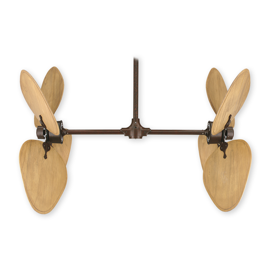
The Palisade ® Ceiling Fan Net Weight 21 kg (46 lbs) Standard & Damp Location Models Model No. FP240** OWNER’S MANUAL READ AND SAVE THESE INSTRUCTIONS Damp Location Model; Top of fan is marked, “Suitable For Use In Damp Locations”... -
Page 2: Table Of Contents
Fanimation. 7. Fanimation reserves the right to modify or discontinue any product at any time and may substitute any part under this warranty. 8. Under no circumstances may a fan be returned without prior authorization from Fanimation. The receipt of purchase must ac- company authorized returns and must be sent freight prepaid to Fanimation. -
Page 3: Tools Needed For Assembly
Fanimation. Substitution of parts or accessories not designated for use with this product by Fanimation could result in personal injury or property damage. Contact your retail store for missing or damaged parts. -
Page 4: Electrical And Structural Requirements
Electrical and Structural Requirements Your new ceiling fan will require a grounded electrical supply line of 120 volts AC, 60 Hz, 15 amp circuit. The outlet box must be securely anchored and capable of withstanding a load of at least 100 lbs. Figure 1 depicts different structural confi... -
Page 5: Fan Alignment And Hanger Bracket Installation
Assembling Crossbar To The Extension Pole (cont’d) ¼˝ x 2 ⁄ ˝ socket head bolts and locking nuts. Securely tighten both bolt and nut sets (Figure 2). 5. Slide Canopy over onto Extension Pole. 6. Route wires and safety cable though the Hanger Ball Adapter Assembly. -
Page 6: Final Fan Assembly
Fan Alignment And Hanger Bracket Installation (cont’d) 3. Hang the Crossbar / Pole Assembly (assembled earlier) into the the hanger bracket. Make sure the groove of the hanger ball is positioned on the tab of the hanger bracket. (Figure 2) 4. - Page 7 2. Using the styrofoam pad provided, position one motor at each end of the tube assembly. Securely attach plug from motor to socket on tube assembly. (Figure 2) 3. Push assembled plug inside of tube assembly and slide end of motor into tube assembly. ▲WARNING To avoid possible fire or shock, make sure that the electrical wires are completely inside the tube assembly...
-
Page 8: Wiring And Control Options
2. Optional fan & light slide wall control (C6). Please see instructions provided with control. NOTE: If you are using a Fanimation Light Fixture with your fan, see Ceiling Fan Light Kit Installation Instructions (packed with light kit) for wiring. -
Page 9: How To Wire Your Ceiling Fan - C3 Wall Control
How to Wire Your Ceiling Fan - C3 Wall Control If you feel that you do not have enough electrical wiring knowledge or experience, have your fan installed by a licensed electrician. NOTE: If fan or supply wires are different colors than indicated, have this unit installed by a qualifi... -
Page 10: Installing The Canopy Housing
You will fi nd the fan blade set packed in its own carton and the blade holders and hardware bag in the small hardware box in the fan box (FP240). The hardware bag for the blade holders consists of 16 screws and a Phillips head screwdriver. -
Page 11: Blade Attachment
INSTALLATION NOTE Attach the fan blades after hanging the fan body and wiring the fan to prevent blade breakage or damage. 1. Blade holders come packed in two different bundles, one blade holder set is marked with a red dot (4 pcs) and one blade holder set is marked with white dot (4 pcs). -
Page 12: Maintenance
Controlling Airfl ow Patterns (cont’d) Figure 3: Side A Reversing Switch Setting - with Red Dot Blade Arm Set - with White Dot Side B Reversing Switch Setting - with White Dot Blade Arm Set - with Red Dot Periodic cleaning of your new ceiling fan is the only maintenance that is needed. -
Page 13: Trouble Shooting
For your own safety turn off power at fuse box or circuit breaker before trouble shooting your fan. Trouble 1. Fuse or circuit breaker blown. 2. Loose power line connections to the fan, or loose switch wire connections in the switch housing. 1. -
Page 14: Parts List
Before discarding packaging materials, be certain all parts have been removed When ordering repair parts, always give the following information: Contact your retail store for repair parts. Parts List Model #FP240** Description ˝ Cap Head Bolt (2) ˝ Phillips Screws (17 pc) How To Order Parts •... -
Page 15: Exploded-View Drawing
The Palisade NOTE: The illustration shown is not to scale or its actual confi guration may vary, wires omitted for clarity. FP240** ® Exploded-View Figure 1 Side B Side A... - Page 16 10983 Bennett Parkway Zionsville, IN 46077 (888) 567-2055 FAX (866) 482-5215 Outside U.S. (317) 733-4113 Visit Our Website www.fanimation.com Copyright 2007 Fanimation 2007/05...
Need help?
Do you have a question about the Palisade FP240 Series and is the answer not in the manual?
Questions and answers